![]() Marine Electrical Products
Marine Electrical Products
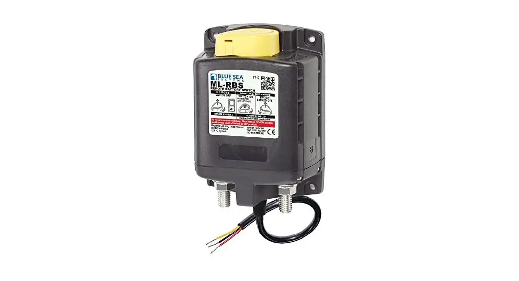
ML- RBS
Remote Battery Switches
PN 7713 / PN 7713B / PN 7713100B
PN 7717 / PN 7717B / PN 7717100B
- Magnetic Latch (ML) – draws very low current continuous and draws moderate current for a very short time when changing state
- Silver alloy contacts provide high reliability for switching live loads
- Manual override provides LOCK OFF capability for servicing and ON/OFF control with or without power
- LED output to remotely indicate switch state
- Tin-plated copper studs for maximum conductivity and corrosion resistance
- Label recesses for circuit identification
- PNs 7713 and 7717 include a Remote Control Switch PN 2155
Specifications | 12V | 24V | |
| Cranking Rating | See table below | See table below | |
| Intermittent Rating | See table below | See table below | |
| Continuous Rating | See table below | See table below | |
| ML-Coil Function | Auto releasing | Auto releasing | |
| Operating Current: Continuous Changing Stage (20 ms) Changing Stage (20 ms) | <13mA @ 25°C nominal voltage <7A @ 25°C nominal voltage | <13mA @ 25°C nominal voltage <4A @ 25°C nominal voltage | |
| Contact Circuit Voltage | 16V DC Max. | 32V DC Max. | |
| Live Current Switching | 300A @ 12V DC – 10,000 Cycles | 150A @ 24V DC – 10,000 Cycles | |
| Mechanical Endurance | 100,000 Cycles | 100,000 Cycles | |
| Control Circuit Voltage | 9–16V DC | 18–32V DC | |
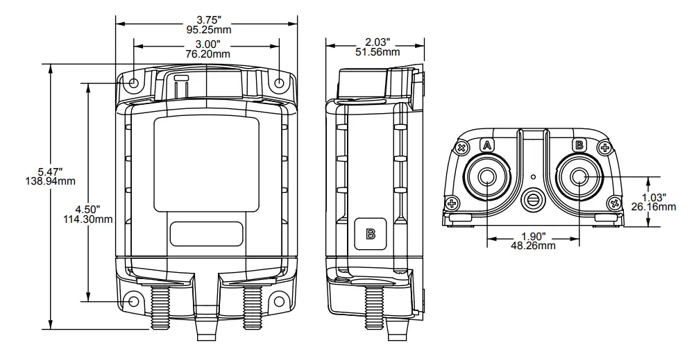
| Terminal Stud Size | 3/8″-16 | 3/8″-16 | |
| Maximum Terminal Stud Torque | 140 in-lb (15.8 N•m) | 140 in-lb (15.8 N•m) | |
| Ring Terminal Size | 3/8″ (M10) | 3/8″ (M10) | |
| Terminal Ring Diameter Clearance | 1.18″ (30 mm) | 1.18″ (30 mm) | |
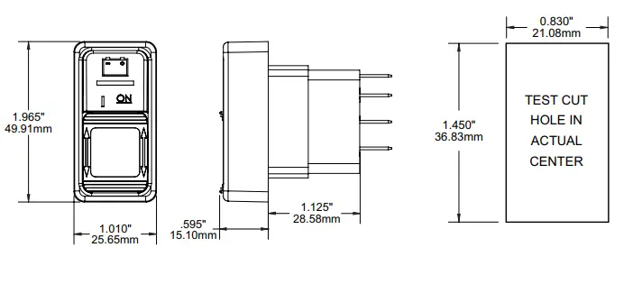
Remote Switch PN 2155 | |||
| Action | SPDT, ON-ON | ||
| Seals | Internal & External Gasket Panel Seal | ||
| Mounting Hole | 0.83″x 1.45″ (21.08 mm x 36.83 mm) | ||
| LED Rating | 100,000 hours half-life | ||
| Harness Connector: (select models) | Deutsch DTM Series DTM 06-6S | ||
| Mating Part Requirements | See LADD Industries www.laddinc.com | ||
| Receptacle Shell | DTM-04-6P | ||
| Wedgelock | WM-6P | ||
| Terminal Pins | 1060-20-0122 | ||
| Sealing Plugs | 0413-204-2005 | ||
| Hand Crimp Tooling | DTT-20-0 | ||
Regulatory Meets ISO 8846 and SAE J1171 external ignition protection requirements, CE marked, Rated IP66
Wire Size and Current Ratings
Wire Size | Cranking 30 sec. | Intermittent 5 min. | Continuous |
| 2/0 AWG (70 mm2) | 1,000A | 400A | 225A |
| 4/0 AWG (120 mm2) | 1,100A | 400A | 300A |
| 2x 4/0 AWG (2x 120 mm2) | 1,450A | 700A | 500A |
PN | Termination | Control Circuit | Remote Control Switch Included |
| 7713 | Tinned Wires | 12V DC | SPDT, ON-ON |
| 7713B | Tinned Wires | 12V DC | – |
| 7713100B | Deutsch Connector | 12V DC | – |
| 7717 | Tinned Wires | 24V DC | SPDT, ON-ON |
| 7717B | Tinned Wires | 24V DC | – |
| 7717100B | Deutsch Connector | 24V DC | – |
Overview of Application
The ML-Series Remote Battery Switch (ML-RBS) provides high-current carrying and switching under load.
The ML-RBS should be installed close to the battery to minimize voltage drop to the ML-RBS.
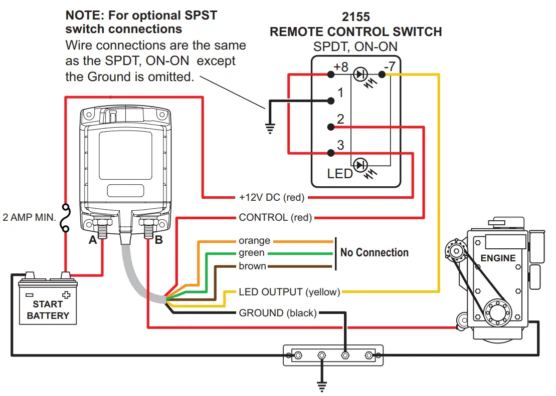
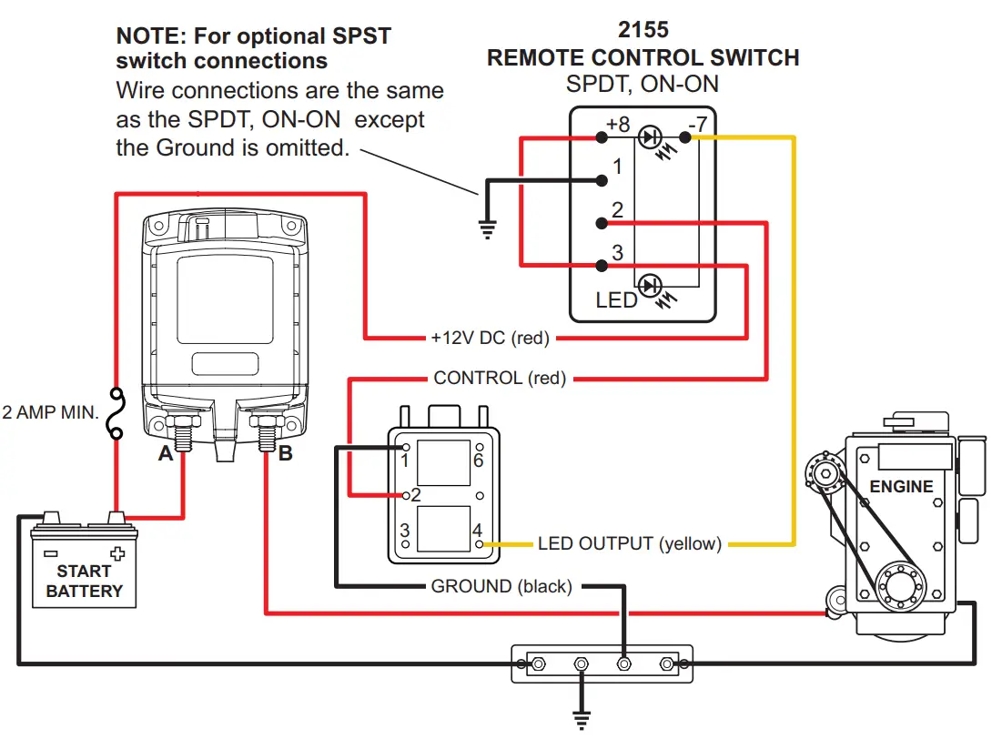
Install a single pole double throw (SPDT) or single pole single throw (SPST) control switch in a convenient location near other electrical controls or companionway to allow quick access in the event of an emergency (see Illustration on reverse).*
* Although an SPST switch may be used if desired, the use of an SPDT switch improves immunity to inadvertent switching if the switch terminals become damp.
Remote Operation
Remote Switch Operation | ML-RBS Relay State | Remote Control Switch LED | |
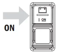 | To connect battery bank to load, or combine battery banks, press remote switch “ON”. |
| ON |
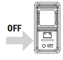 | To disconnect the battery bank from the load, or isolate the battery banks that are connected, press the remote 0switch “OFF”. |
| OFF |
 Remote Enabled ON (closed)
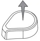 Remote Enabled OFF (open)
Manual Override Operation
ML-RBS Operation | ML-RBS Relay State | Remote Control Switch LED | |
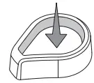
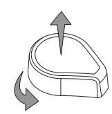 | To manually disconnect the battery bank from the load, or isolate battery banks that are connected, rotate the manual override knob to the right. |
| LED double blinking |
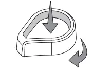 | To manually connect the battery bank to load, or combine battery banks that are connected, rotate the manual override knob to the left then push down until latched. |
| LED double blinking |
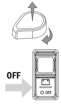 | To restore remote switching, manually set the RBS in the “Remote Enabled OFF (open)” position and push the remote switch “OFF”. |
| LED OFF |
![]() CAUTION
CAUTION![]()
![]() These instructions are intended to provide assistance with the installation of this product and are not a substitute for a more comprehensive understanding of electrical systems. We strongly recommend that a competent electrical professional perform the installation of this product.
These instructions are intended to provide assistance with the installation of this product and are not a substitute for a more comprehensive understanding of electrical systems. We strongly recommend that a competent electrical professional perform the installation of this product.![]() The illustrated wiring diagram represents a common installation and is not meant to be a guide for wiring a specific vessel. The wiring diagram shows a single battery bank installation.
The illustrated wiring diagram represents a common installation and is not meant to be a guide for wiring a specific vessel. The wiring diagram shows a single battery bank installation.![]() Disconnect all negative battery connections before beginning the installation.
Disconnect all negative battery connections before beginning the installation.![]() All unused control wires should be carefully insulated from each other and from accidental contact using heat shrink tubing or electrical tape. External contact or shorting between control wires can lead to malfunction.
All unused control wires should be carefully insulated from each other and from accidental contact using heat shrink tubing or electrical tape. External contact or shorting between control wires can lead to malfunction.
Installation Instructions
Mounting
Install as close as possible to the battery bank. To avoid corrosion to connecting wires and terminals, mount in a dry and protected location. Avoid mounting directly above vented lead-acid batteries so that the Remote Battery Switch is not exposed to corrosive gasses expelled from the batteries.
High Current Primary Circuit Connections (stud terminals A and B)
For help selecting the appropriate wire size and circuit protection rating, go to www.bluesea.com and click the Circuit Wizard quick link.
NOTE: Stud terminals A and B are interchangeable. A battery connection is required on one terminal for device operation
To connect high current circuit wires:
- Connect the battery bank to one of the stud terminals marked A or B.
- Connect the load to the other stud terminal marked B or A.
- Torque the high current terminal stud nuts to 140 in-lbs (15.5 N•m) maximum.
NOTE: If switching an inverter, windlass, bow thruster, etc., the circuit wires must have circuit protection to comply with ABYC guidelines. Wires used for engine starting do not require circuit protection.
Control Circuit Connections (wires contained in the wire harness)
NOTE: The Remote Battery Switch is designed to be controlled by an SPDT or SPST switch.
Use a minimum of 16 AWG wires for the Control Circuits. For help selecting the appropriate wire size for the load cables, go to www.bluesea.com and click the Circuit Wizard quick link.
To connect the SPDT Remote Control Switch 2155:
- Connect pin 3 and pin 8 to +12V or +24V Power available when Remote Battery Switch is OFF. (fused)
- Connect the red control wire to switch pin 2.
- Connect pin 7 to the yellow wire.
- Connect pin 1 to ground or negative.
Guarantee
Blue Sea Systems stands behind its products for as long as you own them.
Find detailed information at www.bluesea.com/about.
For customer service, call 800-222-7617.
Installation Instructions
 | Tinned Wire Termination |
Deutsch DTM Connector Termination | |
![]() Blue Sea Systems, Inc.
Blue Sea Systems, Inc.
4600 Ryzex Way Bellingham, WA 98226 USA
Phone 360.738.8230
www.bluesea.com


