Yard Guard CHAIN LINK FENCE
INSTALLATION INSTRUCTIONS
IMPORTANT Before You Start Digging…
- Check with local utility companies for cables, underground lines, etc.
- Check local codes regarding height, locations, etc. A permit may be necessary.
- Consult plat of survey or professional surveyor to ensure that your fence footings are located within your property lines.

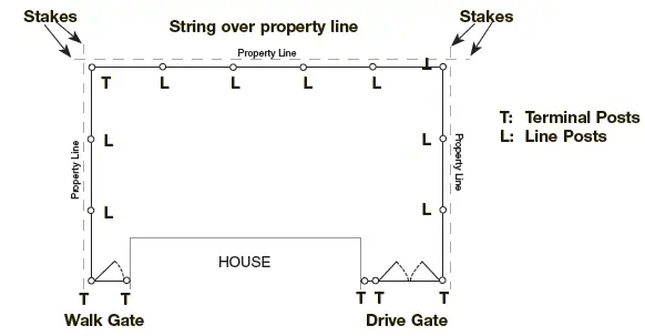
Locate Terminal Posts and Install (Corner, End and Gate Posts)
Determine the boundary lines of the property, insert stakes and stretch string around all stakes. Mark locations for all terminal posts (corner, end and gate) and make sure they are 4” inside property boundaries. Mark the location for each gate post with a stake. Gates come in standard opening widths of: Single Walk – 36”, 39”, 42” and 48”; Double Drive – 10’ and 12’. (i.e. if gate opening is 42”, gate post spacing should be exactly 42”, measured between inside post surfaces. If the opening is 48”, spacing should be exactly 48”. See Step 6). Dig all terminal post holes (refer to the diagram below for width and depth).
Mark the ground line on all posts for the correct height of fence. The height of the terminal posts, above ground, will equal the height of the chain link fabric plus 2”. The height of the line posts will equal the height of the fabric less 2”. Set terminal posts in fast-setting concrete in the center of hole keeping ground line at ground level. Use a level to check the plumb. Crown all post footings so water drains away from posts.
(NOTE: Use approximately one 50 lb. bag of fast-setting concrete for each line post hole, and two 50 lb. bags of fast-setting concrete for each terminal post.) 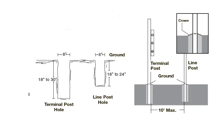
Locate Line Posts and Install
After the concrete has hardened, stretch a string (positioned on the outside post face) between terminal posts. The string should be 4” below the top of the post (see diagram below). Measure the distance between the terminal posts and refer to the Terminal/Line Post Spacing Chart on the reverse side for positioning of line posts. With stakes, mark the locations of all line posts and align with the centers of the terminal posts.
Dig all holes for line posts (refer to the diagram above for width and depth) and set posts in concrete.
After the concrete has hardened enough for posts to remain plumb, adjust all line posts to be even height with the string by gently moving posts up or down in the footings. (Use a carpenter’s level for accuracy). The outside faces of the line posts should be 1/4” inside the string line. 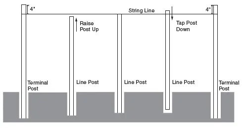
Install Fittings to Terminal Posts
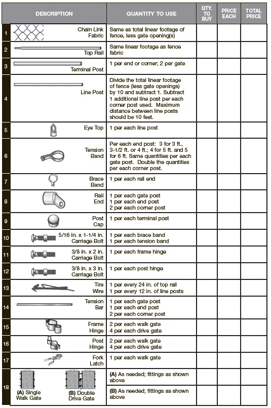
Review the Material Check List on the reverse side for descriptions and the number of fittings required.
After concrete footings have hardened, slip the tension bands over terminal posts making sure they are evenly spaced. The long, flat surface should face the outside of the fence. Carefully add brace bands making sure not to bend or distort. Bolt heads should be on the outside of the fence and threaded ends inside. Fit all post caps.
Install Top Rails
Place an eye top fitting on the end of each line post. Flat side should be toward the outside of the fence. Insert one length of top rail pipe through an eye top nearest a terminal post. Insert a
rail end on the top rail and attach to the terminal post with a brace band. Fasten with a 5/16” x 1-1/4” carriage bolt. Continue to join lengths of top rail by forcing swedged (or crimped) ends of top rail together through eye tops. (If joining non-swedged top rail sections, sleeves can be used as pictured below). When next terminal post is reached, measure and cut the top rail to fit tightly between the last length of top rail and the rail end fastened to the brace band on the terminal post. Fasten with a carriage bolt.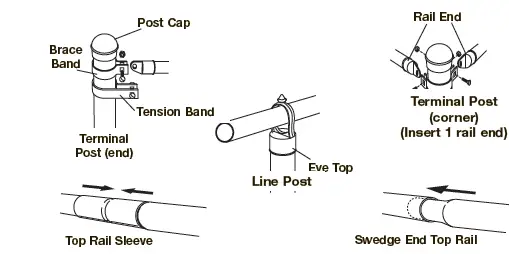
Affix and Stretch Chain Link Fabric
Beginning at a terminal post, lay the chain link fabric on the ground and unroll to next terminal post. Unroll enough fabric to cover the opening between the terminal posts. (See figure below for adding and removing fabric). Insert a tension bar through the end of the fabric and attach to tension bands that were previously placed on the terminal posts. Fasten (not too tightly) with 5/16” x 1-1/4” carriage bolts – heads on the outside of the fence and threaded ends inside.
Stand the entire fence section upright, leaning against the framework. Loosely attach the fabric to top rail with tie wires to hold in place. 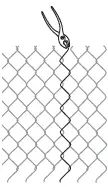
REMOVING FABRIC
With pliers, open the top and bottom ends of wire where you wish to terminate or remove the fabric. Unwind the strand and twist through the links until the wire comes out of the fabric, in a corkscrew manner.
ADDING OR SPLICING FABRIC
From the end of the fabric, remove a strand of wire. Join the two sections together and wind the removed wire down through the ends, in a corkscrew manner. Note: a second strand of wire may have to be removed in order to mesh properly.
From the terminal post, which already has fabric attached, stretch the fabric to the opposite terminal post (see diagram at right). Insert a tension bar 4 feet inside the open end of the fabric. Fasten one end of the fence stretcher to the tension bar or stretcher bar and the other end to the terminal post. Stretch the fabric until there is a slight tension when squeezed by hand. Either add or remove fabric for exact length. Insert a tension bar at end and connect to the tension bands on the terminal post. Remove the fence stretcher and secure the fabric to top rail with tie wires. Spacing should be 24” apart on top rail and 12” apart on online posts. Securely tighten nuts on all brace and tension bands.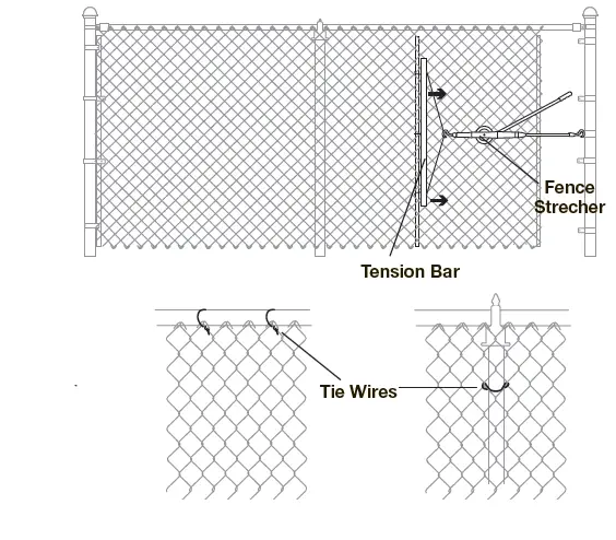
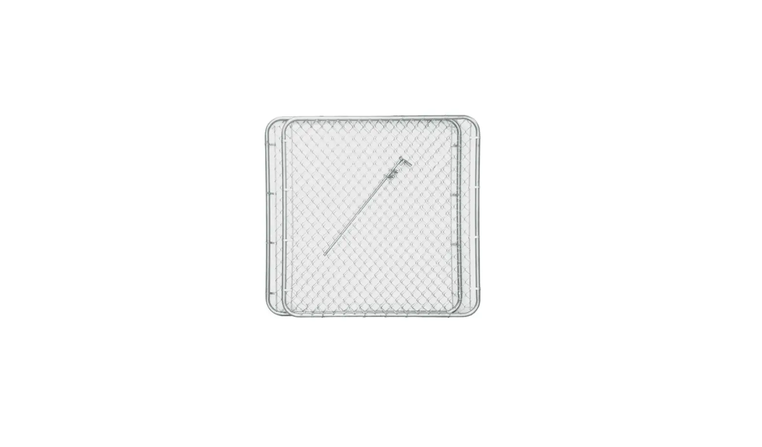
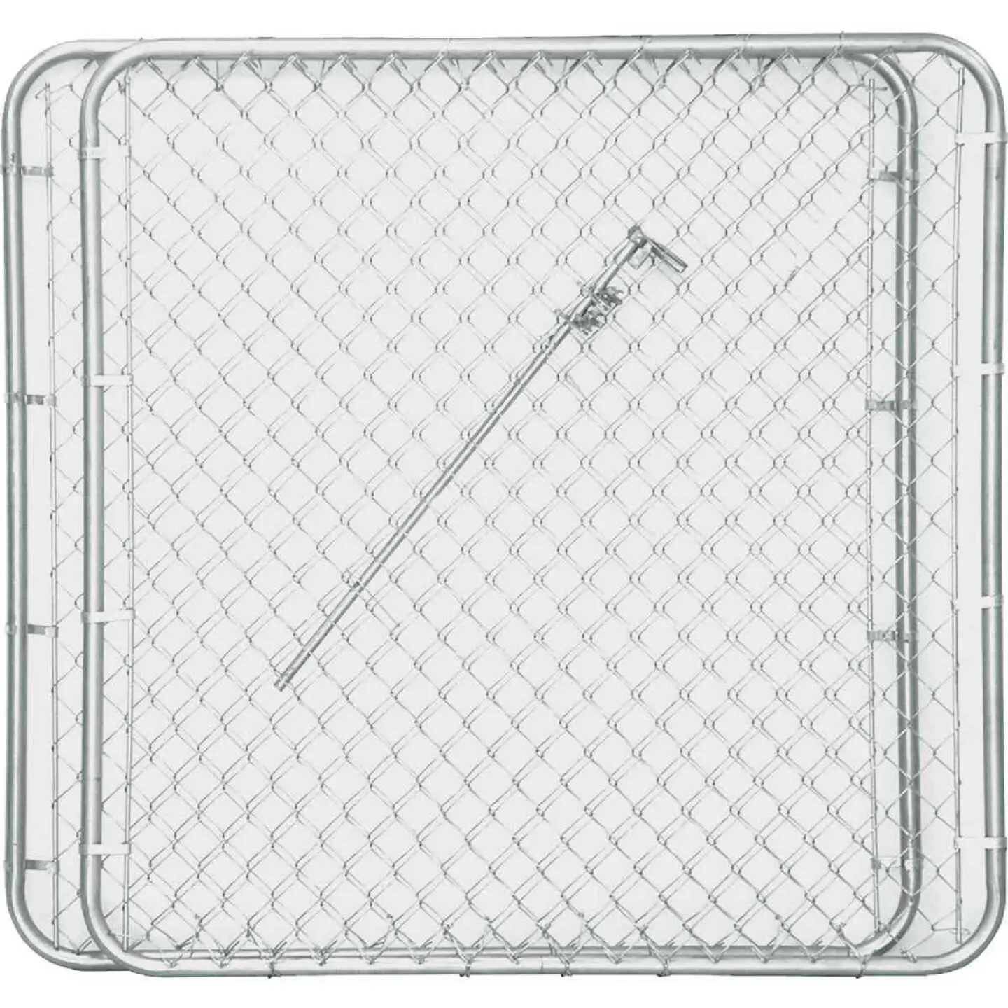
Hang Gates
Attach frame hinges to gate frame. Install post hinges to gate post. Install top post hinge with pinpointing down and the bottom post hinge with pin pointing up. This will prevent the gate from being lifted off the hinges. Place gate in position by aligning the top of the gate with the top of the fence and adjust the hinges to allow for a full swing. Install gate latch at a desired height that’s suitable to your usage and fasten all bolts.
Follow the same directions to install Drive Gates.
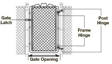
NOTE: Clearance for hinges and latches (4” for walk gates and 6” for drive gates) is included in the stated gate opening width.
PLANNING AND PURCHASING
Plan
Make a drawing of your fence in the space below: 
Use chart below to determine exact number of terminal and line posts you will need based on your final layout measurements. 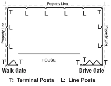
Measure
| TERMINAL SET LINE | TERMINAL | SET LINE | TERMINAL | SET LINE | ||||
| POST POSTS | POST | POSTS | POST | POSTS | ||||
| SPACING APART | SPACING | APART | SPACING | APART | ||||
| 30 ft. | 10 ft. | 54 ft. | 9 ft. | 78 ft. | 9 ft. 9 in. | |||
| 31 ft. | 7 ft. 9 in. | 55 ft. | 9 ft. 2 in. | 79 ft. | 9 ft. 10 in. | |||
| 32 ft. | 8 ft. | 56 ft. | 9 ft. 4 in. | 80 ft. | 10 ft. | |||
| 33 ft. | 8 ft. 3 in. | 57 ft. | 9 ft. 6 in. | 81 ft. | 9 ft. | |||
| 34 ft. | 8 ft. 6 in. | 58 ft. | 9 ft. 8 in. | 82 ft. | 9 ft. 1 in. | |||
| 35 ft. | 8 ft. 9 in. | 59 ft. | 9 ft.10 in. | 83 ft. | 9 ft. 3 in. | |||
| 36 ft. | 9 ft. | 60 ft. | 10 ft. | 84 ft. | 9 ft. 4 in. | |||
| 37 ft. | 9 ft. 3 in. | 61 ft. | 8 ft. 8 in. | 85 ft. | 9 ft. 6 in. | |||
| 38 ft. | 9 ft. 6 in. | 62 ft. | 8 ft.10 in. | 86 ft. | 9 ft. 7 in. | |||
| 39 ft. | 9 ft. 9 in. | 63 ft. | 9 ft. | 87 ft. | 9 ft. 8 in. | |||
| 40 ft. | 10 ft. | 64 ft. | 9 ft. 1 in. | 88 ft. | 9 ft. 9 in. | |||
| 41 ft. | 8 ft. 2 in. | 65 ft. | 9 ft. 3 in. | 89 ft. | 9 ft. 10 in. | |||
| 42 ft. | 8 ft. 5 in. | 66 ft. | 9 ft. 5 in. | 90 ft. | 10 ft. | |||
| 43 ft. | 8 ft. 6 in. | 67 ft. | 9 ft. 7 in. | 91 ft. | 9 ft. 1 in. | |||
| 44 ft. | 8 ft. 9 in. | 68 ft. | 9 ft. 8 in. | 92 ft. | 9 ft. 2 in. | |||
| 45 ft. | 9 ft. | 69 ft. | 9 ft.10 in. | 93 ft. | 9 ft. 3 in. | |||
| 46 ft. | 9 ft. 2 in. | 70 ft. | 10 ft. | 94 ft. | 9 ft. 5 in. | |||
| 47 ft. | 9 ft.5 in. | 71 ft. | 8 ft. 9 in. | 95 ft. | 9 ft. 6 in. | |||
| 48 ft. | 9 ft. 7 in. | 72 ft. | 9 ft. | 96 ft. | 9 ft. 7 in. | |||
| 49 ft. | 9 ft. 9 in. | 73 ft. | 9 ft. 2 in. | 97 ft. | 9 ft. 8 in. | |||
| 50 ft. | 10 ft. | 74 ft. | 9 ft. 3 in. | 98 ft. | 9 ft. 9 in. | |||
| 51 ft. | 8 ft. 6 in. | 75 ft. | 9 ft. 4 in. | 99 ft. | 9 ft. 10 in. | |||
| 52 ft. | 8 ft. 8 in. | 76 ft. | 9 ft. 6 in. | 100 ft. | 10 ft. | |||
| 53 ft. | 8 ft.10 in. | 77 ft. | 9 ft. 7 in. | |||||
Components Needed
| QTY | DESCRIPTION | QTY | DESCRIPTION | QTY | DESCRIPTION |
| 1 rl. | 4 ft. x 50 ft. Chain Link Fabric | 1 rl. | 5 ft. x 50 ft. Chain Link Fabric | 1 rl. | 6 ft. x 50 ft. Chain Link Fabric |
| 5 ea. | 1-3/8 in. x 10 ft. 6 in. Top Rails | 5 ea. | 1-3/8 in. x 10 ft. 6 in. Top Rails | 5 ea. | 1-3/8 in. x 10 ft. 6 in. Top Rails |
| 2 ea. | 2-3/8 in. x 5 ft.- 6 in. or 6 ft. Terminal Posts | 2 ea. | 2-3/8 in. x 7 ft. Terminal Posts | 2 ea. | 2-3/8 in. x 8 ft. Terminal Posts |
| 4 ea. | 1-5/8 in. x 5 ft. 6 in. or 6 ft. Line Posts | 4 ea. | 1-5/8 in. x 7 ft. Line Posts | 4 ea. | 1-5/8 in. x 8 ft. Line Posts |
| 4 ea. | 1-5/8 in. Eye Tops for Line Posts | 4 ea. | 1-5/8 in. Eye Tops for Line Posts | 4 ea. | 1-5/8 in. Eye Tops for Line Posts |
| 6 ea. | 2-3/8 in. Tension Bands | 8 ea. | 2-3/8 in. Tension Bands | 10 ea. | 2-3/8 in. Tension Bands |
| 2 ea. | 2-3/8 in. Brace Bands | 2 ea. | 2-3/8 in. Brace Bands | 2 ea. | 2-3/8 in. Brace Bands |
| 2 ea. | 1-3/8 in. Rail Ends | 2 ea. | 1-3/8 in. Rail Ends | 2 ea. | 1-3/8 in. Rail Ends |
| 2 ea. | 2-3/8 in. Post Caps For Terminal Posts | 2 ea. | 2-3/8 in. Post Caps For Terminal Posts | 2 ea. | 2-3/8 in. Post Caps For Terminal Posts |
| 1 bx. | 5/16 in. x 1-1/4 in. Carriage Bolts | 1 bx. | 5/16 in. x 1-1/4 in. Carriage Bolts | 2 bxs. | 5/16 in. x 1-1/4 in. Carriage Bolts |
| 2 pks. | 6-1/2 in. Aluminum Tie Wires | 2 pks. | 6-1/2 in. Aluminum Tie Wires | 2 pks. | 6-1/2 in. Aluminum Tie Wires |
| 2 ea. | 4 ft. Tension Bars | 2 ea. | 5 ft. Tension Bars | 2 ea. | 6 ft. Tension Bars |
| 1 rl. | 170 ft. Tension Wire Coil | 1 rl. | 170 ft. Tension Wire Coil | 1 rl. | 170 ft. Tension Wire Coil |
| 8 bgs. | Fast set Concrete | 8 bgs. | Fast set Concrete | 8 bgs. | Fast set Concrete |
| 1 pair | Gloves | 1 pair | Gloves | 1 pair | Gloves |
Choose Hardware & Accessories
Before You Start Your Project, Remember…
String, Stakes, Tape Measure, Post Hole Digger, Hoe, Shovel, Wrench, Pliers, Hacksaw, Carpenter’s Level, Fence Stretcher, Wheel Barrow, Stretcher Bar, Gloves
Learn more at
homedepot.com
Download PDF: Yard Guard CHAIN LINK FENCE User Manual


