RISCO EL-5829 2-Way Wireless LCD Keypad
Description
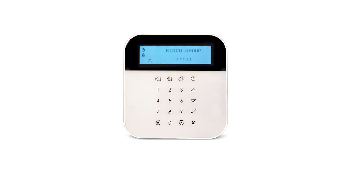
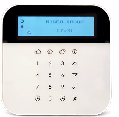
The EL-5829 is a 2-Way wireless keypad with LCD display used to remotely program and operate the iConnect 2-Way systems. The keypad’s functionality is identical to the keys on the iConnect 2-Way front panel.
Note: Programming mode can be established either from a keypad or from the main panel, but not simultaneously.
What’s in the Box
- 2-Way LCD wireless keypad
- 4 x CR123 Lithium batteries
- 5 wooden screws 3.5 x 25 mm
- Installation Instructions
Installation
Registration
The EL-5829 keypad must identify itself to the system receiver. This is done by registering the keypad to the iConnect 2-Way, as follows.
- Set the system to Registration mode.
- Go to the main menu and select [9]>[1]>[3] (Programming > Devices > Keypads).
- Select a keypad (1 – 4).
- Release the mounting bracket.
- Open the battery compartment and insert the batteries. Pay attention to the correct polarity.
- As soon as ‘Save?’ appears on the Control System’s LCD screen, press ‘√’.
Deleting a Keypad
To delete a wireless keypad from the system:
- Set the system to Delete mode.
- Go to the main menu and select [9]>[1]>[3] (Programming > Devices > Keypads).
- Select a keypad (1 – 4).
- Select the Delete menu.
- Press >
- Take out the keypad batteries.
- Insert the batteries.
- Within a 30-second time period, press and three seconds; the keypad will display the software version and ‘Not Registered’.
Wall Mounting
After the keypad has been registered to the system mount the keypad on the wall using the supplied mounting bracket.
Notes:
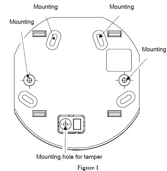
- Before mounting the keypad test the keypad communication with the system. To do so, try to arm the system using one of the arming buttons on the wireless keypad (see Figure 1).
- Minimum mounting distance between the wireless keypad and the panel is 1.5m.
To mount the keypad
- Release the mounting bracket.
- Attach the mounting bracket to the wall using the supplied screws (see figure 1).

- Attach the wireless keypad to the mounting bracket by sliding the keypad down onto the bracket‘s four hooks (see figure 2).

- Attach the housing screw at the bottom of the front cover (see figure 3).


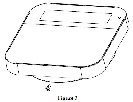
Note: To use the back tamper, the back-tamper screw must be installed.
Main User Operations
Control Keys
| Key | Operation |
| In Normal Operation mode: Used for Away (Full setting). | |
| In Normal Operation mode: Used for Stay arming (Part Setting). | |
| In Normal Operation mode: used to enter the menus with code. Long press: activates quick registration Used also to terminate commands and confirm data to be stored. | |
| In Normal Operation mode: Used for Perimeter arming. | |
| Provides the system status. | |
| Used to scroll up a list or to move the cursor to the left; | |
| Used to scroll down a list or to move the cursor to the right. To view system trouble list | |
| In User Functions menu: used to move back one step in the menu. Long press: activates quick delete mode |
Emergency Keys
| Key | Operation |
| + | Pressing both keys simultaneously for at least two seconds activates a Fire alarm |
| + | Pressing both keys simultaneously for at least two seconds activates an Emergency alarm |
| + | Pressing both keys simultaneously for at least two seconds activates a Police (Panic) alarm. Used for tele-control. In User Functions menu, used to change data: · To enter space, press left key · To delete data, press right key Long press of right key to activate Battery Replace mode |
The following operations will send emergency notifications to the alarm monitoring station.
Function Keys
| Key | Operation |
| Numerical keys that are used to input numeric codes (arming, disarming or used to activate specific functions). |
Visual Indicators
| Icon | Indication | Operation |
| Power | On | System is operating properly from AC power and backup battery is in good condition |
| Slow flash | Control Panel/Keypad low battery | |
| Rapid flash | Control Panel AC loss | |
| Trouble / Tamper | On | System trouble |
| Off | System is operating normally | |
| Rapid flash | Zone/keypad/external module has been tampered | |
| Ready | On | System is ready to be Set |
| Off | System is not ready to be Set/Arm | |
| Set / Alarm | On | System is set in Full Set, Part Set or Perimeter Set mode |
| Off | System is Unset | |
| Rapid Flash | Alarm condition |
The following visual indicators are displayed on the LCD panel:
Replacing Batteries
When the batteries need to be replaced the indicator will flash.
To replace the batteries:
- From the control panel, long-press indicator will flash.
- Remove the keypad from the wall.
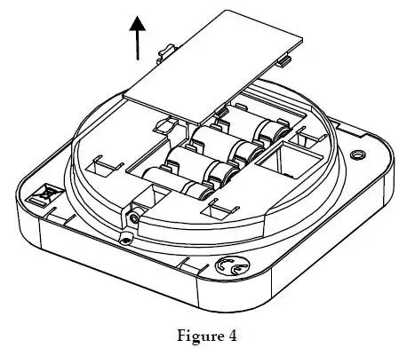
- Open the battery compartment (see Figure 4).

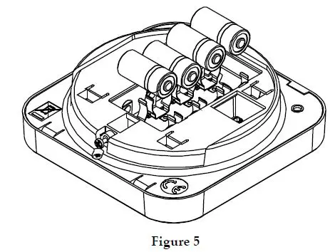
- Pull out the batteries and replace them with new ones. Pay attention to the polarity when inserting the new batteries (see Figure 5)

- Close the battery compartment and put back the keypad to its place.
Keypad Settings
Note: The following settings must be defined individually for each keypad connected to the system.
To define keypad settings when idle follow this procedure:
- Press for five seconds until the Keypad Settings menu appears.
- Select the relevant icon using the keys:
Brightness Contrast Keypad’s buzzer volume - Press
- Press the keys to adjust the level settings.
- Press to save the adjustment.
- Press to exit the keypad settings.
Technical Specification
| Power | 4xCR123 Lithium batteries |
| Current Consumption | 50mA (standby) /up to 100mA (transmission) |
| Typical Battery Life | 3 Years |
| Power Output | 10mW |
| Operating Temperature | -10 – 55°C (14 – 131°F) |
| Storage Temperature | -20 – 60°C (-4 – 140°F) |
| Humidity | Up to 75% |
| Dimensions | 214 x 110 x 35mm (8.4″H x 1.4″W x 1.1″D) |
| Color | Cream |
| Frequency | 433 MHz, 868 MHz |
Ordering Information
| Model | Description |
| E8US299KP0TA | WL Shield KP 868MHz |
| E4US299KP0TA | WL Shield KP 433MHz |
RED Compliance Statement
Hereby, RISCO Group declares that this equipment is in compliance with the essential requirements and other relevant provisions of Directive 2014/53/EU. For the CE Declaration of Conformity please refer to our website: www.riscogroup.com


