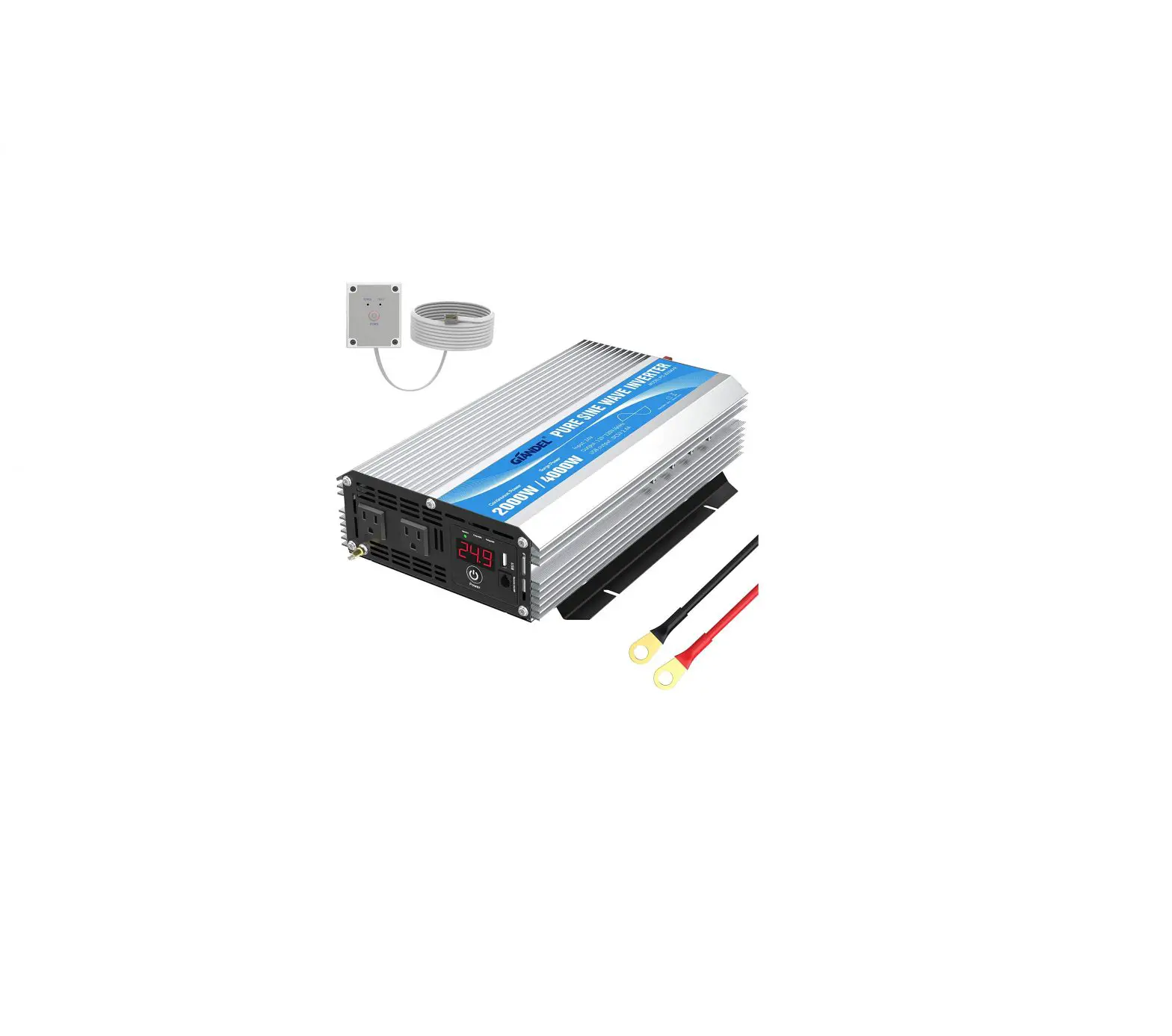
IANDEL DC to AC Pure Sine Wave Power Inverter
Specification
Item | PS-1500KAR | PS-2000KAR | PS-2500KAR | PS-3000KAR |
| Continuous power | 1500W | 2000W | 2500W | 3000W |
Surge power | 3000W | 4000W | 5000W | 6000W |
| DC input | □12V □24V | |||
| Input: Voltage range | 9.5-16V DC (rated power 12VDC) / 1 9-32VDC (rated power 24VDC) | |||
| Input over-voltage shutdown | 16VDC±0.5V / 32VDC±1VDC | |||
| Input under-voltage shutdown | 9.5VDC±0.5V / 19VDC±1VDC | |||
| Input under-voltage alarm | 9.8VDC±0.5V / 19.6VDC±1VDC | |||
| Output voltage | □ 115V/ □ 120V/ □ 220V / □ 230V / □ 240V AC+10% (Subject to the label) | |||
| Output frequency | □ 50Hz I □ 60Hz + 1 Hz | |||
| Output wave form | Pure sine wave ( THO≤3%) | |||
| Efficiency | 90 % | |||
| Over temperature protection | 65±5℃ | |||
| Over-load protection | 1500-2000W | 2000-2500W | 2500-3000W | 3000-3600W |
| USB Output | 5 VDC Max 2.1A | |||
| No Load currents | 1.2A | 2A | 2.4A | 2.4A |
| Intelligent cooling | The cooling fan on the product will not run when start up the inverter, it will start running when the case temperature reaches about 40℃ or load power is more than 40% of rated power. | |||
| Working temperature | 0~40℃ | |||
| Storage temperature | -10~45℃ | |||
| Dimension(LxWxH) | 404x240x96mm | 404x240x96mm | 504x240x96mm | 435x240x96mm |
| Weight | 5Kg | 5Kg | 6.2Kg | 5.2Kg |
BRIEF
Our power inverter is an advanced tool of power conversion, and it can supply you with AC power converted from DC power source. Not only can be used in cars, vessels and camping, but also can be used in emergency when out of electricity.
In order to use the inverter efficiently and safely, please install and use it in a proper way. Please read the instruction carefully before installing and using the appliance.
WARNING AND SAFETY
- Read the manual before use it and keep it for future reference.
- Keep away from sunshine, heating source, moisture or damp environment.
- The case of inverter will be heating up during operation, please keep away from the material that can’t stand of high temperature, such as clothes, sleeping bag and carpet.
- Our power inverter is designed to use with the negative ground electrical system!
Don’t use it with positive ground electrical systems (modern automobiles, RVs, trucks and boats are negative ground). - Do not disassemble the unit random, it may cause fire or electric shock.
- Keep inverter away from children and don’t allow them to play with the unit.
- The power inverter will output AC power as utility power, please treat the output terminal as carefully as your home AC socket. Don’t put any other things into the output terminal except electrical appliance plug. It will bring danger or fire if using in a wrong way.
- Disconnect the battery and inverter if the unit is not in use.
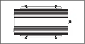
PARTS LIST
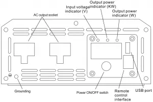
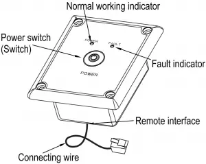
Front panel
Remote control box
ASSEMBLE
1) The position of Mounting
First ensure that there is enough space to install the inverter, while the installation location must meet the following requirements:
- Drying: Do not use water or other liquids dripping on the inverter
- Cool: a working environment temperature of the product is 0-40℃, preferably a temperature of 10-25℃, at a temperature as low as possible within this range
- Ventilation: There should be a certain distance between inverter and other objects, to avoid blocking the products vents.
- Clean: Do install the products in the dusty, wood chips or other particles , If cooling fan is turned on, the particles involved in the inside of the product, thus affecting the normal work.
- Inverters and batteries when connected, will produce arcs or sparks, so there should not be around flammable objects such as gasoline, alcohol , etc.
2) Assemble the inverter
For this big power inverter, because the heavier weight, preferably mounted on a solid platform, such as floor, table or mounting bracket fine. In order to avoid falling off, platform for supporting the product should can bear the weight of sufficient capacity, and it is good with four screws to secure the product.
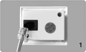
3) Assemble the remote control box
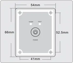
- the remote is designed to be mounted on a dash or other surface where a hole should be cut so that it sits flush. T his is not a requirement however just a recommendation.
- T he remote cable should be plugged into inverter and the remote before mounted.
Note: Optional remote is not needed for inverter operation. The main power switch will work the power on / off.
BATTERY
1). Voltage and current of the battery
The battery is designed to supply the unit with DC input voltage and the rated voltage should be in accordance with the rated input voltage of the inverter. Any voltage exceeds the range of the input voltage of the inverter will cause over voltage or under voltage protection.
In the meantime, the battery should supply sufficient current. The small capacity battery cannot drive the large power electrical appliance. In this case, the battery will be in under voltage protection because of the over-discharge of the battery. The simple calculation method of battery current is: load power divided by battery voltage. Due to the consumption of the inverter itself, the actual current will be about 10% larger. For example, the voltage of lead acid battery is 12VDC, and load power is 1000W, therefore, the actual current of the battery is about 1000W÷12V×110%≈91.6A.
2). Battery operating time
Battery operating time depends on battery capacity and current, and the calculation formula of operating time is: battery capacity divided by current, that is, battery capacity divided by the value of the load power divided by battery voltage times 110%. For example, battery specification is 12V, 2000Ah, load power is 1000W, so the total discharging time is 2000Ah÷ (1000÷12×110%) ≈21.8 hours
Notice: The result of formula above is on the basic of discharging rate of 20 hours of the battery, that is, the result is from the discharging current of 2000Ah battery not exceed 100A. When the charging current exceeds this value, the discharging period will reduce.
And the quantity of the electricity of the battery may also influence the result. See the specification of the battery manufacturer
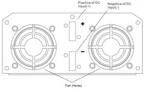
Connection
- Grounding
The power inverter has a terminal on the rear panel marked ” Grounding “or ” “. This is used to connect the chassis of the power inverter to the ground. The ground terminal has already connected to the ground wire of AC output receptacle through the internal connecting wire.
The ground terminal must be connected to the ground wire, which will vary depending on where the power inverter is installed. In a vehicle, connect the ground terminal to the chassis of the vehicle. In a boat, connect it to the boat’s grounding systems. In a fixed location, connect the ground terminal to earth.
Warnings:
● To make sure the firmness of the connection. The ground wire must be 14AWG (2.08 2 mm ) or even larger.
● Do not operate the power inverter without connecting to the ground. Electric shock may result. - Connect to the lead acid battery
(1) Please do all the safety precautions before connection, and then check whether the battery voltage is in accordance with the input voltage of the inverter. Only the voltage of the battery accords with the requirements can be allowed to connect with the inverter.
(2) The connecting wire must bear enough current. Depending on the table below, please choose the input DC wire or larger one.
Rated voltage of inverter | Current max. load power | Max. current of wire | Specification of wire length=1m | Specification of wire length: Nm |
12V | 1000W | 100A | 6AWG(13.30mm2 ) | N×13.30mm2 |
| 1500W | 150A | 4AWG(21.15mm2 ) | N×21.15mm2 | |
2000W | 200A | 3AWG(26.67mm2 ) | N×26.67mm2 | |
| 2500W | 250A | 2AWG(33.62mm2 ) | N×33.62mm2 | |
3000W | 300A | 1AWG(42.41mm2 ) | N×42.41mm2 | |
| 4000W | 400A | 1/0AWG(53.49mm2 ) | N×53.49mm2 | |
5000W | 500A | 2/0AWG(67.43mm2 ) | N×67.43mm2 | |
| 24V | 1000W | 50A | 9AWG(6.63mm2 ) | N×6.63mm2 |
1500W | 75A | 7AWG(10.55mm2 ) | N×10.55mm2 | |
| 2000W | 100A | 6AWG(13.30mm2 ) | N×13.30mm2 | |
2500W | 125A | 5AWG(16.77mm2 ) | N×16.77mm2 | |
| 3000W | 150A | 4AWG (21.15mm2 ) | N×21.15mm2 | |
4000W | 200A | 3AWG (26.67mm2 ) | N×26.67mm2 | |
| 5000W | 250A | 2AWG (33.62mm2 ) | N×33.62mm2 |
Notice:
- The table above is only for your reference. In practice, the thick wire can be replaced by two thin parallel wires if only the total cross-sectional area of the wire meets the requirements.
- In high current, the input DC wire may produce voltage drop, therefore, the operating voltage should be subject to the value on the terminals. If the voltage drop is too large, you can increase the cross-sectional area or reduce the length of the lead.
- Connect cathode wire of the battery to the cathode terminal (black) on the rear panel of inverter and then connect the anode wire of the battery to the anode terminal (red) on the inverter, and fix them.
Warnings:
- Please wear eye patch and work clothes when working around the battery to avoid the acid and corrosive objects harm your eyes and skin.
- Prepare enough water and soap. In case the acid materials contact eyes or skin, clean it by soap and water as soon as possible. If the acid materials spay to your eyes accidentally, clean it by cold water immediately and then sent to hospital.
- Do not put any combustible material in the location of installation for spark will result when it is connected to the battery.
- Keep good ventilation. The battery may produce a little inflammable gas when it works, so keep away from the inverter and it is better to install them in different space.
- Fix the connecting wire of the input DC, or it will result the over-reduction of the voltage or over-temperature of the wire.
- Reverse connection of the polarities or the short circuit will burn the fuse or result the permanence damage of the internal elements of inverter.
- Take away the metal accouterment, such as ring or watch, when installation to avoid the short circuit.
- Although there is over-voltage protection, it may also cause damage of the inverter if the input voltage is too high.
3) Connection of the AC appliance
Put the power plug of the AC appliance load into the output AC receptacle of the inverter directly.
Warnings:
- Make sure that the switches of the inverter and appliance power are in OFF position before connection.
- Check the power cord. If it is damaged, it should be connected after replacement.
4) Connection of the remote control box
Directly to the two ends of the cable respectively inserted into the inverter and wired remote control remote control box on the interface.
Usage
①. How to use inverter
- Check the output voltage and capacity of the battery to make sure it is in accord with the requirements of the product.
- Connect the battery and the DC cable of the inverter to ensure that the polarities are not connected reversely and in tight connection.
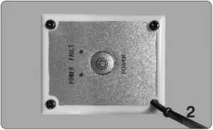
- Long press the switch or the remoter of inverter for over 0.5s and then stop, if the indicator light on the inverter or on the remote control box is on, it means that the inverter starts to work normally. This opening method can avoid turning on the unit by mistakes due to the interference or any factors.
- Switch off electrical appliances and put its plug to the AC output socket of inverter. Then switch on electrical appliance.
- The cooling fans inside the inverter do not work until the case temperature rises up to about 40℃or the load power is more than 40% of rated power.
- Switch off inverter and remoter to stop working. At that time, the indicator lights in. Both inverter and remoter are off. The inverter does not consume current of the battery when it is switched off.
②. How to use USB power supply
This model with USB output, can provide stable voltage 5V DC, maximum current 2.1A directly for the portable device with USB port.
Notice: Before using the USB power supply, please make sure the device can be charged by USB and the maximum working current is no more than 2.1A.
③.How to use solar charging
Firstly, connect battery properly, then connect the solar panels and product’s solar input terminals, make sure the positive and negative electrode of solar panel is correspondingly connected to the positive and negative terminal of solar input terminals of inverter, the indicator lights light up while charging . the user can realize the size of the battery charging voltage, when the “full” indicator lights up, indicating that the battery is fully charged, product will stop charging automatically to avoid over charge. When the battery voltage is lower, product will recover to charge automatically.
Notice: It will destroy inverter when solar charging input voltage is too high, so please choose the suitable solar panel according to the specification table .
About soft start technology
The output voltage rises up from low to normal when the inverter is turned on. This can reduce attack of high startup currents, which can make startup easier of large inductive loads.
As for the large inductive loads, such as electric tools and the capacitive loads, suggest turning on the switch of the appliance firstly and later the inverter’s. The soft start works.
The output wave form
The output wave form of this inverter is Pure Sine Wave, which is much like the one from utility-supplied AC electricity, even more purer; pure sine wave is applicable in most of loads, including electrical equipments, such as Linear Adaptor, switching power supply, transformer, and motor and so on.
Comparing with Modified wave form, for inductive loads such as refrigerator and electric fans, pure sine wave form can improve its power factor and the battery’s efficiency and reduce working noises effectively from appliances. For capacitive loads such as adapter of lap-top, pure sine wave can lower the rush current at work and reduce interferences to increase reliability and prolong the life of the product.
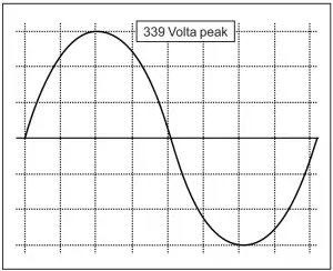
Pure sine wave output (240 VAC Model)
Work Instructions
When the inverter is in work condition, the input voltage and output power will be shown on the digital display screen by turns. Likewise, when the inverter goes into protection, corresponding letters will be also shown on the screen. Different letters mean the inverter is in different protection conditions.
- When the input (V) LED is on, the current input voltage is shown.
- When the output (KW) LED is on, the current output power(KW)is shown.
- When the output (W) LED is on, the current output power(W)is shown.
- LO means the inverter is in under voltage protection.
- HI means the inverter is in over voltage protection.
- OL means the inverter is in overload protection or short-circuits protection.
- OH means the inverter is in OVER HEAT protection
Protection Function
- Input under-voltage alarm: When the input DC voltage is lower than 9.8V /19.6V/39.2V, the buzzer will whistle intermittently to remind that the inverter will go into the under voltage protection. Pay attention to save the data if you are using computer.
- Under voltage protection: The inverter will automatically shut down when the input DC voltage is lower than 9.5V/19V/38V. The buzzer will whistle continuously and the digital display screen will show LO. Please turn off the inverter and use it after recharging the battery.
- Over voltage protection: The inverter will automatically shut down when the input DC voltage is higher than 16V/32V/62V. The buzzer will whistle continuously and the digital display screen will show HI. Please turn off the inverter and adjust the input voltage to the admissible range.
- Overload protection: The inverter will automatically shut down when the load power is higher than the rated power. The buzzer will whistle continuously and the digital display screen will show OL. Turn off the inverter and resume to normal operation after taking away the redundant load.
- Short-circuit protection: The AC output will be automatically shut down when short circuit. And the digital display screen shows OL. It will automatically restored after the problem solved.
- Thermal protection: The unit will be calorific during operation. If the temperature is higher than 65 , the inverter will automatically shu ℃ t down. Then the buzzer will whistle continuously and the digital display screen shows OH. Please turn off the inverter, and continue using it after the temperature goes back to normal temperature naturally. Meanwhile find out the factors causing the fault, such as ventilation, ambient temperature, vent, load power and so on. It can avoid the similar things happen again.
FAILURE GUIDELINES
Fault/Display | Cause | Solutions |
| No output voltage, buzzer whistles continuously | Low input DC voltage | Recharge or replace the battery. |
| High input DC voltage |
| |
| Overload | Reduce the load power. | |
| Over temperature |
| |
| No output voltage |
|
|
| Incorrect output voltage |
|
|
| Cannot drive the load |
| Reduce the load power, or open the appliance first, then open the inverter, The inverter internal soft-start circuit to buffer start the appliances. |
| Snowflakes on the screen or noise of the audio | Disturbance |
|
If the unit still doesn’t work normally after using all the methods above, it maybe the internal faults of the circuit. Please return it to the supplier for maintenance.
Warranty
We take the guarantee of one year from the purchasing day. During the guarantee period, any malfunction caused by our product quality, our company will fix or replace the unit for free. But any one of the following conditions is beyond our guarantee terms.
- The box distorted, damaged or changed, and interior parts damaged because of the exterior hit or drop.
- Connect the DC power adversely.
- Dismantled or repaired the unit by un-granted person.
- The unit was damaged by incorrect installation or operating method.
Service support: [email protected]


