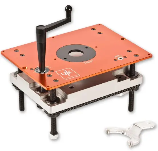
ujk 502701 Router Elevator
This product has been wholly designed by AxminsterTool Centre Limited who have exclusive use of the design. As such it should not be copied or reproduced.
Please dispose of packaging for the product in a responsible manner. It is suitable for recycling. Help to protect the environment, take the packaging to the local recycling centre and place into the appropriate recycling bin.
The symbols below advise the correct safety procedures when using this machine.
| Quantity | Item | Model Number | |
| 1 No. | Router Elevator with Measurement Dial (router mounting plate and table Insert fitted) | A | 502701 |
| 1 No. | Winding Handle | B | |
| 1 No. | Packet containing:- | ||
| 6 No. | M6 Grub Screws | C | |
| 2 No. | M6 Countersunk Bolts | D | |
| 1 No. | Nippled ‘Y’ wrench (for Table Insert) | E | |
| 4 No. | Hex Keys 6mm/4mm/3mm/2.5mm | F |
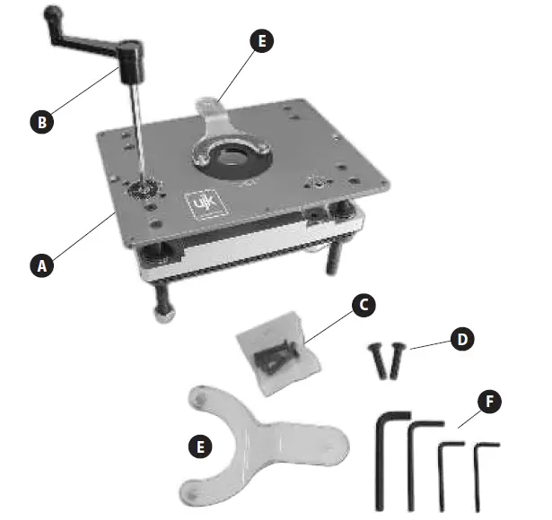
WHAT’S INCLUDED
Having unpacked your machine and its accessories, please check the contents against the equipment list
”What’s in the box”, if there are any discrepancies, please contact Axminster Tool Centre using the procedures laid down in the catalogue. Please dispose of the packaging responsibly; much of the material is bio-degradable.
Please read the Instruction Manual prior to using your new tool; there are daily and periodic maintenance recommendations to help you keep your machine on top line and prolong its life. Keep this Instruction Manual readily accessible for any others who may also be required to use the machine.
Please read through the section entitled Identification and Description of Parts, so that you will be familiar with the terminology we will use in the manual, and so that you can identify the parts quickly and easily.
SPECIFICATIONS
- Code 502701
- Machine Table Size 306mm x 229mm x 6mm
- Rise and Fall Platform Size: 275mm x 200mm
- Router Mounting Plate Circular Universal Type
- Maximum Rise and Fall 100mm
- Rise and Fall Linear Movement per turn 2mm
- Floating Measurement Dial Graduation 0.125mm
- Centre Hole Diameter (Without insert ring) 92mm
- Centre Hole Diameter in Insert Ring 38mm
- Centre Hole in Rise and Fall Platform 75mm
- ‘Lost’ Cutter Length (from router mounting plate to machine table) 14.5mm
- Overall Size L x W x H L 306mm x W 229mm x H 165mm
- Weight 6 kg
ACCESSORIES
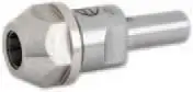 Axcaliber Router Collet Extension (1/2” Shank) (Code: 211367)
Note: The Assembly requires a through table void of 280mm x 205mm. The recess for the Machine Table is 306mm + 229mm + 6mm + deep. The dimensions and the position are shown on the next page (See Fig A)
DIMENSIONS POSITION DIAGRAM
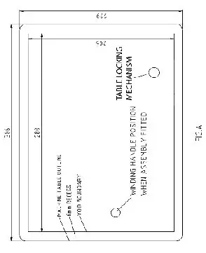
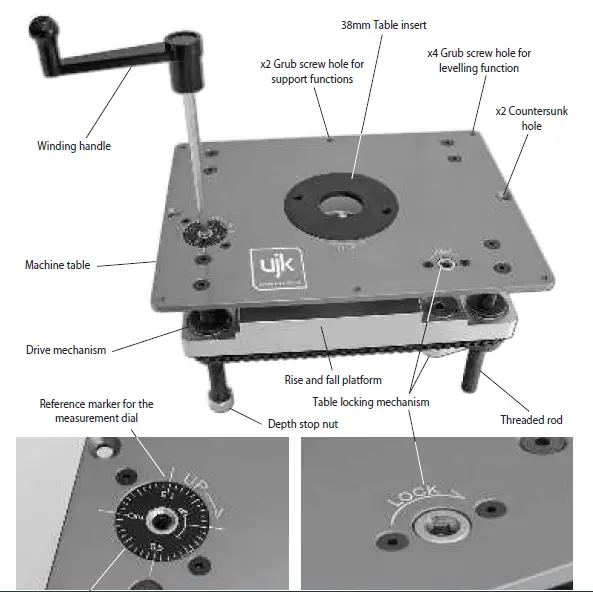
ILLUSTRATION & DESCRIPTION OF THE ROUTER ELEVATOR
FITTING THE ROUTER AND THE CUTTERS
INTRODUCTION
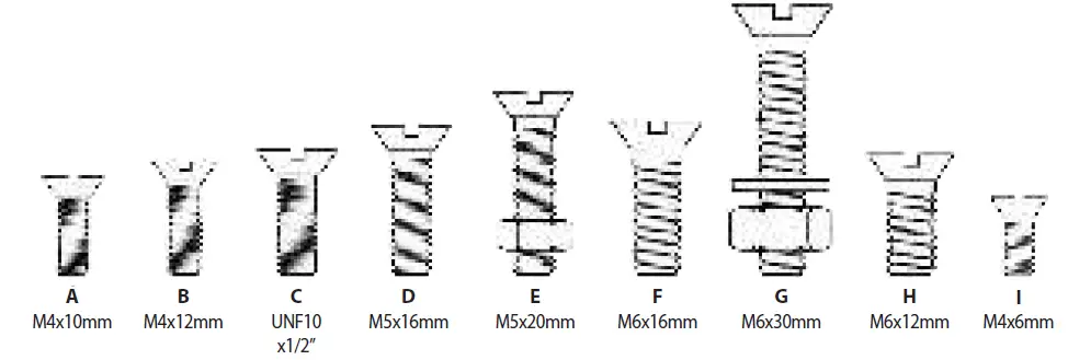
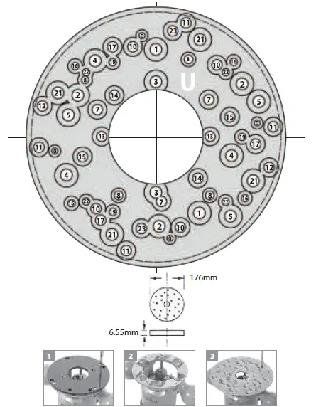
The information below is reproduced from the Axminister universal base plate fitting instructions and the hole layout on the router elevator base plate is identical. Hole numbers, screw types and how many required are given for mounting different router models to the router elevator base plate. For advice on models suitable for fitting to the router elevator please contact our experts on 03332 406 406
Please note: Some of the router’s listed in this chart may not be suitable for use with the router elevator.
| BOSCH | 1700ACE POF52, | 1 | Fx2 |
| 400,500A,600ACE | 3 | Fx2 | |
| POF800ACE.GOF900A <2003 | 4 | Gx3 | |
| GOF1300ACE,900A>2003 | 5 | Gx3 | |
| GMF1400 | 0 | Ix4 | |
| CMT | CMT1E,CMT2E | 1 | Fx2 |
| DEWALT | DW613,614,615,620,621, DW625EK.629 | 1 | Fx2 |
| DRAPER | R1900V | 2 | Fx3 |
| PT1200V | 1 | Fx3 | |
| ELU | OF97(E),MOF177(E), 131,98, MOF77,96(E) MK2,69’ | 1 | Fx2 |
| FELISATTI | R346EC | 1 | Ex2 |
| FESTOOL | OF2000(E) | 7 | Ex3 |
| OF1E,900(E),1000(E), OF1010 | 8 | Bx4 & Ax3 | |
| OF1400 EBQ-Plus | 23 | H2 | |
| FREUD | FT1000(E),2000E | 2 | Fx3 |
| HITACHI | M8(V) | 10 | Dx4 |
| M12V,M12SA | 11 | Dx4 | |
| TR12 | 11-12 | Dx4 |
| HIKOKI | M12VE | 11 | Dx4 |
| MAFELL | L050E | 8 | Bx4 |
| MAKITA | 3620,3612BR,3600B | 13 | Dx2 |
| 3612(C) | 14 | Ex2 | |
| RP0910,1110C | 1 | Fx2 | |
| RP2301FCX | 22 | Bx4 | |
| PRO | CLM1250R >11/03,CLM2050R | 1 | Fx2 |
| PERLES | OF808(E)>1999’,2-808(E), OF9(E) | 1 | Hx2 |
| PEUGEOT | DEF570E.DF55E | 15 | Ex2 |
| RYOBI | RE600N,R600N,RE601, ERT1500V | 13 | Dx2 |
| R500,502 | 16 | Ax4 | |
| R150,151,RE120,155K | 15 | Ex2 | |
| SKIL | 1835U.1875U1 | 17 | Cx3 |
| TREND | T3,T4,T5,T5MK2’ ,T9,T10,T11, (Not suitable for the T7EK) | 1 | Hx2 |
| TRITON | MOF001 TRA001 | 21 2 5 | 1/4″ UNC 6.35mm |
| WADKIN | R500 | 16 | Ax4 |
FITTING THE ROUTER AND THE CUTTERS
UNIVERSAL BASE PLATE
IN ORDER TO FIT SOME OF THE ROUTERS TO THE ELEVATOR AND ACHIEVE UNRESTRICTED MOVEMENT, IT MAY BE NECESSARY TO REMOVE THE HANDLES; PLUNGE THE ROUTER BODY TO DEPTH, ETC., ETC.
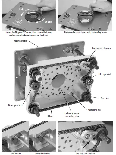
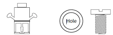
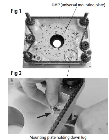
Lower the table to almost its fullest extent. Using the Allen key provided loosen the bolts and therefore the lugs holding the universal mounting plate (UMP) in position and remove. (See Figs 1 and 2). Remove the sole plate from your router, see illustrations 1 to 2 and secure your router to the UMP via the appropriate holes, see pages 8-9. Insert the requisite tool into the router and tighten securely.
Adjust the ‘depth’ of the router to give the slightly more than the required exposure of the tool (to allow for adjustment) and lock the body. Remember that you will loose 14.5mm of the set ‘height’ of the cutter between the lower face of the universal mounting plate and the upper surface of the machine table. Alternatively, current practise would indicate that the router is plunged to maximum depth and all height adjustment is done using the elevator. Refit the mounting plate to the rise and fall platform. (See Fig 3)
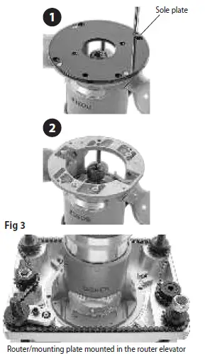 Router/mounting plate mounted in the router elevator
Please note: Removing the router handles will prevent them from interfering with the chain.
Re-fasten the holding lugs. If the router tool diameter is greater than 75mm, the router/mounting plate combina-tion must be refitted to the rise and fall platform first, and then the tooling mounted into the router. (Hint. You will find this easier with the rise and fall platform at its highest position and the table insert removed).
NOTE. If you find that some of your cutters are ‘borderline’ for ‘reach’ or the length of shank remaining in the collet is approaching the minimum limit, may we suggest the purchase of the short collet extension Axminster No. 211367. (See Page 4)
NOTE. If you are not using a professional router table with a remote On/Off switching facility, or a Power Tool NVR Switch, remember to orientate the router so that the power switch is easily accessible when the router elevator is fitted to the work platform.
When everything is assembled to your satisfaction. Check the speed setting of the router is correct for the cutter diameter. Give the router a ‘quick burst’ to check that everything is secure. If the ‘quick burst’ check is O.K. Proceed to fit your fencing, dust extraction etc
SETUP/OPERATING INSTRUCTIONS
Ensure you have identified all the parts of your Router Elevator.
Place the Router Elevator into the prepared recess. (See Fig A on page 05). Check that it is flush with the work platform surface. If this is not the case insert the supplied grub screws in the threaded corner holes and level the machine table. (See Fig 4) If, for some reason, it is impossible to level the table absolutely flush with the work platform, ensure that the ‘front’ of the table is low in the recess, and the ‘rear’ of the table is high to the work surface. (Low and High in this instance refer to the minimal measurements required to ensure that there is no ‘edge’ for the work piece to ‘snag’ on). When you are satisfied with the levelling process you can, if required, fasten the elevator in position with the two M6 bolts supplied or even two Wood Screws. (perhaps an MDF working platform/table?). 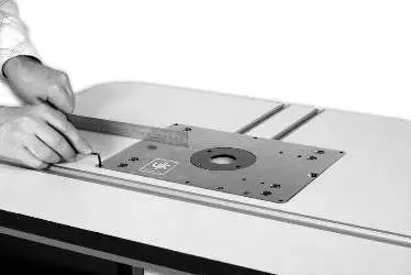
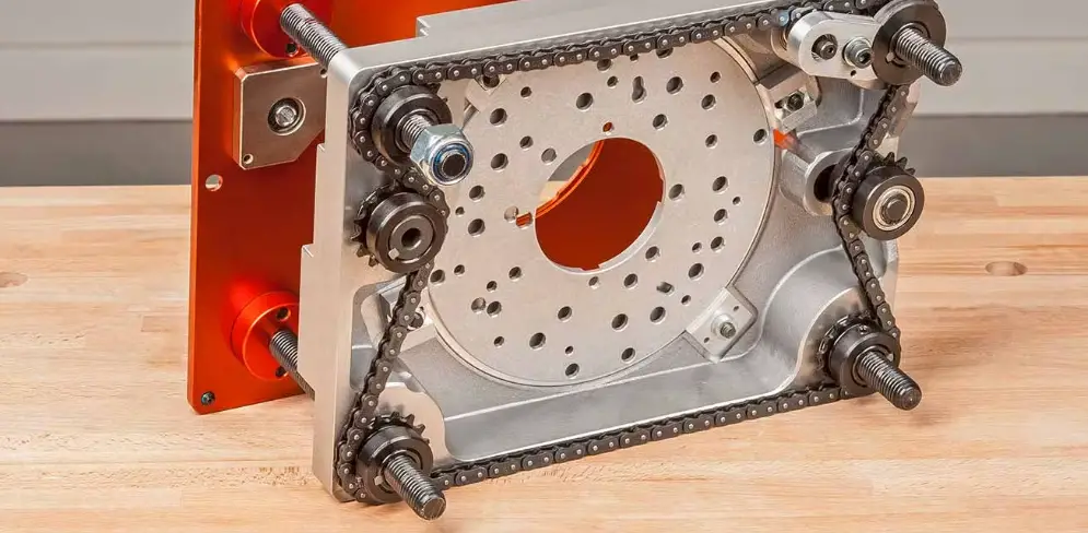
MAINTENANCE
The router elevator requires minimum maintenance, but you are advised to observe the following points:-
- Keep the elevator clean. Ensure that dust/chips etc., are cleaned away at the end of a work session.
- Do not allow a build up of dust/chips etc., between the machine table and the rise and fall platform, or under the machine, where it may foul the chain drive.
- If the winding action becomes ‘lumpy’ check that there is no debris caught in the chain, or compressed onto a sprocket.
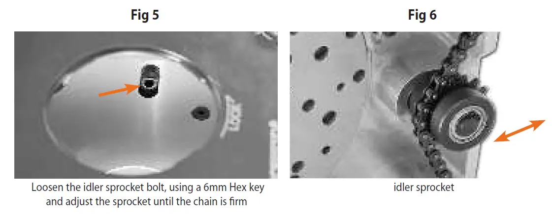
- Check the chain tension. If the chain has become ‘slack’ or loosened, re-tension by adjusting the idler sprocket. Do not over tension, the chain needs to be firm, with a small side to side movement (best checked on a ‘long’ side) it does not need to be rigid. (See Figs 5 and 6)
- Remember! A chain is a machine as well, give it a light lube.
EXPLODED DIAGRAMS/LISTS
EXPLODED DIAGRAMS/LISTS
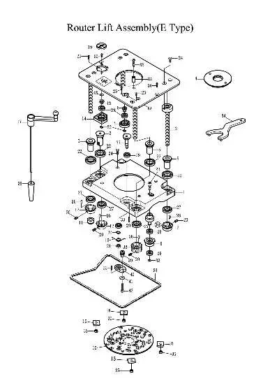
| Index | Part No | Description | Size | Qty |
| 1 | 60700001 | Aluminum Carriage Bracket | 1 | |
| 2 | 60500002 | Main Gear Shaft | 1 | |
| 3 | 60500003 | Lead Screw | 4 | |
| 4 | 60100017 | Insert Ring | 1 | |
| 5 | 60500005 | Gear Shaft | 4 | |
| 6 | 60500006 | Upper Guide Nut | 1 | |
| 7 | 60700008 | Upper Guide Nut Base | 1 | |
| 8 | 60700007 | Top Table | 1 | |
| 8A | 60700031 | Starter Pin | 1 | |
| 8B | 906M06025 | Round Head Screw | M6 x 25 | 1 |
| 9 | 60500009 | Cam Gear | 1 | |
| 10 | 60700010 | Wheel Elliptic | 1 | |
| 11 | 912M14000 | Nylon Nut | M14 | 1 |
| 12 | 60500012 | Chain Gear | 4 | |
| 13 | 60700017 | Base | 1 | |
| 14 | 60700001 | Upper Guide Nut | 1 | |
| 15 | 60500015 | Master Ring | 1 | |
| 16 | 60500016 | Master Ring Clamp | 4 | |
| 17 | 60700009 | Lift Handle | 1 | |
| 18 | 60700003 | Spring | 1 | |
| 19 | 60700018 | Scale Plate | 1 | |
| 20 | 908M06006 | Set Screw | M6 x 6 | 9 |
| 21 | 923688ZZ | Ball Bearing | 688ZZ | 1 |
| 22 | 9236805Z0 | Ball Bearing | 6805ZZ | 5 |
| 23 | 901M08020 | Hex Socket Cap Screw | M8 x 20 | 1 |
| 24 | 903M06018 | Flat Head Cap Screw | M6 x18 | 12 |
| 25 | 903M04012 | Flat Head Cap Screw | M4 x12 | 4 |
| 26 | 9180404018A | Key | M4 x 4 x 12 | 5 |
| 27 | 9236804Z0 | Ball Bearing | 6804ZZ | 5 |
| 28 | 60700009B | Crank Handle Sleeve | 1 | |
| 29 | 9236900Z0 | Ball Bearing | 6900ZZ | 6 |
| 30 | 903M06030 | Flat Head Cap Screw | M6x30 | 2 |
| 31 | 60700020 | Chain | 1 | |
| 32 | 919S01000 | C-Ring | S10 | 4 |
| 33 | 917M03018 | Lock Pin | M3 x 18 | 3 |
| 34 | 60100018 | Insert Wrench | 1 | |
| 35 | 910M06000 | Hex Nut | 1/4” | 4 |
| 37 | 60700005 | Eccentric Rod | 1 | |
| 38 | 60700012 | Brake Gear | 1 | |
| 39 | 60700006 | Lock Arm Spacer | 1 | |
| 40 | 60700013 | Lock Arm | 1 | |
| 41 | 914M061301 | Flat Washer | M6 | 1 |
| 42 | 901M06030 | Hex Socket Cap Screw | M6 x 30 | 1 |
| 43 | 94300002 | O-Ring | 1242 x 178 | 1 |
The UJK technology brand was launched by Axminster in 2012 with the intention of encompassing a range of carefully selected products that Axminster held in particular high esteem. Many of these products are designed by and manufactured by Axminster. The range includes routing, measuring and wood jointing products and has proven to be extremely popular. Axminster continually strive to develop and increase the range of quality, innovative products.
Axminster Tools, Axminster, Devon, EX13 5PH
axminstertools.com/ujk


