![]() Key Components for Analytical Instrument
Key Components for Analytical Instrument
Ecological Closed-loop Supplier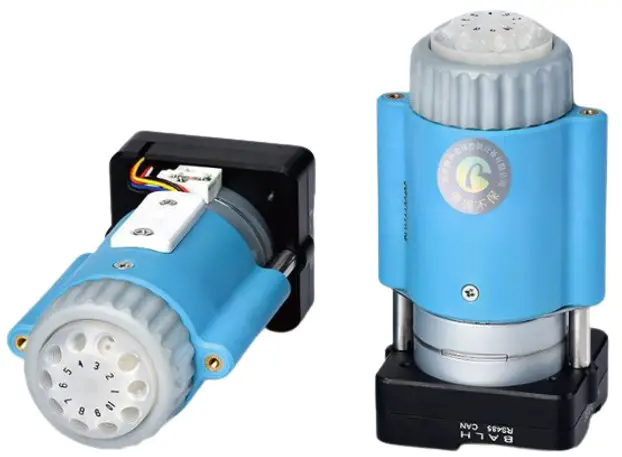
V 1.2
Smart SV-04B Injector Valve Manual
NANJING RUNZE FLUID CONTROL EQUIPMENT CO.,LTD
Thank you very much for choosing our product, please read and keep this manual carefully before use
Chapter1 Getting Started
Company Profile
Nanjing Runze Fluid Control Equipment Co., Ltd. was established in 2014, We are a national high-tech enterprise focusing on R&D and production of fluid accessories for numerous analytical instruments. We engineer, manufacture and market differentiated standard products such as syringe pumps, multiport valves, peristaltic pumps, gastight syringes, plastic fittings, etc.. We persevere in providing our customers with best quality and service in the fields of environmental monitoring, biopharmaceuticals, medical equipment, industrial automation and laboratory instruments, etc.
RUNZE attracted experienced talents with strong capability on integrating software and hard-ware at electronic research, mechanical design, mold manufacturing. In past years, we have accumulated rich technical and practical experience that bring us honors of ISO9001, National High-tech Enterprise, Jiangsu Province Private Science and Technology Enterprise, 5A Bank Credit Assessment, 38 technical patents and multiple software copyright including 8 invention patents, 17 utility model patents, 13 design patents.
RUNZE Technology Center has a reliable EMC laboratory and a series of advanced processing equipment and testing instruments, such as imported white light interferometer, Keens plane rapid detector, five-axis machining center, high-precision nano-grinding machine, etc., Continuous and substantial investment in research and development, which enabled the company to obtain a huge advantage in the manufacture and sales of analytical instrument accessories.
Chapter2 Product Introduction
Product Features
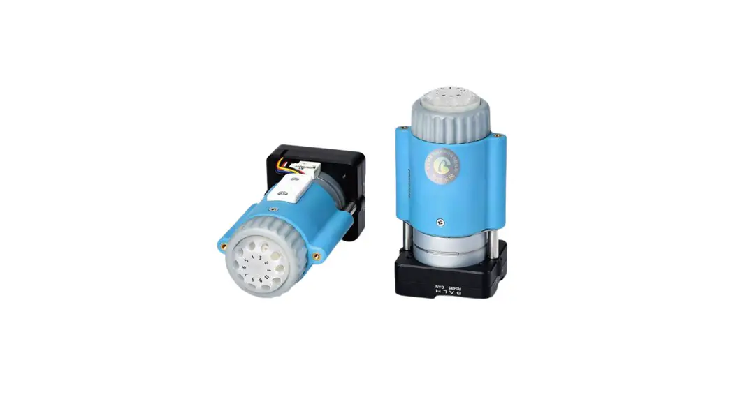
- Name: The injector valve is an electric injector valve independently developed by RUNZE Fluid Control Equipment Co., Ltd., also known as electric rotary valve;
- Control: By receiving instructions from the host computer to control the operation of the stepper motor to make the rotor turn to the specified port position to achieve the switching of the flow path. Serial communication protocol supports RS232/RS485/CAN bus.
- Corrosion Resistance: This type of injector valve adopts sapphire valve core, which can be applied to various corrosive liquids. The valve head are made of PCTFE (polychlorotrifluoroethylene) and PPS, maintenance-free;
- Valve Core Structure: The valve core adopts a multi-directional self-adaptive plane fitting method, which can extend the service life of the product effectively. (This structure has been applied for utility patent, patent number: CN204852471U)
- Motive power: The rotation of the valve body adopts the imported NMB planetary gearbox motor as the power plant, which is extremely reliable.
- Orientation: The valve hole is oriented by optical encoder, which can effectively solve the problem of inaccurate positioning after the gearbox is worn down.
- Driver: The two-phase bipolar stepper drive module is a constant current drive chip, which can control the motor current with high efficiency. It has a built-in error detection circuit and error detection (TSD/ISD) signal output function;
- Control Unit Interface: XH terminal with 2.54mm pitch
- Mechanical Interface: 1/4-28UNF internal thread
- Usage: Widely used in the collection and distribution of fluid samples
- Application: Environmental testing devices, experimental analysis instruments, medical analyzers, chromatographic instruments, etc. Before using the injector valve, please read the “Instruction Manual” carefully and follow the provisions in it.
Naming Rules
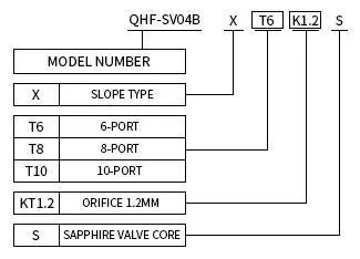
Figure 2-2
Example: Slope type 10-channel sapphire injector valve, naming: QHF-SV04B-X -T10-K1.2-S
Product Specification
Smart SV-04B injector valves can be divided into 6 ports, 8 ports, and 10 ports according to the number of channels, as shown in the figure below:
 Figure 2-3
Internal Structure
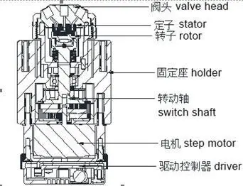
Figure 2-4
Dimension (unit: mm)
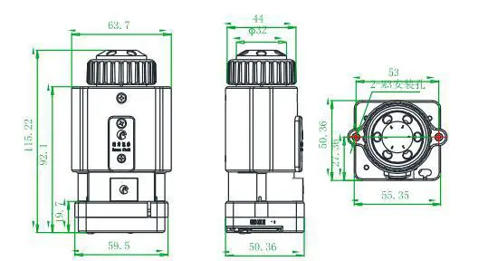 Figure 2-5
Note: 6 ports/8ports/10ports valve share the same dimension.
Technical Parameters
| Description | Parameter | ||
| Configuration | 6 port | 8 port | l0 port |
| Orifice | 1.2mm | ||
| Wetted material | PCTFE valve head, Sapphire rotor/stator | ||
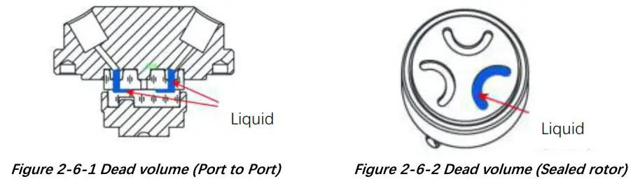
| Dead volume (Port to Port) | 28.121pL | 28.67pL | 28.129pL |
| Dead volume (Sealed rotor) | 5.207pL | 5.756pL | 5.215pL |
| Pressure rating | 0-0.3Mpa (air) / 0-0.6Mpa water) | ||
| Origin detection | Auto reset to initial position when powered on (this function can be opened or closed) | ||
| Liquid temperature | 0-150C° | ||
| Connection | 1/4-28UNF | ||
| Replaceable parts | Stator replaceable, sealed rotor irreplaceable | ||
| Transposition | Random start to any specific port | ||
| Driver | Non-optional | ||
| Valve switching time | E 4s/circle | ||
| Max. torque | 4N/m | ||
| Communication | RS232/RS485/CAN | ||
| Baud rate | RS232/RS485: 9600bps, 19200bps. 38400bps, 57600bps, 115200bps CAN: 100Kbps. 200Kbps, 500Kbps, 1Mbps | ||
| Address & Parameter setting | Via communication | ||
| Power supply | DC24V/1A | ||
| Max. power | 24W | ||
| Operating temperature | 0C-50C° | ||
| Operating humidity | <80% relative humidity, non-condensing | ||
| Dimension (L•W.H) | 63.7*50.4.115.2mm | ||
| Net weigh | 0.437kg | ||
Flow configuration
Center port is the public port, valve can switch to any specific port by programmable control via RS232/RS485/CAN communication.
Flow configuration is shown as below:
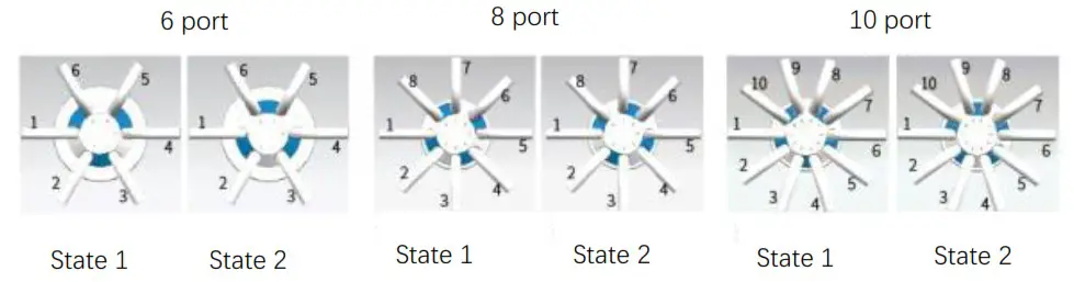
Figure 2-7
SV-04B Reset direction: CCW (Unchangeable)
SV-04B Reset position: State 1(as shown in Figure 2-7)
Port Definition
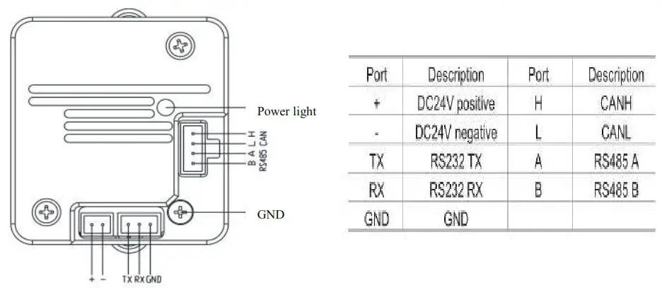
Figure 2-8 Port Definition of Driver Board
Chapter3 Description of Control Code
Overview
The data transmission between the injector valve and the host device (computer, single-chip computer, PLC, etc.) adopts serial communication (eg: RS-232/RS-485/CAN bus), the following describes the communication format: the communication adopts asynchronous serial communication, Commands and data frames use sum check, and the sum check is two bytes (2Byte). Commands and data in communication are in hexadecimal number, parameters are stored in little-endian mode.
Other instructions:
Communication interface: RS-232, RS-485, CAN bus;
Communication mode: two-way asynchronous, master-slave mode;
Baud rate:RS-232/RS-485: 9600bps, 19200bps, 38400bps, 57600bps, 115200bps;
CAN: 100Kbps, 200Kbps, 500Kbps, 1Mbps;
Data bits: 8 bits;
Parity: none check.
Response time <1 second after receiving the command.
Installation and Debugging
- Installation and debugging tools, see 《Instructions for Debugging Tools》for details
- Instructions for use, see 《Smart SV-04B Quick Use Guide》for details
Code Instructions
Control Command Format
a: Valve parameter setting command (factory command)
b: Valve parameter query command (common command)
c: Valve action command (common command)
Figure3-3-1 Send Command (common command)
Interpretation of 0xXX: 0x means hexadecimal, XX is a two-digit hexadecimal number. The value inputted into the software all should be XX.
The message frame of “Send Command” is 8 bytes, and the complete format is as follows:
| Start code | Address code | Function code | Parameters | End code | Sum check | ||
| BO | B1 | B2 | B3 | B4 | B5 | B6 | B7 |
| STX | ADDR | FUNC | 1-8 bit | 9-16 bit | ETX | Low byte | High byte |
1st byte “STX” = Start code (0XCC)
2nd byte “ADDR” = Address of slave device (0x00~0x7F) Multicast Address (0x80~0xFE) Broadcast Address (0xFF)
3rd byte “FUNC” = Function code
4th and 5th byte = Parameters of function code
6th byte ETX= End code (0xDD)
7th and 8th byte = Sum check code from byte 1 to 6
Note: The above command format refers to the common command. In particular, if a password bit is added to the factory command and the parameter bit has also changed, from the original 2 bytes to 4 bytes, the command format is as follows:
The message frame of “Factory Command” is 14 bytes, and the complete format is as follows:
Figure3-3-2 Send Command (Factory Command)
| Start code | Address code | Function code | Password | Parameters | End code | Sum check | ||||
| BO | B1 | B2 | 63.64.65.66 | B7 | B8 | B9 | B10 | B11 | B12 | B13 |
| STX | ADDR | FUNC | PWD | 1-8 bit | 9-16 bit | 17-2 4 bit | 25-3 2 bit | ETX | Low byte | High byte |
Figure3-3-3 Response Command
| Start code | Address code | Status code | Parameters | End code | Sum check | ||
| BO | B1 | B2 | B3 | B4 | B5 | B6 | B7 |
| STX | ADDR | STATUS | 1-8 bit | 9-16 bit | ETX | Low byte | High byte |
Note: The send command & response command format for the common commands are the same, and all the response command message frames are 8 bytes.
Command Format Instructions
Definition of Start Code & End Code B0B5(B11)
| Item | Code | Remark |
| Start code B0 | 0XCC | |
| End code B5 (B11) | 0xDD |
Note: The send command & response command of the common command are the same. The start and the end code are B0 and B5 respectively. The factory command is B11.
Definition of Address Bit B1:
| Item | Instruction | Code B1 | Remark |
| Address Bit | Address | 0xXX |
Note: 1. The send command is the same as the response command 2 The XX in “0xXX” means that it can be set, the factory default is 0x00, and the parameter value range is 0x00~0x7F.
Figure3-3-4 Control Command Instructions(B2~B10)
a: Valve parameter setting command (factory command) (B2~B10)
| Command Code B2 | Command Instruction | Code (B3. B4. B5. B6) | Parameters Instructions (B7, B8. B9. B10) |
| 0x00 | Set address | B3=OxFF B4=0xEE B5=OxBB B6=OxAA | B7=0xXX (B8=0x00 B9=0x00 B10=0x00) The value range of XX is 00 – 7F in V1.9 & above version, 00 – FF in version below V1.9, default value is 00 |
| Ox01 | Set RS232 Baud rate | B3=0xFF B4=0xEE B5=OxBB B6=OxAA | Totally 5 baud rates: the factory default is 9600bps (B8=0x00 B9=0x00 B10=0x00) B7=0x00 corresponds to a baud rate of 9600bps B7=0x01 corresponds to a baud rate of 19200bps B7=0x02 corresponds to a baud rate of 38400bps B7=0x03 corresponds to a baud rate of 57600bp s B7=0x04 corresponds to a baud rate of 115200bps |
| 0x02 | Set RS485 Baud rate | B3=OxFF B4=OxEE B5=OxBB B6=OxAA | |
| 0x03 | Set CAN Baud rate | B3=OxFF B4=OxEE B5=OxBB B6=OxAA | Totally 4 baud rates: the factory default is 100K (B8=0x00 B9=0x00 B10=0x00) B7=0x00 corresponds to a baud rate of 100Kbps B7=0x01 corresponds to a baud rate of 200Kbps B7=0x02 corresponds to a baud rate of 500Kbps B7=0x03 corresponds to a baud rate of 1Mbps |
| OxDE | Set automatic reset when power-on | B3=OxFF B4=OxEE B5=OxBB B6=OxAA | B7=0x00 means non-automatic reset B7=0x01 means automatic reset Automatically reset to state 2 after power-on (the factory default of injector valve is automatic reset) |
| Ox10 | Set CAN destination address | B3=OxFF B4=OxEE B5=OxBB B6=OxAA | B7=0xXX (B8=0x00 B9=0x00 B10=0x00) The value range of XX is 00 – FF, and the default is 00 |
| 0x50 | Set address of multicast channel 1 | B3=OxFF B4=0xEE B5=OxBB B6=OxAA | B7=0xXX (B8=0x00 B9=0x00 B10=0x00) The value range of XX is 80 – FE, and the default is 00 |
| 0x51 | Set address of multicast channel 2 | B3=0xFF B4=0xEE B5=OxBB B6=OxAA | B7=0xXX (B8=0x00 B9=0x00 B10=0x00) The value range of XX is 80 – FE, and the default is 00 |
| 0x52 | Set address of multicast channel 3 | B3=OxFF B4=OxEE B5=OxBB B6=OxAA | B7=0xXX (B8=0x00 B9=0x00 B10=0x00) The value range of XX is 80 – FE, and the default is 00 |
| 0x53 | Set address of multicast channel 4 | B3=OxFF B4=OxEE B5=OxBB B6=OxAA | B7=0xXX (B8=0x00 B9=0x00 B10=0x00 The value range of XX is 80 – FE, and the default is 00 |
| OxFC | Parameter lock | B3=OxFF B4=OxEE B5=OxBB B6=OxAA | All the parameters are Ox00 |
| OxFF | Restore factory settings | B3=OxFF B4=OxEE B5=OxBB B6=OxAA | All the parameters are Ox00 |
Example: Use the 0x50/51/52/53 command to set the multicast address (only uses 0x50/51/52 three commands in this example)
Use three sets of SV04B injector valves with the same software version. In the RS485 communication mode, set their addresses to 00, 01, 02 and make a mark. Firstly, Set parameter 0x81 of SV04B multicast channel 1 address marked as 00 to 81 by the command 0x50, set parameter 0x81 of multicast channel 2 address to 81 by command 0x51; Set parameter 0x82 of the multicast channel 1 address of SV04B marked as 01 to 82 by command 0x51, and the parameter 0x82 of multicast channel 2 address is set to 82 by command 0x52. Set parameter 0x83 of the multicast channel 1 address of SV04B marked as 00 to 83 by command 0x50, and the parameter 0x83 of multicast channel 3 address to 83 by command 0x52 (See the table below for details)
| Device Item | Devicel (address 0) | Device2 (address 1) | Device3 (address 2) |
| Multicast address | 81(2) | 81(2) | |
| Broadcast address | FF(1) | FF(1) | FF(1) |
| Multicast address | 82(2) | 82(2) | |
| Broadcast address | FF(1) | FF(1) | FF(1) |
| Multicast address | 83(2) | 83(2) |
After the setting is completed, connect the three devices in parallel to the serial debugging tool, and use our debugging tool MotorTest V0.8 for debugging. In MotorTest V0.8, set the address to 0x81, the command to 0x44 and the parameter to 0x02, click to send and then the device 1 and device 2 will have port switching action; Set the address to 0xFF ,the command to 0x44 and the parameter to 0x01, click to send and then the device1.2 3 will all have port switching action; Set the address to 0x82, the command to 0x44, and the parameter to 0x02, click send and then the device 2 and device 3 will have port switching action; Set the address to 0xFF, the command to 0x44, and the parameter to 0x01 , click to send and then the device1.2 3 will all have port switching action; Set the address to 0x83, the command to 0x44, and the parameter to 0x02 , click to send and then the device1 and device 3 will have port switching action;
The newly added command to set the multicast address greatly meets the needs of customer groups, making it easier and more convenient for customers. You can choose the device you want to control so that you can complete your work more efficiently and quickly during usage.
b: Valve parameter query command (common command) (B2~B4)
| Command Code B2 | Command Instruction | Response Parameter (B3, B4) |
| 0x20 | Query Address | B3=0x00 B4=0x00 |
| 0x21 | Query RS232 baud rate | B3=0x00 B4=0x00 |
| 0x22 | Query RS485 baud rate | B3=0x00 B4=0x00 |
| 0x23 | Query CAN baud rate | B3=0x00 B4=0x00 |
| 0x2E | Query Automatic reset when power on | B3=0x00 B4=0x00 |
| 0x30 | Query CAN destination address | B3=0x00 B4=0x00 |
| 0x70 | Query multicast channel 1 address | B3=0x00 B4=0x00 |
| 0x71 | Query multicast channel 2 address | B3=0x00 B4=0x00 |
| 0x72 | Query multicast channel 3 address | B3=0x00 B4=0x00 |
| 0x73 | Query multicast channel 4 address | B3=0x00 B4=0x00 |
| 0x3E | Query current channel address | B3=0x00 B4=0x00 |
| 0x3F | Query current version | B3=0x01 B4=0x09, above is just an example, if the response parameter is the same as above parameter, it means the current version is V1.9, see the version number on the label for details |
| 0x4A | Query motor status | B3=0x00 B4=0x00 |
Note: After version V1.8, the software sub-version and the main version are merged into one
c: Valve action command (common command) (B2~B4)
| Command Code B2 | Command Instruction | Parameter Instructions (B3, B4) |
| 0x44 | The motor rotates through the code disc, and select the best path automatically | According to the actual number of ports of the injector valve, such as a 10-port injector valve, B3=0xXX B4=0x00,the value range of XX is 01~0A, Note: 6-port State1 1-6 connected 8-port State1 1-2 connected 10-port State1 1-2 connected |
| 0x45 | Reset | B3=0x00 B4=0x00 Injector valve turns to state 2 |
| 0x4F | Reset on origin position | B3=0x00 B4=0x00 Injector valve runs to the encoder origin position, overlaps the position reset by the 0x45 command |
| 0x49 | Forced stop | B3=0x00 B4=0x00 |
Example 1, 0x44: Multi-port position switching
(1) Current position: Reset Position
Target: Position A, Port 1 is connected with Port 6
Command: 0x44 Parameter: 0x01
After send commands, valve will switch port position, as shown in below Figure 3-1
![]()
Figure 3-1
(2) Current position: Reset Position
Target: Position B, Port 1 is connected with Port 2
Command: 0x44 Parameter: 0x02
After send commands, valve will switch port position, as shown in below Figure 3-2
![]()
Figure 3-2
Sum check (B6, B7)
| Item | Instruction | Code (B6 B7) | Remark |
| Sum check | Sum check | 0xXX 0xXX | The sum of the header to the end of the package |
Note: The sum check bit of the factory command is B12, B13
Response parameters are B2 B3 B4
Figure3-2-5 Response Parameters
| Command Code B2 | Command Instruction | Parameter Description= B3, B4 |
| 0x00 | Normal state | B3=0x00 B4=0x00 Example: When using the query command “0x3e”, the response command Of B3 B4 =0x01 0x00 ~ 0x0a 0x00 |
| 0x01 | Frame error | B3=0x00 B4=0x00 |
| 0x02 | Parameter error | B3=0x00 B4=0x00 |
| 0x03 | Optocoupler error | B3=0x00 B4=0x00 |
| 0x04 | Motor busy | B3=0x00 B4=0x00 |
| 0x05 | Motor stalled | B3=0x00 B4=0x00 |
| 0x06 | Unknown position | B3=0x00 B4=0x00 |
| 0xFE | Task is being executed | B3=0x00 B4=0x00 |
| 0xFF | unknown error | B3=0x00 B4=0x00 |
Note: In RS485 communication, when sending an action command, when code B2 received FE byte means the command is received and is being executed
Note: ⑴ The code B2 in the response command indicates the current running state of the motor. Only when B2=0x00, the motor is in normal operation, other parameters are as shown in the above table, corresponding to different abnormal states respectively. In principle, the motor should be sent the 0X4A command to query the motor status at the end of the motor operation. Only when the B2 parameter in the response command is 00, other commands can be executed correctly.
Note: The code parameters of all the above commands are set in little-endian mode. low data stored in the low bit of the address, high data is stored in the high bit of the address.
SV04B CE Certification Recommended Circuit Diagram in Application
Since the SV04B injector valve can only exceed 500V in the surge test, if it is used in a harsh environment (such as high-voltage power, lightning strikes), then it is recommended that the user should add a surge protector to the power supply end of the SV04B to pass the 4th level (4KV).
Schematic Diagram of Surge Protector
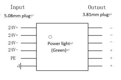
Figure 3-4-1
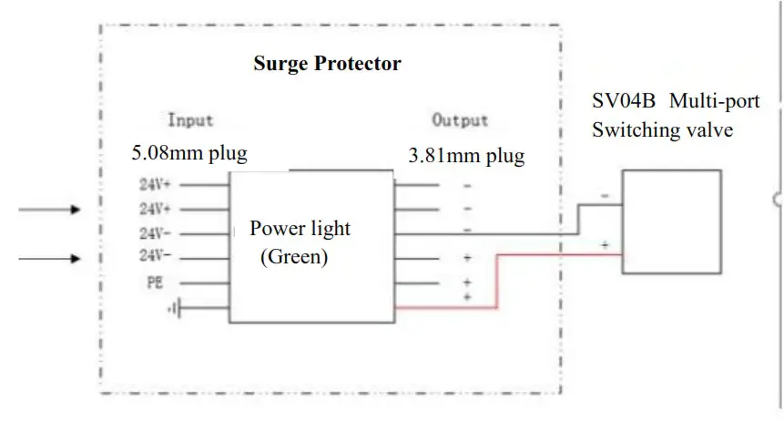
The Wiring Diagram of Surge Protector & SV04B
Chapter4 Common Problems & Solutions
| Phenomenon | Possible problem | Solution |
| Not working when powered on | Working voltage is not within the specified range | Check whether the voltage is within the specified range |
| The power connection is loose or disconnected | Check the power connection | |
| Working current is not within the specified range | Check whether the current is within the specified range | |
| Not aspirating after switching | The channel is blocked by particles | Take out the pump tube and check for blocked particles |
| Liquid has bubbles | The connector interface is not tight | Replace suitable connector |
| No communication | The TX and RX lines of RS232 are connected reversely or RS485 phase A & phase B are connected reversely | Exchange the TX and RX line sequence of RS232, exchange the A B phase sequence of RS485 |
| The communications sent and received are consistent in RS232 | TX & RX are in short circuit | Check if there is a short circuit, if yes, replace the cable |
Application Notice:
- Please ensure that the voltage matches the standard voltage of the instrument.
- Please use original serial port wires
- Communication RS232, RS485, CAN are under Non-isolation mode, hot swapping unsupported.
- Please cover the unused ports with suitable coned plugs when laid aside to avoid impurity substance and air
- Do not disassemble the product parts at will. The tamper-evident label is not guaranteed.
- Please read above operation instructions and communication protocols carefully, do not input data randomly.
- Discard the instrument should be in line with the regulations on the disposal. Dispose of the waste in accordance with national environmental protection requirements. Users should not throw away at will.
- When using CAN bus protocols to connect multiple devices, please refer to the connection method shown in Figure 4-1 below.
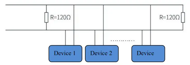 Figure 4-1
- When using RS485 protocol to connect multiple devices, please refer to the connection method shown in Figure 4-2 below (CAN resistance is removed)

Figure 4-2
![]()
Tel : +86-25-51197362 Fax : +86-25-51197362
Phone : +86-138 5195 4068
Technical support : +86-183 5195 5944, +86-198 2581 4316
Official URL : http://www.runzeflulid.com
Alibaba Store URL : https://runzeliuti.en.alibaba.com
Sales Email : [email protected]
Address : NO.9 Tianxing West Road, Dongshan Street, Jiangning District,
Nanjing, Jiangsu, China
 |  |