BUSHRANGER Night Hawk 7 Inch VLI Series LED Driving Light Owner’s Manual
Overview
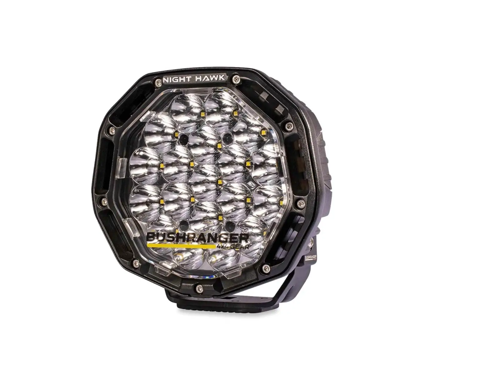
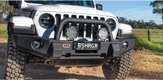
The Night Hawk Variable Series LED Driving Lights by Bushranger 4X4 have been developed from the ground up by our team of engineers to offer a truly unique design that takes performance, aesthetics and usability to a whole new level. They lead the way with simple, plug and play installation and an advanced control system that offers greater control and reliability over traditional on/off relay-based lighting systems.
The three variations offered in the Variable Series line-up unlock more options to suit the driver’s individual needs when tackling their next adventure. We have put user controlled lighting at the forefront of our development, and the ability to choose the optimum settings to suit an individual’s visual preference or the environment, plus change on the fly, sets these lights apart from the rest. This is high performance lighting that is adaptable to suit you and your needs.
Control the night.
Model Specific Features
Variable Beam Pattern | NXH230VBP
- 36 genuine high performance CREE LED’s.
- Electronically controlled Beam Pattern and Light Intensity settings.
- 8 Beam settings, from full spot to full flood.
- 8 Light Intensity settings, from 0% to 100%.
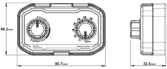
- Beam and Intensity settings are controlled with a backlit dual dial controller.
- Supplied with optional protective covers.
VCT Variable Colour Temperature | NHX230VCT
- 36 genuine high performance CREE LED’s.
- Electronically controlled Colour Temperature and Light Intensity settings.
- 8 Colour settings, from warm white to day white (3000K – 6000K).
- 8 Light Intensity settings, from 0% to 100%
- Colour and Intensity settings controlled with a backlit dual dial controller.
- Supplied with optional spot and flood protective covers.
VLI Variable Light Intensity | NHX230VLI – NHX180VLI
- Available in both 7” and 9” sizes.
- 37 (9”) or 19 (7”) genuine high performance OSRAM LED’s.
- Electronically controlled Light Intensity settings.
- 8 Light Intensity settings from 0% to 100%.
- Intensity settings controlled with a single dial controller.
- Supplied with optional spot and flood protective covers.
Variable Series Driving Light Features
- Versatile Installation
- Unique shape and low profile design allows for diverse fitments where regular round lights may not suit.
Superior Cooling Design
- Large air intakes channel cool air over the heat sink for unmatched cooling Active Temperature Control System
- Intelligent onboard monitoring of the LED temperatures, combined with the superior cooling design allows for maximum output in all conditions. High Performance Genuine LED’s
- Genuine high output CREE or OSRAM LED’s for unmatched performance
- Tested by an Australian NATA accredited photometry lab to produce real light performance data
Modern Electronics Design
- Built in Transistor switching simplifies wiring installation by removing the need for traditional 12V relay switching.
- PWM output provides complete control at the turn of the dial.
- Over voltage and Reverse Polarity Protection.
Durable Exterior
- Hard Coated polycarbonate lens offers long term scratch resistance ensuring maximum optical efficiency for years to come.
- UV stable Akko Nobel Powder coat, polycarbonate lens and protective covers ensure long term durability in the harsh Australian environment.
Built Tough
- Pressure die-cast aluminum housing and strong, 4mm thick stainless steel brackets will handle even the toughest tracks.
- Designed, engineered and extensively tested in Australia.
- Vibration tested to SAE J575 – Shock/Vibration Standards
Sealed Tight
- Waterproof and submersible, IP67 & IP69K rated.
- Genuine GORE breather manages the internal air pressure of the light, preventing water ingress in all conditions.
Specifications
Variable Beam Pattern
Single Light Specification
| Power | 170W |
| Current Draw | 11.9A @14.4V |
| Voltage Range | 10-30V DC |
| Luminous Flux | 10,800 (effective) without protective covers fitted |
| LED Type | 36 x Genuine CREE LED’s |
| LED Colour Temperature | 5700k (72 CRI) |
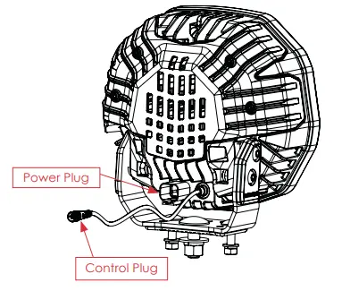
| Power Plug | Deutsch DTP |
| Control Plu | 4 pin round |
| Fitted Weight | 3.2kg |
| Compliance | CE, UNECE R10, IP67 & IP69K, RoHS, SAE J575 – Shock/ Vibration |
VBP WIRING SYSTEM SPECIFICATIONS
| Voltage Range | 10 – 30V DC |
| Controller | Backlit with two rotary control dials & mounting cradle |
| Light Intensity Control | 8 x Brightness settings (0% – 100%) |
| Beam Pattern Control | 8 x Beam pattern settings (Spot – Flood) |
| Light Capacity (as supplied) | Connect and control 2 x VBP Series lights simultaneously |
| Light Capacity (max) | Connect and control 4 x VBP Series lights simultaneously (additional lights and control leads sold separately) |
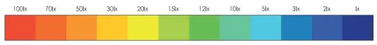
Isolux Data (Pair of Lights)
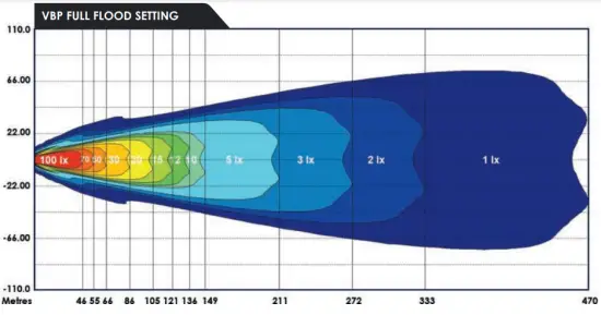
All results shown below are obtained from real scientific testing carried out by a NATA Accredited Photometric Laboratory in Australia. Measurements displayed with optional clear protective covers fitted.
VBP FULL FLOOD SETTING
VBP COMBO SETTING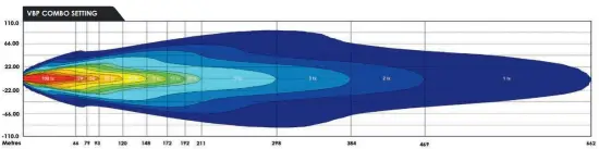
VBP FULL SPOT SETTING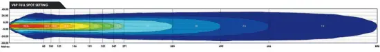
Light Performance (Pair of Lights)
| Beam Pattern | Full Spot | Combo (Setting 4) | Flood Covers |
| Max distance @ 1 lux | 857m | 661m | 469m |
| Max width @ 1 lux | 68m | 117m | 164m |
OPTIONAL PROTECTIVE COVERS REMOVED
| Beam Pattern | Full Spot | Combo (Setting 4) | Flood Covers |
| Max distance @ 1 lux | 939m | 724m | 512m |
| Max width @ 1 lux | 75m | 128m | 164m |
Variable Color Temperature
SINGLE LIGHT SPECIFICATIONS
| Power | 170W |
| Current Draw | 11.9A @14.4V |
| Voltage Range | 10-30V DC |
| Luminous Flux | 10,400 (effective) without protective covers fitted |
| LED Type | 36 x Genuine CREE LED’s |
| LED Colour Temperature | 3000K (82 CRI) & 6000K (72 CRI) |
| Power Plug | Deutsch DTP |
| Control Plu | 4 pin round |
| Fitted Weight | 3.2kg |
| Compliance | CE, UNECE R10, IP67 & IP69K, RoHS, SAE J575 – Shock/ Vibration |
VCT WIRING SYSTEM SPECIFICATIONS
| Voltage Range | 10 – 30V DC |
| Controller | Backlit with two rotary control dials & mounting cradle |
| Light Intensity Control | 8 x Brightness settings (0% – 100%) |
| Beam Pattern Control | 8 x colour temperature settings (3000K – 6000K) |
| Light Capacity (as supplied) | Connect and control 2 x VBP Series lights simultaneously |
| Light Capacity (max) | Connect and control 4 x VBP Series lights simultaneously (additional lights and control leads sold separately) |
Isolux Data (Pair of Lights)
All results shown below are obtained from real scientific testing carried out by a NATA Accredited Photometric Laboratory in Australia. Measurements displayed with optional clear protective covers fitted.
VCT WITH FLOOD COVERS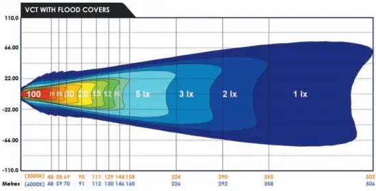
VCT WITH 1X SPOT & 1X FLOOD COVER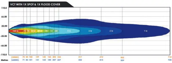
VCT WITH SPOT COVERS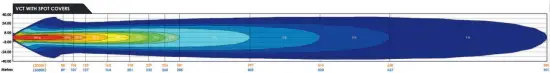
6000K TEMPERATURE SETTING
| Optional Protective Covers | Covers Removed | Spot Covers | Flood Covers | 1 Flood Cover 1 Spot Cover |
| Max distance @ 1 lux | 974m | 900m | 506m | 719m |
| Max width @ 1 lux | 80m | 74m | 150m | 113m |
3000K TEMPERATURE SETTING
| Optional Protective Covers | Covers Removed | Spot Covers | Flood Covers | 1 Flood Cover 1 Spot Cover |
| Max distance @ 1 lux | 960m | 888m | 501m | 709m |
| Max width @ 1 lux | 78m | 72m | 149m | 112m |
Variable Light Intensity
SINGLE LIGHT SPECIFICATIONS
| Power | 170W |
| Current Draw | 11.9A @14.4V |
| Voltage Range | 10-30V DC |
| Luminous Flux | 10,700 (effective) without protective covers fitted |
| LED Type | 37 x Genuine CREE LED’s |
| LED Colour Temperature | 5700K (72 CRI) |
| Power Plug | Deutsch DTP |
| Control Plu | 4 pin round |
| Fitted Weight | 3.2kg |
| Compliance | CE, UNECE R10, IP67 & IP69K, RoHS, SAE J575 – Shock/ Vibration |
VLI WIRING SYSTEM SPECIFICATIONS
| Voltage Range | 10 – 30V DC |
| Controller | Backlit with two rotary control dials & mounting cradle |
| Light Intensity Control | 8 x Brightness settings (0% – 100%) |
| Light Capacity (as supplied) | Connect and control 2 x VLI Series lights simultaneously |
| Light Capacity (max) | Connect and control 4 x VBP Series lights simultaneously (additional lights and control leads sold separately) |
Isolux Data (Pair of Lights)
All results shown below are obtained from real scientific testing carried out by a NATA Accredited Photometric Laboratory in Australia. Measurements displayed with optional clear protective covers fitted.
VLI 9” WITH FLOOD COVERS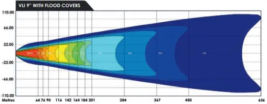
VLI 9” WITH 1X SPOT & 1X FLOOD COVER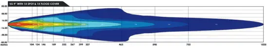
VLI 9” WITH SPOT COVERS
Light Performance (Pair of Lights)
HIGHEST INTENSITY SETTING
| Optional Protective Covers | Covers Removed | Spot Covers | Flood Covers | 1 Flood Cover + 1 Spot Cover |
| Max distance @ 1 lux | 1486m | 1362m | 636m | 1035m |
| Max width @ 1 lux | 86m | 86m | 200m | 147m |
Variable Light Intensity
SINGLE LIGHT SPECIFICATIONS
| Power | 85W |
| Current Draw | 5.9A @14.4V |
| Voltage Range | 10-30V DC |
| Luminous Flux | 6,450 (effective) with protective covers fitted |
| LED Type | 19 x Genuine OSRAM LED’s |
| LED Colour Temperature | 5700K (72 CRI) |
| Power Plug | Deutsch DTP |
| Control Plug | 4 pin round |
| Fitted Weight | 1.7kg |
| Compliance | CE, UNECE R10, IP67 & IP69K, RoHS, SAE J575 – Shock/ Vibration |
VLI WIRING SYSTEM SPECIFICATION
| Voltage Range | 10 – 30V DC |
| Controller | Single rotary control dial & mounting cradle |
| Light Intensity Control | 8 x Brightness settings (0% – 100%) |
| Light Capacity (as supplied) | Connect and control 2 x VLI Series lights simultaneously |
| Light Capacity (max) | Connect and control 4 x VBP Series lights simultaneously (additional lights and control leads sold separately) |
Isolux Data (Pair of Lights)
All results shown below are obtained from real scientific testing carried out by a NATA Accredited Photometric Laboratory in Australia. Measurements displayed with optional clear protective covers fitted.
VLI 7” WITH FLOOD COVERS

VLI 7” WITH 1X SPOT & 1X FLOOD COVER
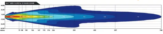
VLI 7” WITH SPOT COVERS
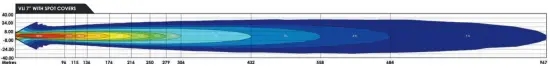
Light Performance (Pair of Lights)
HIGHEST INTENSITY SETTING
| Optional Protective Covers | Covers Removed | Spot Covers | Flood Covers | 1 Flood Cover + 1 Spot Cover |
| Max distance @ 1 lux | 1486m | 1362m | 636m | 1035m |
| Max width @ 1 lux | 86m | 86m | 200m | 147m |
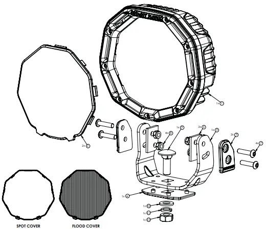
COMPONENTS
Components Diagram – NHX230 9” Single Light
| Item# | Component Name | Qty |
| 1 | NHX230 Driving Light | 1 |
| 2 | Cover (1 x Spot, 1 x Flood)* | 2 |
| 3 | Mounting Bracket | 1 |
| 4 | Side Plate (1 x Left, 1 x Right) | 2 |
| 5 | Side Rubber Isolator | 2 |
| 6 | Bottom Rubber Isolator | 1 |
| 7 | M8 x 30mm Cup Head Bolt | 2 |
| 8 | M8 Flat Washer | 2 |
| 9 | M8 Spring Washer | 2 |
| 10 | M8 Nut | 2 |
| 11 | M8 x 30mm Button Head Bolt | 4 |
| 12 | M8 Nyloc Nut | 4 |
| 13 | M12 x 35mm Cup Head Bolt | 1 |
| 14 | M12 Flat Washer | 1 |
| 15 | M12 Spring Washer | 1 |
| 16 | M12 Nut | 1 |
| 17 | Power Lead 2.5m with 20A fuse (not shown) | 1 |
| 18 | Anti-Seize Lubricant Sachet (not shown) | 1 |
| 19 | Dielectric Grease Sachet (not shown) | 1 |
VBP driving light supplied with 1x Spot Cover per light.
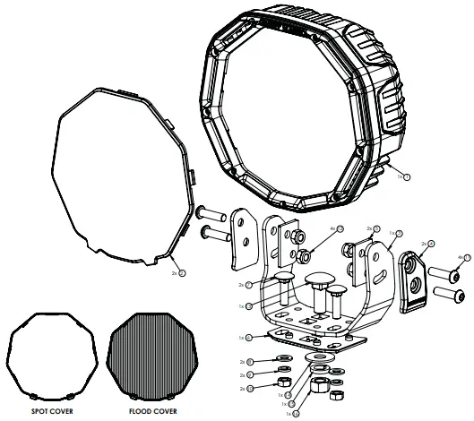
Components Diagram – NHX180 7” Single Light
| Item# | Component Name | Qty |
| 1 | NHX180 Driving Light | 1 |
| 2 | Cover (1 x Spot, 1 x Flood) | 2 |
| 3 | Mounting Bracket | 1 |
| 4 | Bottom Rubber Isolator | 1 |
| 5 | Side Plate (1 x Left, 1 x Right) | 2 |
| 6 | Side Rubber Isolator | 2 |
| 7 | M6 x 25mm Button Head Bolt | 4 |
| 8 | M6 Nyloc Nut | 4 |
| 9 | M10 x 30mm Cup Head Bolt | 1 |
| 10 | M10 Flat Washer | 1 |
| 11 | M10 Spring Washer | 1 |
| 12 | M10 Nut | 1 |
| 13 | Power Lead 2.5m with fuse (Not Shown) | 1 |
| 14 | Anti-Seize Lubricant Sachet (not shown) | 1 |
| 15 | Dielectric Grease Sachet (not shown) | 1 |
INSTALLATION
IMPORTANT!
- We recommend the lights/wiring to be fitted by a qualified automotive electrician.
- A forward facing light system may be used only as an auxiliary to high beam. Check compliance and regulations with local authorities.
- Vehicle accessories mounted on the outside of the vehicle may need to comply with regulations governed by your local state authority. Please check before installation.
- When mounting lights, position them appropriately so they do not obstruct existing automotive function. If fitting to front of vehicle, check for bonnet clearances.
- Consideration should be given for airflow requirements of the vehicle and its mechanical components when mounting lights.
- All stainless steel hardware must have anti-seize lubricant applied to the threads before tightening to avoid binding or galling of components.
- Ensure all recyclable parts/packaging are discarded in accordance to local regulations.
Light Mounting Bracket
The mounting bracket is supplied loosely fitted to the light. The stainless steel M6 x 25mm or M8 x 30mm button head bolts that secure the mounting bracket to the light must be removed and have anti-seize lubricant applied to the threads before final installation.
The use of anti-seize greatly reduces the risk of thread galling or binding commonly seen between stainless steel nuts and bolts during tightening. Anti-seize must also be applied to all the mounting fasteners used to secure the light to the vehicle.
Vehicle Mounting & Adjustment
Ensure the mounting location for fitment of the light/s to the vehicle is flat, stable, sufficiently strong and has enough clearance around the light to avoid damage to the vehicle from any movement during installation and use. If drilling is required for mounting, ensure raw edges are coated with corrosion resistant paint or inhibitor.
The light can be adjusted horizontally and vertically. All adjustments are to be made before final tightening of fasteners. Horizontal adjustment is gained by rotating the light body to the desired position and tightening the centre M10 or M12 bolt. Vertical adjustment is gained by tilting the light body up or down and tightening the 4 x side bolts.
The 9” light should always be secured to the vehicle using 1 x M12 center bolt and 2 x M8 side bolts as supplied. Apply anti-seize lubricant to these fasteners when fitting to the vehicle. For initial setup and adjustment, the fasteners should be finger tightened. Once all adjustments have been made, all fasteners should be tightened and torqued to the following specification:
RECOMMENDED TORQUE SETTINGS
| M8 Fasteners | 17Nm |
| M10 Fasteners | 33Nm |
| M12 Fasteners | 57Nm |
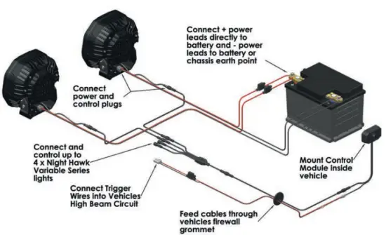
Wiring Installation
Please refer to the wiring system owners manual, for the full guide on driving light installation.
Care & Maintenance
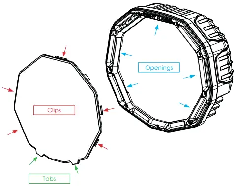
Cover Installation & Removal
Each single driving light comes with 2* protective covers, 1x clear spot beam cover and 1x fluted flood beam cover. (*except for the VBP model which comes with 1x clear spot cover).
To fit a protective cover, align the 5 x clips on the cover with the openings in the front of the light, then push cover firmly until all of the clips ‘click’ into the openings. To remove the cover, pull out on the 2 x lower tabs until the clips release from the light.
Light Care and Maintenance
- The light is not serviceable – DO NOT disassemble.
- Clean lights using pH neutral soapy water and a soft nonabrasive brush or sponge. Rinse thoroughly after cleaning.
- DO NOT use solvents, Alkaline based cleaners or abrasive materials to clean the light.
- If lights are exposed to a high salt environment or any other corrosive substance, remove the light and mounting bracket from the vehicle and thoroughly clean and rinse the components as outlined above.
- Remove the clear cover and plastic cover on the rear of the light periodically to clean any dirt and grime build up.
- Regularly check all fasteners to ensure they are secured and properly torqued.
Warranty Policy
- Our Warranty
We warrant to you that the Kingsley product is free from defects in workmanship and materials for the warranty period. - Fitting and use
Please ensure you:- fit the Kingsley product in accordance with the product information and all relevant vehicle safety and compliance laws
- use the Kingsley product for the purpose for which it was originally designed and in accordance with the product information and all relevant vehicle safety and compliance laws
- Exclusions
our warranty doesn’t cover:- normal wear and tear
- fitting the Kingsley product other than in accordance with the product information and any relevant vehicle safety and compliance laws, including incorrect fitting
- using the Kingsley product other than for the purpose for which it was originally designed or other than in accordance with the product information and any relevant vehicle safety and compliance laws, including unusual, improper or negligent use or misuse or overloading
- misuse or neglect of the Kingsley product, including improper repair or maintenance or failing to repair or maintain e. alteration, abuse, acts of nature, terrorism, vandalism, collision, road hazards or adverse conditions
- Making a claim
Please immediately contact us as soon as you become aware of a possible defect in the Kingsley product. We’ll arrange for you to either attend a Kingsley outlet (at your cost) for a Kingsley representative to inspect the Kingsley product (as fitted to your vehicle) or for you to return the Kingsley product to us. We’ll also request you to provide the purchase receipt and complete a warranty claim form. In order to ensure our warranty is not voided, please keep the purchase receipt as proof of purchase and don’t remove the fitted Kingsley product from your vehicle before contacting us. Note: Non-transferable warranty. The original purchaser can only claim warranty. If your claim’s in order, we’ll notify you and (at our sole discretion) either repair or replace the defective workmanship or materials (at our cost) or refund to you the purchase price you paid for the defective Kingsley product. If further information or investigation is required or if the claim does not meet the requirements under our warranty, we’ll let you know. - Australian Consumer Law
The Kingsley product comes with guarantees that can’t be excluded under the Australian Customer Law. You’re entitled to a replacement or refund if there’s a major failure and compensation for any other reasonably foreseeable loss or damage. You’re also entitled to have the Kingsley product repaired or replaced if it fails to be of acceptable quality and the failure doesn’t amount to a major failure. - Other consumer rights
The benefits to you under our warranty are in addition to any other rights and remedies you are entitled to under relevant consumer laws. Our warranty replaces any other warranty given by Kingsley or it’s supplier in respect of the Kingsley product. - Terms
The following terms have the following meanings:
| Term | Meaning |
| Product information | information about the Kingsley product which may be contained in any of the documentation provided with the Kingsley product, including safety instructions, installation instructions, operating instructions, owner’s manual, service manual, labels and packaging |
| Purchase date | the date you purchased the Kingsley product from a Kingsley outlet, as specified in the purchase receipt |
| Kingsley outlet | an outlet authorised by Kingsley to sell Kingsley products |
| Kingsley products | products or components which Kingsley manufacturers or sells through Kingsley outlets |
| Warranty period | commences on and from the purchase date and ends as follows: Night Hawk LED Driving Lights – 5 year warranty |
| We/Us | Kingsley Enterprises Pty Ltd (ABN 23 001 592 749) E: [email protected] A: 6A Brooks Road, Ingleburn NSW 2565 P: 1800 654 767 W: www.bushranger.com.au |
| You | the purchaser of the Kingsley product from a Kingsley outlet |
Kingsley Enterprises PTY. LTD.
Free Call: 1800 654 767 (Australia Only)
International: +61 2 8700 0400
Email: [email protected]
Address: 6A Brooks Road, Ingleburn NSW 2565


