![]() INSTALLATION INSTRUCTIONS
INSTALLATION INSTRUCTIONS
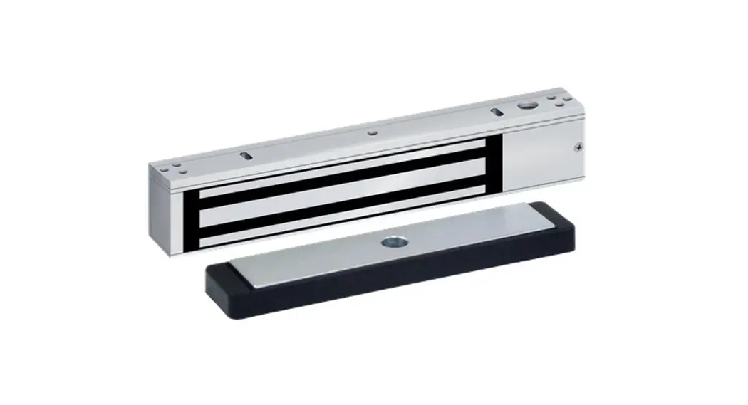
350
NARROW LINE EMLOCK
Retrofits Discontinued Locknetics 350+
Provides Superior Architectural Appearance
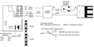
Electrical Instructions:
Use properly fused U. L. Listed Power Supply
Do not install a diode in parallel with any magnetic lock. A diode will cause a delay when releasing the door and residual magnetism to occur.
Access controls and/or release contacts must be located in series with the positive (+) power lead of the EmLock.
Any low voltage condition will cause erratic operation of the optional board sensor.
Although SDC recommends the use of a Regulated DC power supply.
A significant voltage drop will occur when using a full-wave bridge rectifier.
Installation Location – Indoor Dry use only PATENT NO. 5,376.910
Electrical Specifications:
| Dual Voltage | 12 or 24VDC |
| Power Consumption | 560mA@12VDC 309mA@24VDC |
| DS Door Status Sensor | SPDT, 250mA@24VDC |
| LS Lock Status Sensor | SPDT, 1A@24VDC Resistive |
Any suggestions or comments to this instruction or product are welcome. Please contact us through our website or email [email protected]
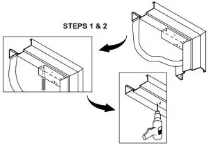
1. Fold template as indicated on the dotted line. For single doors locate the template against the door and header on the lock jamb side of the frame.2. Mark and drill holes as indicated by the template.
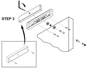
3. Mount armature to door.
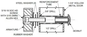 HOLLOW METAL DOOR
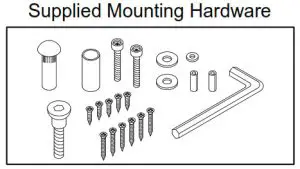
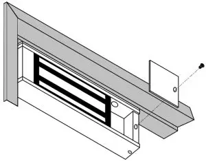
From the Sexnut side of the door, drill exactly 1/2″ hole thru one metal thickness only. From the Armature side of the door, drill 5/8″hole to insert reinforcement tube. Press in sex nut and reinforcement tube all the way and mount armature to door using hardware provided.4. Install magnet onto the header with the magnetic stripes towards the door side of the stop. Assure that the magnet and armature line up properly, then tighten down ALL mounting screws.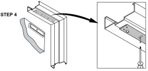
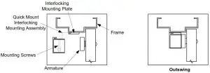
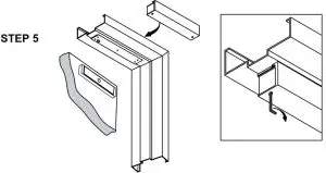
5. Holding the magnet housing at each end, engage the entire length of the interlock detail, by pushing towards the door. Tap with a soft hammer to ensure proper alignment and engagement.
CAUTION: The lock body must be held in place until secured with mounting screws. Secure socket head screws are provided inside the housing at each end. Start screws into threads carefully to avoid stripping the threads. Check alignment and tighten screws. Pull wires through the frame, mounting plate, and magnet housing
6. Select jumper position for 12VDC or 24VDC. Connect power to magnetic lock.
7. Test operation. When all is operating properly, tighten all screws.
To maintain surface plating from corrosion:
- Do not touch the lock face with your hands.
- Clean lock face with Scotch-Brite pad by 3M (do not use sandpaper).
- Apply a thin film of rust inhibitor (LPS-3) on the lock face.
- Repeat application on armature plate.
P:\INST INSTRUCTIONS\EMLOCKS\INST-350 REV A.4 09-21
SECURITY DOOR CONTROLS ■ WWW.SDCSECURITY.COM
[t] 800.413.8783 ■ 805.494.0622 ■ E-mail: [email protected] ■ 801 Avenida Acaso, Camarillo, CA 93012 ■ PO Box 3670, Camarillo, CA 93011


