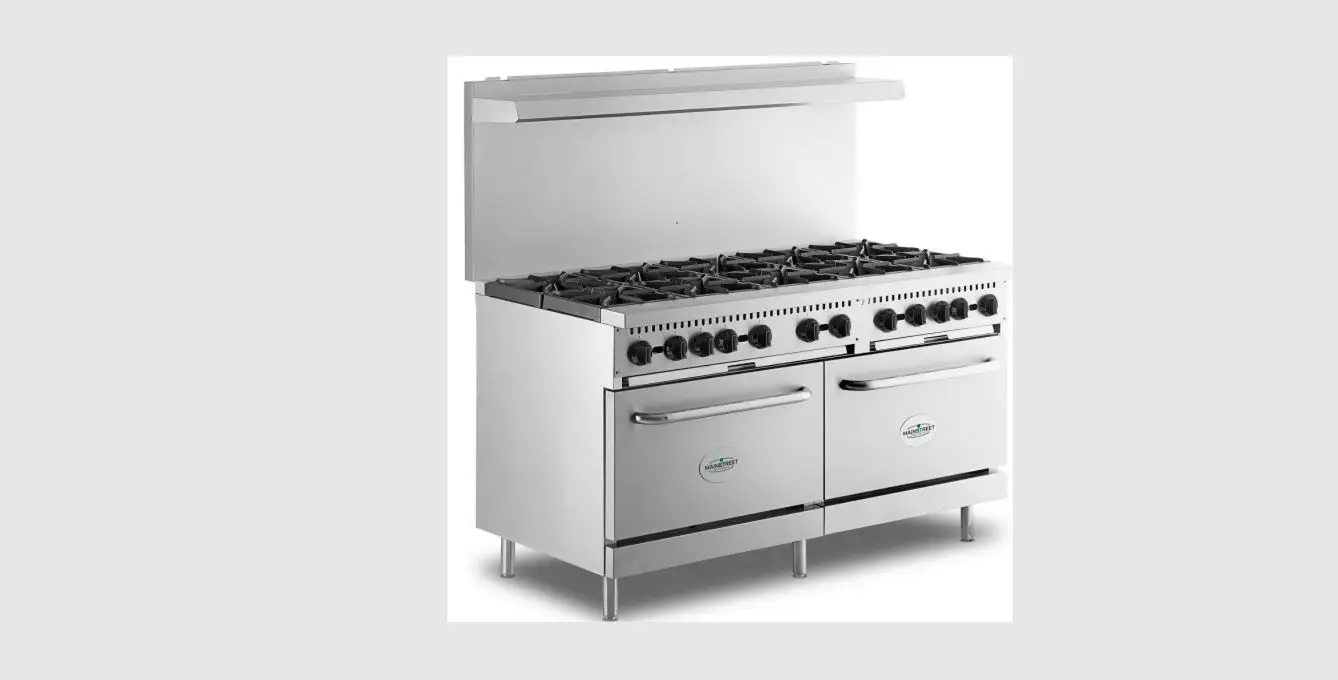
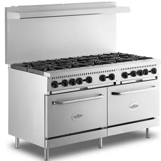
MAINSTREET EQUIPMENT 541E24L Liquid Propane 4 Burner 24 Inch Range
PRODUCT OVERVIEW
Main Street ranges feature independently controlled burners to improve kitchen efficiency and performance. The removable cast iron grates and pull-out crumb tray help to further expedite cleanup. Adjustable legs offer stability, while the handy kick plate ensures internal component protection and easy-access servicing. A convenient back shelf holds seasonings and supplies to maximize
efficiency. Featuring 24”, 36”, and 60” configurations, Main Street ranges are a versatile asset to busy commercial kitchens!
SAFETY PRECAUTIONS
CAUTION:
Failure to comply with the following operation instructions could lead to potential hazards and/or unsafe practice and could result in injury and damage to product and property
NOTICE:
Local codes regarding installation vary greatly from one area to another. The National Fire Protection Association, Inc., states in its NFPA96 latest edition that Local codes are “Authority Having Jurisdiction” when it comes to requirement for installation of equipment. Therefore, installation should comply with all Local codes.This product is intended for commercial use only. Not for residential use. Use in residential applications will void warranty.
WARNING:
Do not store or use gasoline or other flammable vapors and liquids in the vicinity of this or any other equipment.
Improper installation, adjustment, alteration, service or maintenance could lead to property damage, injury or death. Read the installation, operating and maintenance instructions thoroughly before installing or servicing Main Street equipment. This manual must be retained for future reference.
A factory authorized agent must handle all maintenance and repair
GAS PRESSURE
The appliance and its individual shutoff valve (to be supplied by user) must be disconnected from the gas supply piping system during any pressure testing of that system at test pressures in excess of 1/2 PSI (3.45 kPa) . The appliance must be isolated from the gas supply piping system by closing its individual manual shut-off valve during any pressure testing of the gas supply piping system at test pressures equal to or less than 1/2 PSI (3.45 kPa).
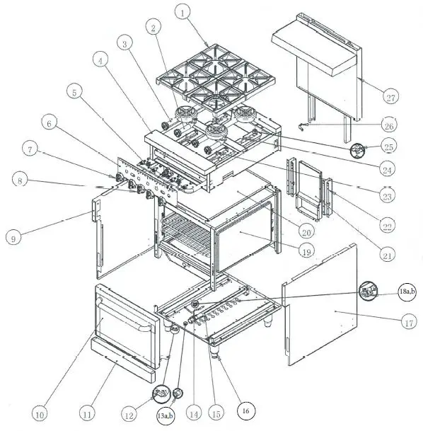
PARTS DIAGRAM 541E24(L/N)
| # | ITEM NUMBER | DESCRIPTION | QTY |
| 1 | 541302250132 | BURNER GRATE | 4 |
| 2 | 541128051028 | BURNER ASSEMBLY (SHORT) | 2 |
| 3 | 541128051027 | BURNER ASSEMBLY (LONG) | 2 |
| 4 | 54128058001 | FRAME ASSEMBLY | 1 |
| 5 | 54128058003 | GAS CONTROL ASSEMBLY | 1 |
| 6 | 54128058005 | FRONT CONTROL VALVE | 1 |
| 7 | 541202230111 | BURNER KNOB | 4 |
| BURNER KNOB CORE | 4 | ||
| 8 | 541301130111 | OVEN KNOB | 1 |
| OVEN KNOB CORE | 1 | ||
| 9 | 54128078022 | SIDE PANEL (LEFT) | 1 |
| 10 | 54128058006 | OVEN DOOR ASSEMBLY | 1 |
| 11 | 541228058021 | 24” KICK PLATE | 1 |
| 12 | 541302140137 | ORIFICE ELBOW | 1 |
| 13.a | 541302150198 | ORIFICE #36 – OVEN NAT | 1 |
| 13.b | 541302150189 | ORIFICE #50 – OVEN LP | 1 |
| 14 | 541302170058 | THERMOCOUPLE | 1 |
| 15 | 541302130384 | OVEN TANK ASSEMBLY | 1 |
| 16 | 541302090149 | ADJUSTABLE LEG | 4 |
| LEG MOUNTING PLATE | 4 | ||
| 17 | 54128078024 | SIDE PANEL (RIGHT) | 1 |
| 18.a | 541302130427 | PILOT OVEN NAT | 1 |
| 18.b | 541302130447 | PILOT OVEN LP | 1 |
| 19 | 54128058005 | OVEN TANK ASSEMBLY | 1 |
| 20 | 541228058007 | CRUMB TRAY 19” X 26” | 1 |
| 21 | 541128051007 | INNER FLUE ASSEMBLY | 1 |
| 22 | 541228051044 | SLIDE RAIL (REAR BAFFLE) | 2 |
| 23 | 541228046015 | GAS PIPE (PILOT) (SHORT BURNER) | 2 |
| 24 | 541228046016 | GAS PIPE (PILOT) (LONG BURNER) | 2 |
| 25 | 541302130019 | STOVE PILOT | 4 |
| 26 | 541302060231 | PIPE FIXER | 1 |
| 27 | 541128058007 | BACK PANEL ASSEMBLY | 1 |
| 28* | 541302140195 | BRASS FITTING (THERMOCOUPLE) | 1 |
| 29* | 541228080018 | THERMOCOUPLE PLATE | 1 |
| 30* | 541050081 | EXTERNAL REGULATOR | 1 |
| 31* | 541302090155 | CASTER W/BRAKE | OPTIONAL |
| 32* | 541302090156 | CASTER W/NO BRAKE | OPTIONAL |
| 33* | 541CASTER4 | CASTER SET OF 4 | OPTIONAL |
RANGE MAIN BODY
PARTS DIAGRAM 541E24(L/N)
| # | ITEM NUMBER | DESCRIPTION | QTY |
| 1 | 541302050051 | GAS STOVE VALVE | 4 |
| 2.a | 541302150198 | ORIFICE #36 – BURNER NAT | 4 |
| 2.b | 541302150190 | ORIFICE #51 – BURNER LP | 4 |
| 3 | 541200620 | SCREW | 1 |
| 4 | 541302220064 | GAS OVEN VALVE | 1 |
| 5 | 541302220027 | PILOT VALVE | 2 |
| 6 | 541302180496 | GAS INLET PIPE ASSEMBLY | 1 |
GAS CONTROL ASSEMBLY
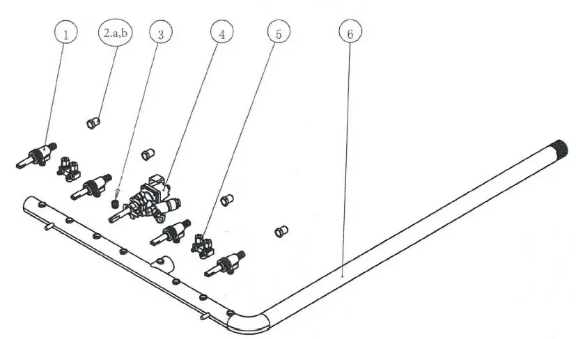
PARTS DIAGRAM 541E24(L/N)
| # | ITEM NUMBER | DESCRIPTION | QTY |
| 1 | 54128058014 | REAR SHROUDING ASSEMBLY | 1 |
| 2 | 54128058009 | OVEN TANK TOP PLATE | 1 |
| 3 | 54128051023 | SENSOR FIXED PLATE | 1 |
| 4 | 54128058010 | OVEN TANK LEFT PLATE | 1 |
| 5 | 54128051020 | OVEN TANK BOTTOM LEFT LIMIT PLATE | 1 |
| 6 | 54128058015 | OVEN TANK SIDE REINFORCE PLATE | 2 |
| 7 | 541302110504 | RACK HOLDER | 2 |
| 8 | 541302110557 | RACK 20” X 24.5” (OVEN CHAMBER) | 2 |
| 9 | 54128058013 | OVEN TANK LOWER FRONT PLATE | 1 |
| 10 | 54128058001 | BASEBOARD (CHAMBER) | 1 |
| 11 | 54128058017 | OVEN TANK BOTTOM REINFORCE PLATE | 1 |
| 12 | 541302190429 | DOOR HINGE – SEAT | 2 |
| 13 | 54128051021 | OVEN TANK BOTTOM LEFT RIGHT PLATE | 1 |
| 14 | 54128058011 | OVEN TANK RIGHT PLATE | 1 |
OVEN TANK ASSEMBLY
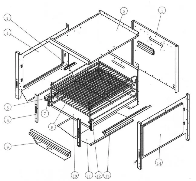
PARTS DIAGRAM 541E24(L/N)
| # | ITEM NUMBER | DESCRIPTION | QTY |
| 1 | 54128058023 | DOOR INNER PLATE | 1 |
| 2 | 541302190430 | DOOR HINGE – LEFT | 1 |
| 3 | 54128058025 | OVEN DOOR TOP REINFORCE | 1 |
| 4 | 54128051037 | OVEN DOOR LEFT REINFORCE | 1 |
| 5 | 54128058022 | DOOR OUTSIDE PANEL | 1 |
| 6 | 541302070220 | DOOR HANDLE | 1 |
| 7 | 54128058024 | OVEN DOOR BOTTOM REINFORCE | 1 |
| 8 | 54128051093 | OVEN DOOR RIGHT REINFORCE | 1 |
| 9 | 541302190428 | DOOR HINGE – RIGHT | 1 |
OVEN DOOR ASSEMBLY
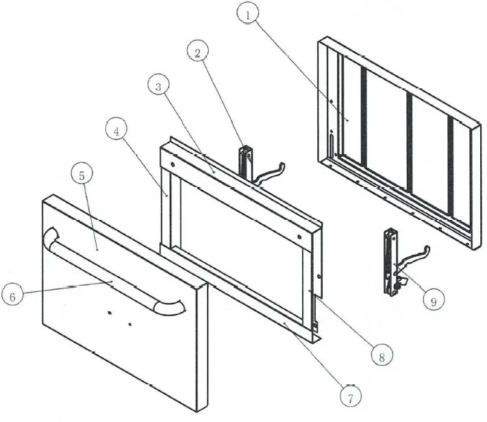
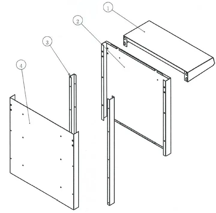
PARTS DIAGRAM 541E24(L/N)
| # | ITEM NUMBER | DESCRIPTION | QTY |
| 1 | 54128058028 | DECORATIVE COVER | 1 |
| 2 | 54128058026 | BACK FRONT PANEL | 1 |
| 3 | 54128051040 | BACK SUPPORT PANEL | 2 |
| 4 | 54128058027 | BACK REAR PANEL | 1 |
BACK PANEL ASSEMBLY