
Honeywell Home EWA1xxC-MBUS

Introduction
EWA1xxC-MBUS are a range of clip on modules for EW110 and EW171 Series water meters. Meters fitted with this module have two configurable pulse out-puts for remote readout. Per meter one module is required. The module is ret-rofittable at any time, also when the meter is in operation. When the module is in place no other module can be fitted as EW110 and EW171 Series only pro-vide space for one module. Other available modules are Pulse out (EWA1xxC-PO). However, this document only includes in-structions for configuration of the M-Bus module.
Scope
These instructions are valid for the following modules:
Table 1. OS-Numbers covered
| OS-Number | Item |
| EWA110C1520-MBUS | M-Bus clip-on module for EW110 Series, DN15 and DN20 |
| EWA110C2540-MBUS | M-Bus clip-on module for EW110 Series, DN25 to DN40 |
| EWA171C-MBUS | M-Bus clip-on module for EW171 Series, DN50 to DN300 |
Preparation
Programming of M-Bus clip on modules is done via the M-Bus master EW535M. It is not possible to program the module before it has been connected to the M-Bus. For programming the second-ary address of the module must be known. If the actual volume should be included in the programming this data must also be known.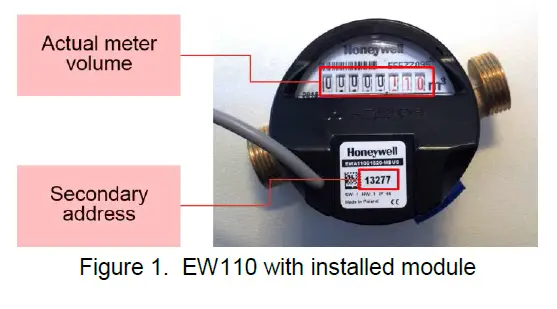 Standard Values
Before programming modules check if standard values are not sufficient and thus make programming needless:
Table 2. Standard values
| OS-No. | Baud rate | Volume | Backward flow | Min/max flow | Leakage | Primary address | Lack of flow |
| EWA110C1520-MBUS | 2,400 | 0 | deactivated | deactivated, JS1.6 | deactivated | 0 | deactivated |
| EWA110C2540-MBUS | 2,400 | 0 | deactivated | deactivated, JS6.3 | deactivated | 0 | deactivated |
| EWA171C-MBUS | 2,400 | 0 | deactivated | deactivated, MWN40 | deactivated | 0 | deactivated |
Required Parts
The following parts are required to change the programming of the module. The list is based on the assumption that programming will be done via an EW535M IzarCenter M-Bus master unit.
Table 3. Required parts
| Part | Function | |
| Serial cable (supplied with Izar- Center) | Interface between PC and module | |
| USB / serial adapter | Connect serial cable to PCs without serial interface | |
| Configuration software EWASET-MBUS | Program new values into module | Downloadable free of charge from https://homecomfort.resideo.com/sites/Europe/en-gb/Solu- tions/Metering/Pages/Metering.aspx |
Wiring to PC
Wiring between PC and module is done via the M-Bus master EW535M. Connection between PC and M-Bus mas-ter must be done over the serial port, not the USB port, of the IzarCenter.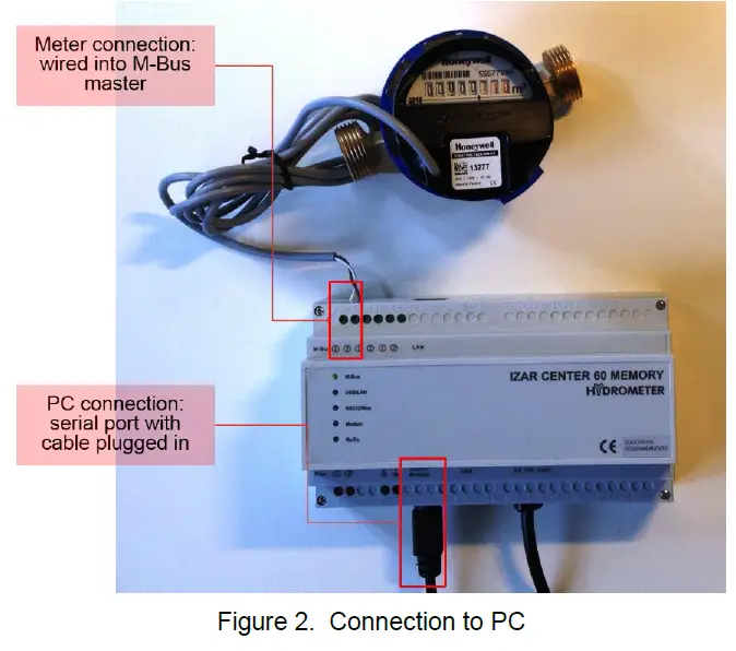
Programming
Wake up
NOTE: This chapter applies only to modules produced before August 2015. After production the module is put into sleep mode to save battery life. When installed on a meter the module is woken up automatically. For programming before installation briefly place a magnet near the reed switch of the module. By this the module is woken up from sleep mode.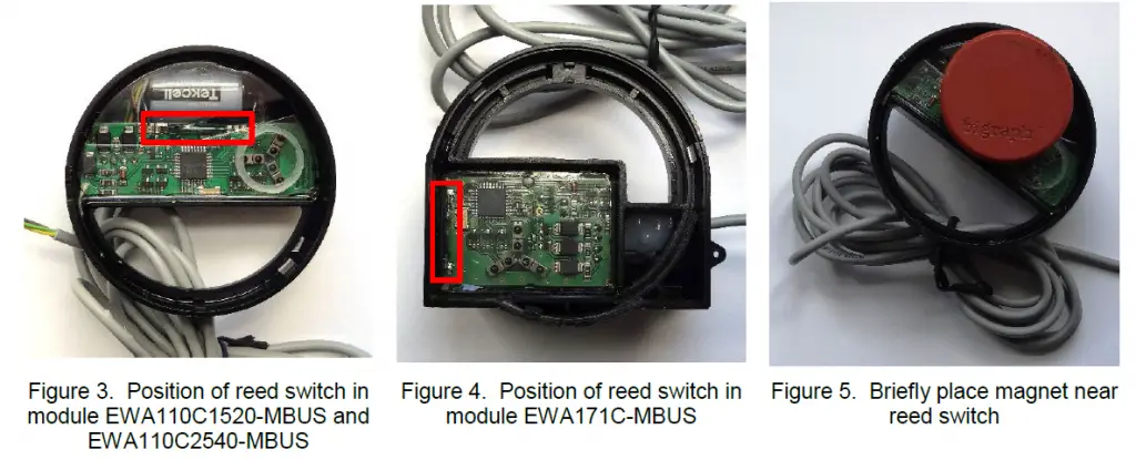 Software
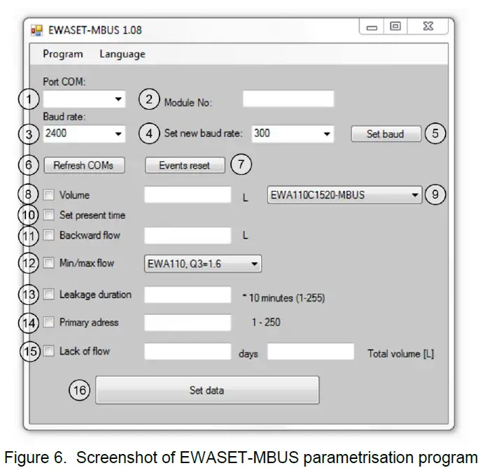
Fields
| Field No. | Field name | Field type | Function |
| 1 | Port COM | Pulldown | Select COM port over which the PC is con- nected to the M-Bus master. |
| 2 | Module No. | Input | Put in secondary address of module which should be programmed. |
| 3 | Baud rate | Pulldown | Select baud rate for communication. Standard baud rate is 2,400. |
| 4 | Set new baud rate | Pulldown | Select new baud rate if required and program with “Set baud” button. |
| 5 | Set baud | Execute button | |
| 6 | Refresh COMs | Execute button | |
| 7 | Events reset | Execute button | |
| 8 | Volume | Activation / input | Optionally put in meter volume count |
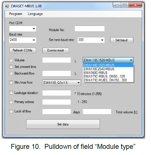
| 9 | Module type | Pulldown | Select module type to be addressed |
| 10 | Set present time | Activation | Optionally activate if PC time should be pro- grammed into module. |
| 11 | Backward flow | Activation / input | Optionally set backward flow threshold. |
| 12 | Min/Max flow | Activation / pulldown | Optionally set minimum and maximum flow rates by selecting type of meter attached. |
| 13 | Leakage duration | Activation / input | Optionally set a threshold after which a leak- age alarm is generated. |
| 14 | Primary address | Activation / input | Optionally set new primary address. |
| 15 | Lack of flow | Activation / 2 inputs | Optionally set a threshold for time and volume after which an alarm is generated in case no flow took place. |
| 16 | Set data button | Execute button | Program values into module. |
Field Description
Port COM
Required to select the correct COM port over which the PC is connected to the M-Bus master unit.
Module No.
The module number is the unique identification number of the module to be addressed. (It is also the secondary address of the module.) In this field the module number of the module to which the parametrisation data shall be sent is put in. The module number is printed on the label on the top of the module, see Figure 7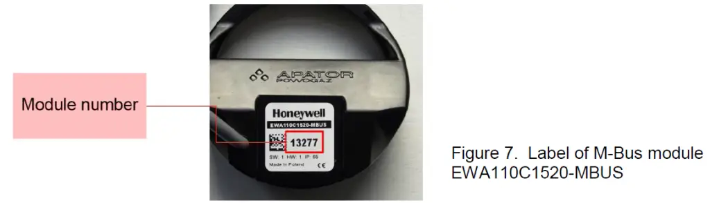
Baud rate
In this field the actual baud rate of the module is entered. Standard value is 2,400.
Set new baud rate
In this field a new baud rate can be entered if the standard baud rate should be changed. Baud rate can be set to 300 or 2,400 baud.
Set baud
Upon execution baud rate of module will be set to value selected in field 4. Successful baud rate change is con-firmed by a system message.
Refresh COMs
Upon execution the list of COM ports currently recognised by the program will be updated.
Events reset
Upon execution the error log of the module is erased. Fields 8 and 10…16 are optional configuration items. They can be individually activated by setting a tick in the box before the input field and entering a value.
Volume
In this field the actual meter count should be entered to ensure that the meter reading and the value reported over the M-Bus are identical.
When the M-Bus module is installed onto the water meter the reading of the meter is never 0.000: in case of a ret-rofit the meter is likely to have been in operation already. But also in case of a new meter the reading is not zero due to qualification testing which is undertaken on every meter before it is released for shipment. The information in this field ensures that the reading over the M-Bus is identical with the count shown on the meter face. In below example (Figure 8) the reading is 290.35 litres. The input value is “290” as the field is populated with full litres, no decimal places.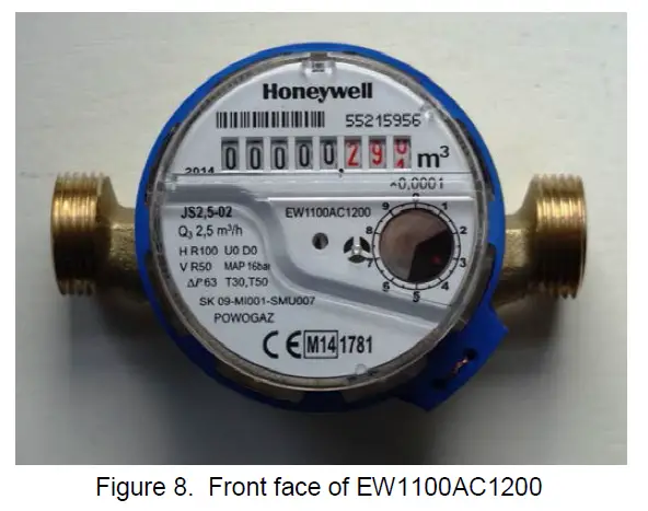
Module type
In this field the correct module must be selected by OS-Number. The OS-Number is printed on the label on the top of the module: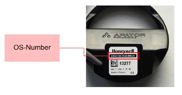
Set present time
When this field is active the computer time and date will be transmitted to the module and overwrite the value stored in the module.
Backward flow
When this field is activated a threshold for backward flow can be input in litres and an error message will be generated whenever this threshold is exceeded.
Min/Max flow
When this field is activated the type of meter can be selected in terms of flow. In this case an error message is generated whenever the flow values are outside of the approved meter range. The following values are available. OS-Number “EW110…0600” means all OS-Numbers starting with “EW110” and ending with “0600” are included.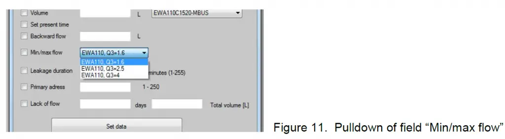
Table 5. Min/Max flow values
| Field value | For OS-Numbers | Min flow value | Max flow value |
| EWA110, Q3=1.6 | EW110…0600 | 10 litres / hour | 2 m³ / hour |
| EWA110, Q3=2.5 | EW110…1100 EW110…1200 EW110…1400 | 16 litres / hour | 3.125 m³ / hour |
| EWA110, Q3=4 | EW110…2000 | 25 litres / hour | 5 m³ / hour |
| EWA110, Q3=6.3 | EW110…2800 | 32 litres / hour | 7.9 m³ / hour |
| EWA110, Q3=10 | EW110…3900 | 50 litres / hour | 12.5 m³ / hour |
| EWA110, Q3=16 | EW110…4600 | 80 litres / hour | 20 m³ / hour |
| EWA171, Q3=25 | EW1711AC5000 | 0.25 m³ / hour | 31 m³ / hour |
| EWA171, Q3=40 | EW1710AC5000 EW1711AC5600 | 0.4 m³ / hour | 50 m³ / hour |
| EWA171, Q3=63 | EW1710AC5600 EW1711AC6500 | 0,5 m³ / hour | 78 m³ / hour |
| EWA171, Q3=100 | EW1710AC6500 EW1711AC7300 | 0.63 m³ / hour | 125 m³ / hour |
| EWA171, Q3=160 | EW1710AC7300 EW1711AC8100 | 0.8 m³ / hour | 200 m³ / hour |
| EWA171, Q3=250 | EW1710AC8100 EW1711AC8500 | 1.6 m³ / hour | 313 m³ / hour |
| EWA171, Q3=400 | EW1710AC8500 EW1711AC8900 | 2 m³ / hour | 500 m³ / hour |
| EWA171, Q3=630 | EW1710AC8900 EW1711AC9100 | 5 m³ / hour | 788 m³ / hour |
| EWA171, Q3=1 000 | EW1710AC9100 EW1711AC9200 | 10 m³ / hour | 1,250 m³ / hour |
| EWA171, Q3=1 600 | EW1710AC9200 | 16 m³ / hour | 2,000 m³ / hour |
NOTE:
- For EW110 Series min flow of version with dynamic range of R160 is used.
- For EW171 Series min and max flows of cold water meter are used.
Leakage duration
When this field is activated a threshold for leakage can be input in minutes where the threshold value is ten times the input value. Example: when “6” is input the threshold value will be “60 minutes” (6 x 10). An error message will be generated whenever this threshold is reached or exceeded, i.e. when there has been a continuous flow for sixty minutes or more.
Primary address
When this field is activated a new primary address can be set between 1 and 250. The module is supplied with primary address 0.
Lack of flow
When this field is activated a threshold for no flow can be input and an error message will be generated whenever this threshold is not reached in the given number of days. The threshold is defined in terms of days and total vol-ume. It means that whenever the defined volume is not reached within the number of days defined an error message is generated.
Set data
Upon execution parametrisation data will be written into the module. Successful transmission is confirmed by a system message.
Manufactured for and on behalf of Pittway Sarl, Z.A., La Pièce 4, 1180 Rolle, Switzerland
by its authorised representitive Ademco 1 GmbH
For more information
homecomfort.resideo.com/europe
Ademco 1 GmbH, Hardhofweg 40,
74821 MOSBACH, GERMANY
Phone: +49 6261 810
Fax: +49 6261 81039![]()


