![]()
Origins Trim Series
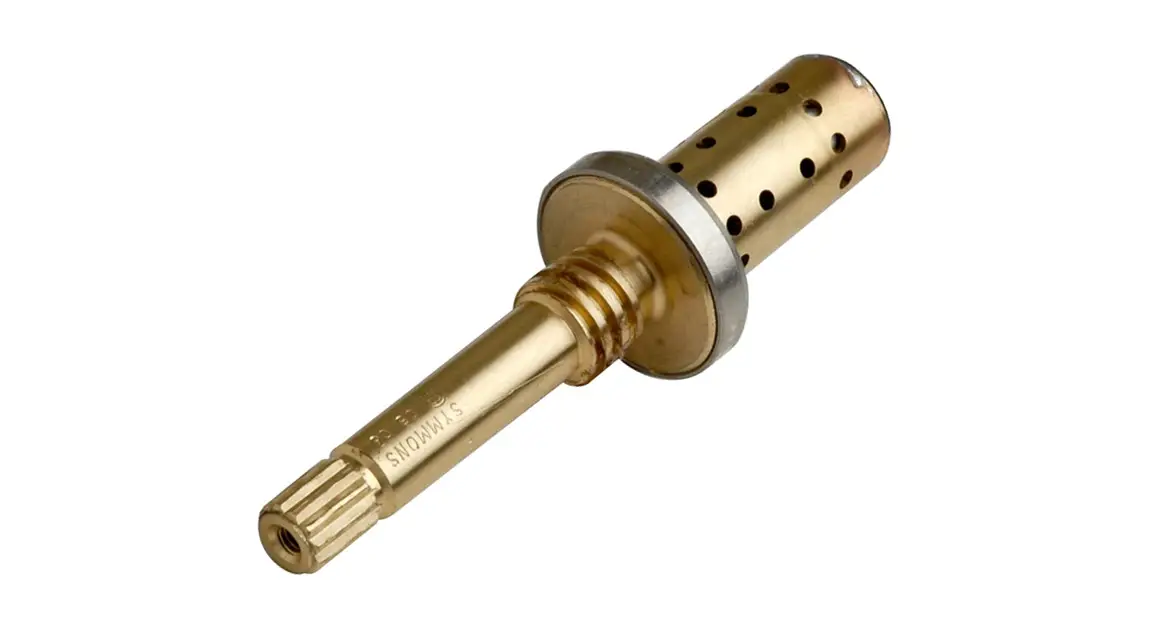
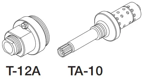
Origins Trim Series with TA-10 Flow Control Spindle & T-12A Cap Assembly
Installation & Operation Instructions
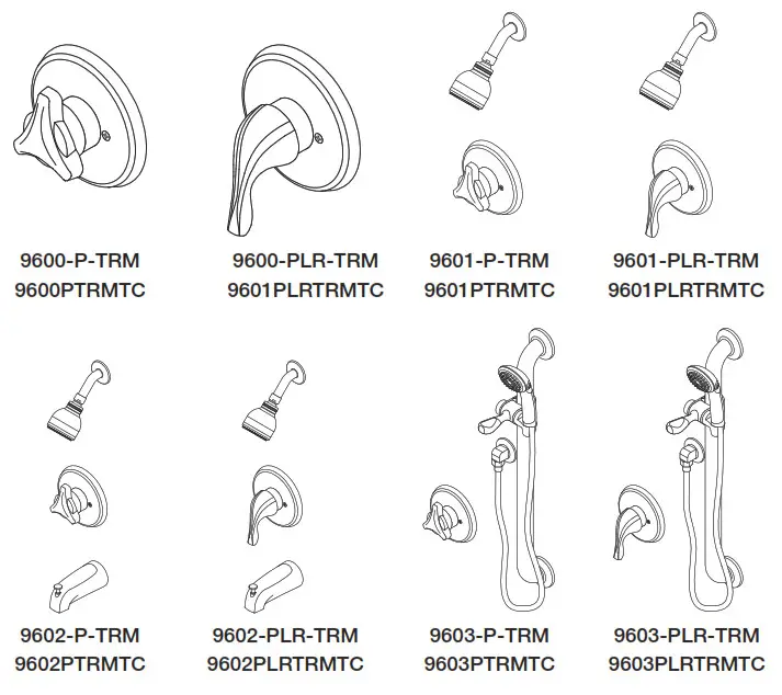
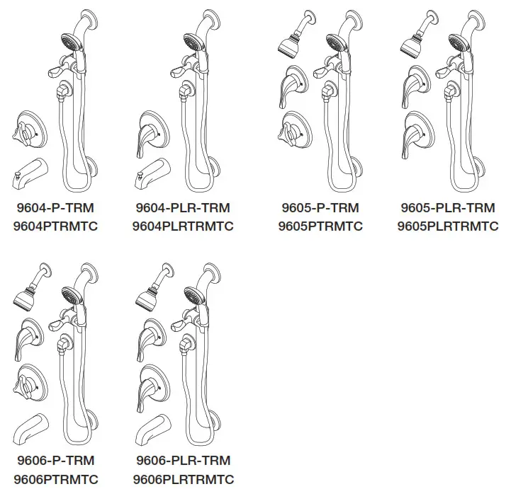
Model Numbers
| TRIM ONLY 9600-P-TRM Shower Valve Trim 9600-PLR-TRM Shower Valve Trim 9601-P-TRM Shower Trim 9601-PLR-TRM Shower Trim 9602-P-TRM Tub/Shower Trim 9602-PLR-TRM Tub/Shower Trim 9603-P-TRM Hand Shower Trim 9603-PLR-TRM Hand Shower Trim 9604-P-TRM Tub/Hand Shower Trim 9604-PLR-TRM Tub/Hand Shower Trim 9605-P-TRM Shower/Hand Shower Trim 9605-PLR-TRM Shower/Hand Shower Trim 9606-P-TRM Tub/Shower/Hand Shower Trim 9606-PLR-TRM Tub/Shower/Hand Shower Trim | TRIM, TA-10, T-12A 9600PTRMTC Shower Valve Trim 9600PLRTRMTC Shower Valve Trim 9601PTRMTC Shower Trim 9601PLRTRMTC Shower Trim 9602PTRMTC Tub/Shower Trim 9602PLRTRMTC Tub/Shower Trim 9603PTRMTC Hand Shower Trim 9603PLRTRMTC Hand Shower Trim 9604PTRMTC Tub/Hand Shower Trim 9604PLRTRMTC Tub/Hand Shower Trim 9605PTRMTC Shower/Hand Shower Trim 9605PLRTRMTC Shower/Hand Shower Trim 9606PTRMTC Tub/Shower/Hand Shower Trim 9606PLRTRMTC Tub/Shower/Hand Shower Trim |
 Compliance

- ASME A112.18.1/CSA B125.1
Warranty
Limited Lifetime – to the original end purchaser in consumer/residential installations.
5 Years – for industrial/commercial installations.
Refer to www.symmons.com/warranty for complete warranty information.
Go to www.symmons.com/register to register your Symmons product.
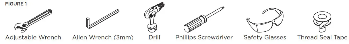
Recommended Tools
Dimensions
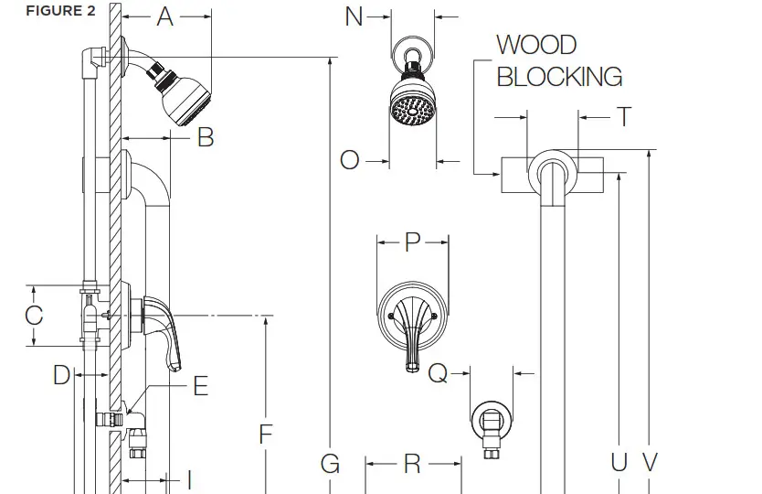
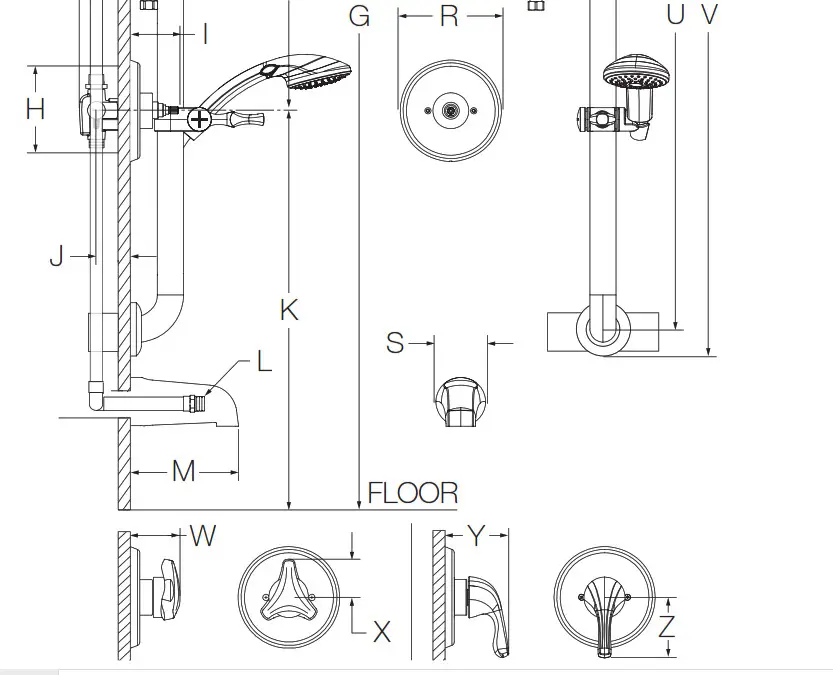
Measurements | |
| A | 6-3/8″. 162 mm |
| B | 3″. 76 mm |
| C | Diverter Valve Hole Size Min. 0 3″. 76 mm Max. 0 3-1/4″. 83 mm |
| D | 3 1/2″. 89 mm |
| E | Male 1/2″ NPT fitting must protrude 3/8″ from the finished wall |
| F | Ref. 10″. 254 mm |
| G | Ref. 77″. 1956 mm |
| H | Shower Valve Hole Size Min. 0 3″. 76 mm Max. 0 4″. 102 mm |
| I | 2-7/8″. 73 mm |
| Rough-in 2-3/8″ ± V2″. 60 mm ± 13 mm | |
| K | 9600, 9601, 9603, 9605: Ref. 42″. 1067 mm 9602, 9604, 9606: Ref. 32″. 813 mm |
| L | Male 1/2″ NPT fitting must protrude 4″ from the finished wall |
| M | 5-1/2″. 140 mm |
| N | 0 2-1/2″. 64 mm |
| 0 | 0 2-3/4″. 70 mm |
| P | 0 4-1/4″. 108 mm |
| 0 | 0 2-1/2″. 64 mm |
| R | 0 5-3/4″. 146 mm |
| S | 0 2-1/2″. 64 mm |
| T | 0 3-1/8″. 79 mm |
| U | 36″. 914 mm |
| V | 39″. 991 mm |
| W | 2-7/8″. 73 mm |
| X | 2-1/8″. 54 mm |
| Y | 3-5/8″. 92 mm |
| Z | 3-3/8″. 86 mm |
Notes:
- Valve body and piping not included and shown as reference only.
- Plaster shield (p/n T-176) for drywall, plaster or other type walls 1/2″ or greater.
- All dimensions measured from nominal rough-in (see J as reference).
- Dimensions subject to change without notice.
Parts Breakdown (Model Numbers Ending in TRMTC)
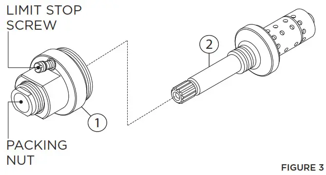
| Item | Description | Part Number |
| 1 | Cap Assy. | T-12A |
| 2 | Flow Control Spindle | TA-10 |
IMPORTANT: Model numbers ending in TRMTC coordinate with Temptrol pressure-balancing valves ordered with Test Cap. The Test Cap is used to allow pressurization of the system. Do not remove test cap from the valve during wall construction, installation of valve or pressurization of the system.
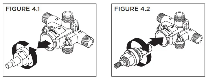
Installation – Remove Test Cap (Model Numbers Ending in TRMTC)
Flow control spindle (TA-10) and cap assembly (T-12A) will come factory assembled for all model numbers ending in TRMTC. When ready to remove Test Cap and install trim, follow the instructions below:
- Check for leaks around the valve assembly and all pipe fittings.
- Remove test cap from valve (FIGURE 4.1).
- If the system is dirty, flush the valve.
- Thread flow control spindle and cap assembly into the valve body. Turn clockwise to secure to valve (FIGURE 4.2).
Installation – Adjust Packing Nut (Model Numbers Ending in TRMTC)
- Turn hot and cold supplies on. Valve will not operate unless both hot and cold water supply pressures are on.
- Place handle overflow control spindle.
- Tighten packing nut for positive frictional resistance as the handle is rotated from shut-off position across adjustment range
Installation – Setting Limit Stop Screw (Model Numbers Ending in TRMTC)
The temperature limit stop screw limits valve handle from being turned to the maximum position resulting in excessive hot water discharge temperatures.![]() WARNING: Failure to adjust the limit stop screw properly may result in serious scalding.
WARNING: Failure to adjust the limit stop screw properly may result in serious scalding.
- Turn hot and cold supplies on. Valve will not operate unless both hot and cold water supply pressures are on.
- Place the handle on the flow control spindle and open the valve to the maximum desired temperature.
- Turn limit stop screw clockwise until it seats.
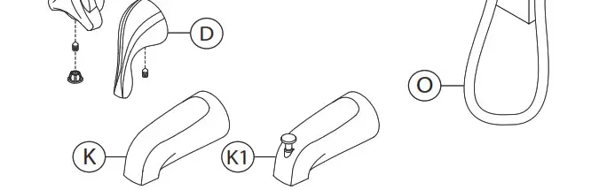
Parts Breakdown
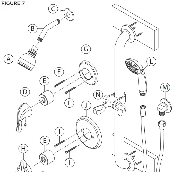
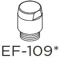
*Order in-line vacuum breaker (EF-109) for hand shower systems without dual checks.
Replacement Parts | ||
Item | Description | Part Number |
| A | Showerhead | 4-141 |
| B C | Shower Arm Flange | 300S |
| D | ‘PLR’ Handle | RTS-063 |
| E | Dome Cover | T-19 |
| F G | Diverter Escutcheon Screws | 96-66-DIV-ESC |
| H | ‘P’ Handle | RTS-061 |
| I J | Shower Escutcheon Screws | Standard: 9600-P-ESC Brass: 9600-P-B-ESC |
| K K1 | Tub Spout Diverter Tub Spout | 060 054 |
| L | Hand Shower | ADACHS |
| M | Wall Elbow | 40A |
| N | Slide Mechanism | FP-SM6 |
| 0 | 60″ Hose | RTS-045 |
Notes:
- Append appropriate suffix for a premium finish.
- Append appropriate flow rate to the showerhead or hand shower for low flow.
- Apply a bead of silicone around the perimeter of all shower trim installed flush to the finished wall. Leave an opening on the bottom of escutcheons for weep hole.
- Apply plumber tape to all threaded connections.
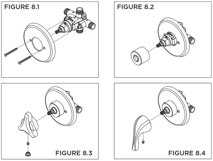
Installation – Shower Valve Trim
- Secure large shower escutcheon to Temptrol pressure-balancing valve using mounting screws (FIGURE 8.1).
- Install dome cover by turning clockwise (FIGURE 8.2).
- Install ‘P’ handle to the shower valve. Secure with set screw. Install plug button (FIGURE 8.3).
- Install ‘PLR’ handle to the shower valve. Secure with set screw (FIGURE 8.4).
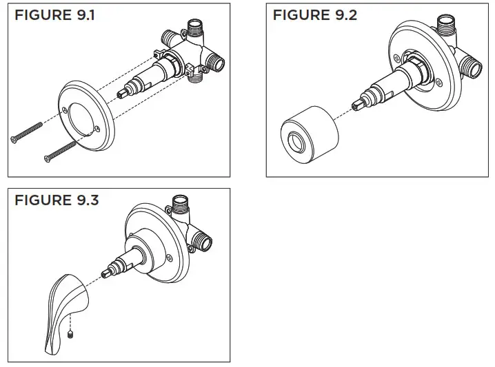
Installation – Diverter Valve Trim
- Secure small diverter escutcheon to Symmons diverter valve using mounting screws (FIGURE 9.1).
- Install dome cover by turning clockwise (FIGURE 9.2).
- Install the handle to the diverter valve. Secure with set screw(FIGURE 9.3).
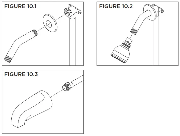
Installation – Showerhead & Tub Spout
- Attach arm and flange to shower pipe. Turn clockwise to tighten (FIGURE 10.1).
- Install showerhead to shower arm. Turn clockwise to tighten (FIGURE 10.2).
- Install tub spout to stub out pipe. Turn clockwise to tighten (FIGURE 10.3).
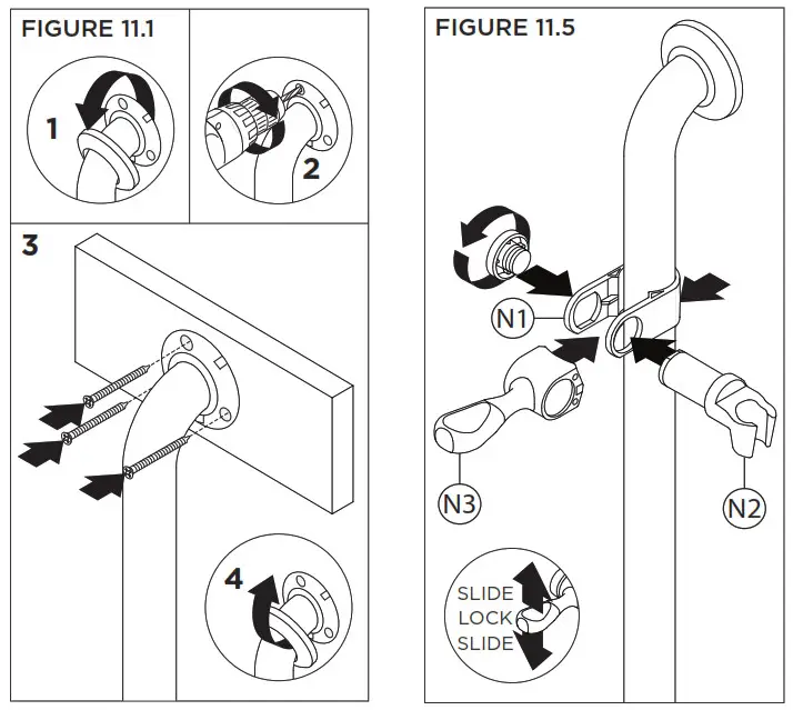
Installation – Slide Bar Assembly
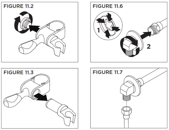
- Remove slide bar ends from slide bar flanges. Using flanges as a guide, drill 1/8″ pilot holes into studs or wood blocking. With slide bar in position, secure to wall using screws. Attach slide bar ends to bar flanges (FIGURE 11.1).
- Remove the screw cap from slide mechanism (FIGURE 11.2).
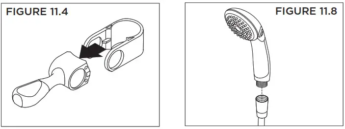
- Remove the wand holder from the slide mechanism (FIGURE 11.3).
- Remove lever handle from slide mechanism (FIGURE 11.4).
- Install slide mechanism components to slide bar following STEPS 11.2 – 11.4 in reverse. Flat edge on (N1) and (N2) must be aligned. Arrows on (N1) and (N3) identify the bottom side (FIGURE 11.5).
Note: Adjust the screw cap for ease of movement of the slide assembly. - Press tabs on wall elbow flange. Install wall elbow to pipe fitting. Turn clockwise to secure (FIGURE 11.6).
- Attach small end of hand shower hose to wall elbow.
Turn clockwise to tighten (FIGURE 11.7). - Attach large end of hand shower hose to hand shower wand. Turn clockwise to tighten (FIGURE 11.8).
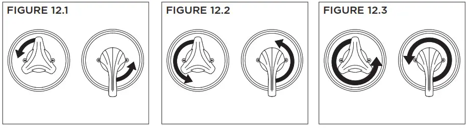
Operation (Temperature Control)
- Turn shower handles counter-clockwise approximately 1/4 turn to put the valve in cold position (FIGURE 12.1).
- Turn shower handles counter-clockwise approximately 1/2 turn to put the valve in a warm position (FIGURE 12.2).
- Turn the shower handle counter- clockwise approximately 3/4 turn to put the valve in hot position (FIGURE 12.3).
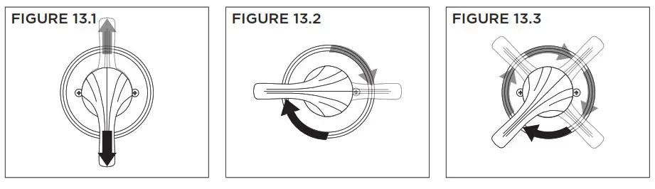
Operation (Dual Outlet Diverter Control)
Note: Additional handle positions for the same output are illustrated.
- The cartridge is factory set to divert to function 1 (FIGURE 13.1).
- Turn the handle to position 2 to divert to function 2 (FIGURE 13.2).
- Turn the handle to position 3 to share functions 1 and 2 (FIGURE 13.3).
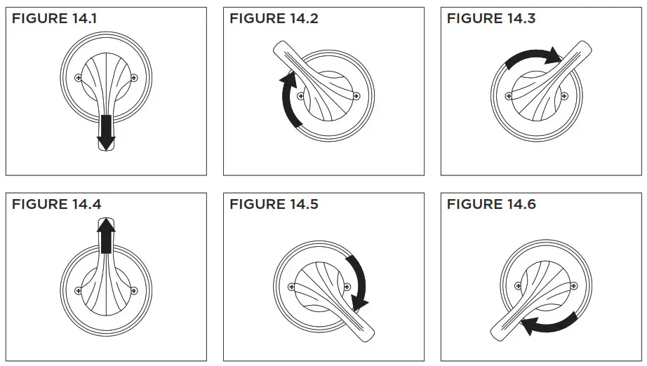
Operation (Triple Outlet Diverter Control)
- Cartridge is factory set to divert to function 1 (FIGURE 14.1).
- Turn handle to position 2 to divert to function 2 (FIGURE 14.2).
- Turn handle to position 3 to divert to function 3 (FIGURE 14.3).
- Turn handle to position 4 to share functions 2 and 3 (FIGURE 14.4).
- Turn handle to position 5 to share functions 1 and 3 (FIGURE 14.5).
- Turn handle to position 6 to share functions 1 and 2 (FIGURE 14.6).
Troubleshooting Chart Problem
| Problem | Cause | Solution |
| Finish is spotting. | Elements in the water supply may cause water staining on the finish. | Clean finished trim area with a soft cloth using mild soap and water or a non-abrasive cleaner and then quickly rinse with water. |
![]() WARNING: This product can expose you to chemicals including lead, which is known to the state of California to cause cancer, birth defects, or other reproductive harm. For more information, go to www.P65Warnings.ca.gov.
WARNING: This product can expose you to chemicals including lead, which is known to the state of California to cause cancer, birth defects, or other reproductive harm. For more information, go to www.P65Warnings.ca.gov.
Symmons Industries, Inc.
- 31 Brooks Drive
- Braintree, MA 02184
- Phone: (800) 796-6667
- Fax: (800) 961-9621
Copyright © 2019 Symmons Industries, Inc. - symmons.com
- [email protected]
- ZV-3295 REV 0
- 020119


