GASLAB PRO 100% CO2 – CM-1000-00-00-25-00 Series Multi-Gas Sampling DataLogger
WELCOME
Thank you for selecting the CM-1000 Gaslab® Pro, Multi-Gas Sampling Data Logger. The CM-1000 series is designed to simultaneously measure multiple gas concentrations through a sampling method. This device features Li-ion rechargeable batteries which allows for 30+ hours of use.
The CM-1000 series data can be recorded to a micro SD card for retrieval and analysis. The full color LCD display details each sensor’s reading as well as graphing the data on the screen. The CM-1000 was designed for applications like fire suppression testing, fumigation, scientific research, laboratory analysis and incubation.
At CO2Meter, we approach each customer’s application as a unique opportunity to understand, educate, and provide product solutions that meet the customers’ needs while exceeding their expectations for reliability and service. Our continued product innovation in combination with our “customer first” focus allows CO2Meter, Inc. to continue to provide solutions for the future.
Based in Ormond Beach, FL, CO2Meter, Inc. is committed to the success of our customers as well as; the health, welfare, and prosperity of our talented employees; and the continued development of our local community.
CO2Meter, Inc. appreciates your business and looks forward to working with you and your team in the future.
Please take some time to read through this manual to become familiar with the Multi-Gas Sampling Data Logger. Also, please pay special attention to the important safeguards.
IMPORTANT SAFEGUARDS
To reduce the risk of fire, electrical shock and/or injury to persons, basic safety precautions should always be followed when using electrical appliances, including the following:
- READ ALL INSTRUCTIONS BEFORE USING THIS METER.
- Use only the included power supply to operate this meter. Inappropriate voltage supply could cause irreparable damage to this device.
- Do NOT use batteries other than the Li-ion 18650 3.7V rechargeable batteries
- Additional Li-ion 18650 3.7V rechargeable batteries (3) (can be purchased, here)
- Do not operate with an obstructed sample path. remove the luer caps prior to operation.
- Make sure that the tubes are securely attached to the meter before sampling a closed environment.
- Ensure the SD Card has the gold chips facing up and towards the user, for properuse.
- This meter is not designed for prolonged outdoor use.
- Do not expose this meter to water or any liquids utilize the included filters and water traps.
- Do not operate this meter if the enclosure is opened.
- Do not operate the device if it is malfunctioning.
SAVE THESE INSTRUCTIONS!
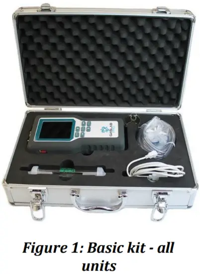
PACKAGE CONTENTS
Please verify that your package contains the following items before using the meter:
ALL UNITS:
- (1) CM-1000 Multi Gas Data Logger
- (3) Li-ion 18650 3.7V batteries (Installed)
- (1) Water Trap
- (1) Hydrophobic Filters
- (2) Particulate Matter filters
- (2) Barbed fittings for filters
- (1) Tubing Set 6′
- (1) 16 GB SD Card
- (1) SD Card Adapter
- (1) Manual
- (1) USB 1.5 cable
- (1) Carrying Case with keys
OPTIONAL ACCESSORIES
If the meter is to operate in environments where humidity is very high (>95% RH), an Extreme Moisture Trap can be purchased separately. This filter will allow free flow of sampled air while keeping moisture out of the meter.
Note: Please contact our technical support staff for more details about these accessories, [email protected]
FEATURES
- Measures CO2, CO, O2, CH4, RH, AMB, DP and ALTI (Dependent upon device model)
- Options for CO2 measurement range: 1%, 5%, 10%, 20%, 30%, and 100%
- Large back-lit LCD Display, for easy reading of gas concentration, temperature, and humidity
(Additional Li‐ion batteries may be purchased individually, here.) - On-board, built-in 2-graph data logging display
- Supplied with Li‐ion 18650 3.7V rechargeable batteries, for longer lifespan
- Audible and Visual Alarms
- Data Logging to any size micro SD Card (16GB SD Card included)
PRODUCT OVERVIEW
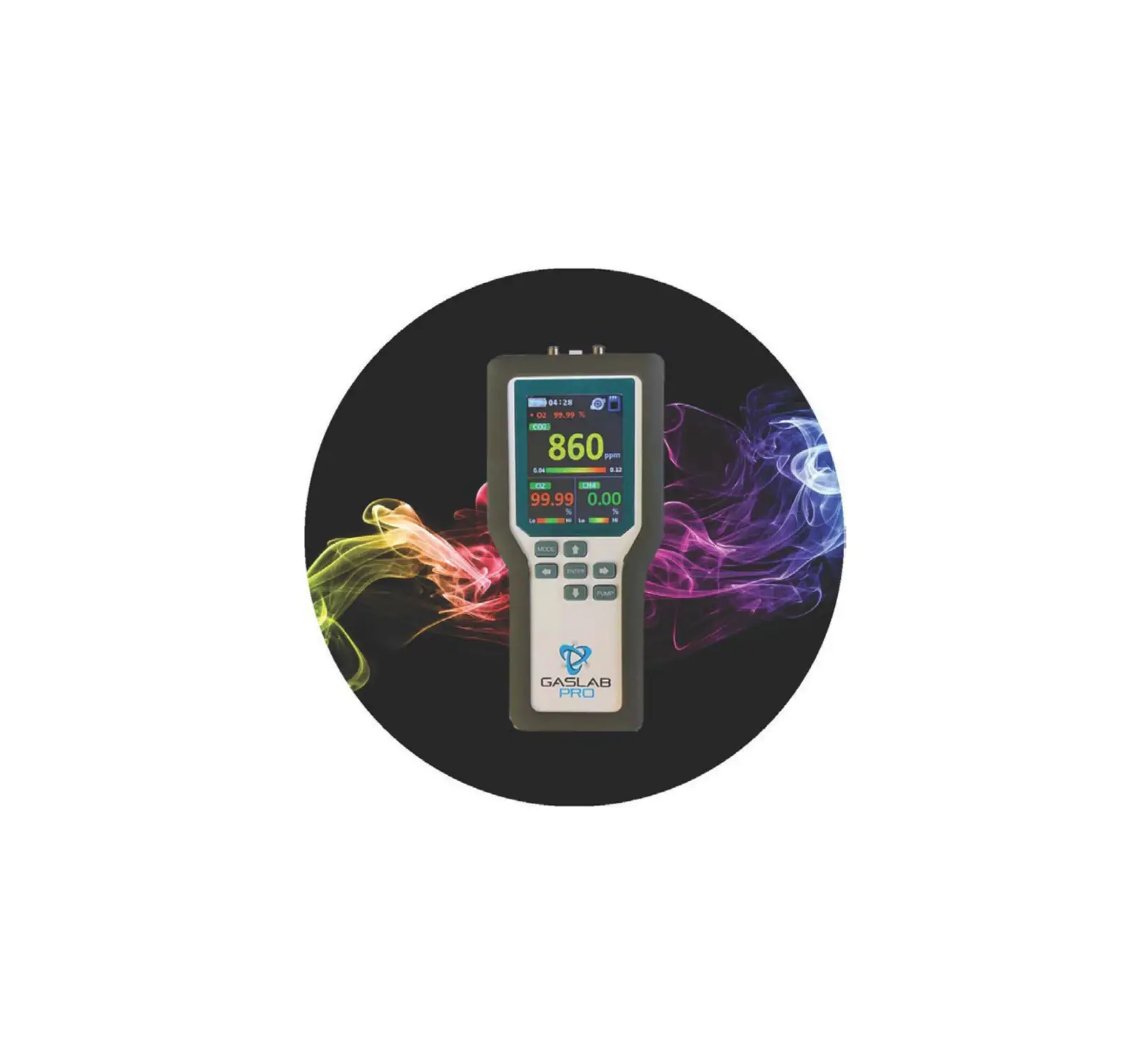
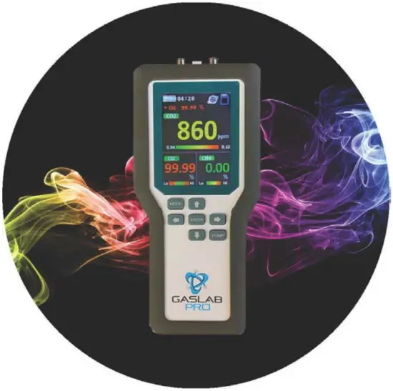
The GasLab® Pro Multi-Gas Sampling Data Logger is designed to simultaneously measure multiple gas concentrations through a sampling method. Utilizing a micro pump, the device draws samples into the sensing chambers allowing each sensor to take a fast and accurate measurement of the sample.
Meters with logging capabilities are designed to record data over extended periods of time to a 16GB micro SD card. The SD card stores an indefinite amount of collected data points that can be retrieved later for analysis.
Real time data and graphing is available on all CM-1000’s by rotating the device to a horizontal position.
The meters are ideal for applications such as, but not limited to monitoring of products with modified atmosphere packaging (MAP), bio incubation, industrial, and testing of fire suppression systems.
The devices built-in micro-pump ensures reliable operation and consistent readings based on user-selected time intervals.
PRINCIPAL OF OPERATION
The sensors inside this device use advanced sensing technologies to sense, as a function of transmitted light, or by fluorescence quenching by oxygen to identify the precise gas concentrations in a sampled setting.
Samples are pulled in through the tube inlet port and draw into the detection chamber by a micro-pump, then expelled through the tube outlet port. Ensure that the luer caps are both removed prior to operating the device. Failure to do so will provide incorrect readings and may result in damage to the device.
The measured gas concentration levels are shown on the full color LCD display section in real time and/or logged into micro SD memory card for later retrieval.
The device is factory calibrated immediately prior to shipping and will operate within the specified range and precision upon its arrival.
INSTRUMENT OVERVIEW
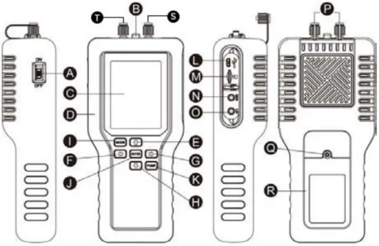
A. Power Switch On/Off
B. Temp/Humidity Sensor
C. LCD Displays Screen
D. Rubber Enclosure
E. Up Key
F. Left Arrow Button
G. Right Arrow Button
H. Down Arrow Button
I. Mode Button
J. Enter Button
K. Pump Button
L. USB Socket
M. SD Card Slot
N. Programming Port (INTERNAL use only)
O. 4-20mA Connection
P. Luer Caps
Q. Battery Cover Screw
R. Battery Cover
S. Inlet Cap
T. Outlet Cap
| MODE (Ⓘ) | Enter the setting menu. |
| Up (Ⓔ) / Down (Ⓗ) / Left (Ⓕ) / Right (Ⓖ) | Change parameter values or select options. |
| Enter (Ⓙ | Execute a command |
| PUMP (Ⓚ) | Start the pump or data logger (Does notturn pump off, must wait for sample period) |
LCD Display
The Full Color Liquid Crystal Display (LCD) shows the following features:
- CO2 concentration level in parts‐per‐million (ppm or %)
- O2/CO/CH4 concentration levels in percentage format (##. ##%)
- RH, AMB, DP. and ALTI
- Time, Battery Life (upper left)
- SD Card Logging Icon ON/OFF (upper right)
- Sampling Pump Active/Inactive (upper right)
- Percentage of batteries
Main LCD Display Screen
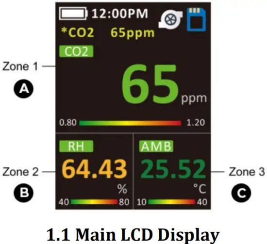
A. Zone 1 – Gas ConcentrationDisplay
B. Zone 2 – Gas Concentration or RH/T
C. Zone 3 – TEMP / BARO / DP
Built-In Data Log Screen
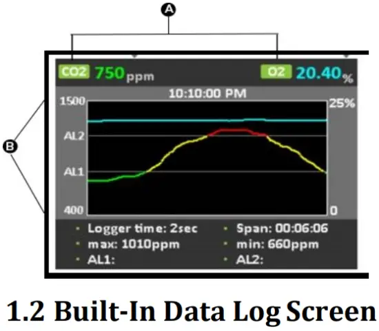
A. Gas Concentration Levels (ppm or %)
B. Y Axis – PPM and Alarm Levels
C. X Axis – Logger Time / Span
QUICK START GUIDE
- Install filters and tubing included if necessary.
- Turn the meter ON by switching the red power switch up on the left of thedevice.
- Turn logging ON by pressing the PUMP button until the SD Card Icon displays a green inner square.
When the sampling process is completed, you can hold the PUMP button until the SD Card Icon turns solid white. - When the SD Card is White, the pump will stop after 60 seconds of sampling. (user is able to set the sampling period to any time length).
POWERING THE METER
- Power on: Switch the Red Power Button ( A ) Up, located on the left side of the device, to the UPposition.
- To turn off, Switch the Power Button ( A )Down.
- This device uses Li‐ion rechargeable batteries, which can provide a 30+ hours charge.
*Please note – when the device is charged with a USB cable it cannot be turned off*
OPERATION
Make sure you read through these instructions thoroughly before using the device. This guide will help you become more familiar with the device’s operation. Please read the Important Safeguards on page 3 before continuing.
IMPORTANT: Follow these instructions to ensure proper set up:
- After powered on, when pump is activated, the device will measure the data in real‐time.
- Before getting started you need to enter the settings screen, by holding the Mode Button (I), to alter the settings of the device.
- Utilize the UP and DOWN arrow buttons to highlight the appropriate settings you wish to update. Once selected, the appropriate setting will be highlighted in purple and can be altered by using the UP and DOWN buttons.
Once the appropriate settings have been selected, press and hold the MODE button to return to the main display screen.
*Please note, you may wish to navigate to “auto power off” and “back‐light time” in the settings screen to change the standard 30 second time / 60 minutes period to any custom length interval for non‐ interference
On the main display you will notice 3 zone squares:
‐ Zone 1 (top display sensor area) Zone 2 (bottom left ‐ RH) and Zone 3 (bottom right ‐ DP/AL/AMB)
- To select a zone, use the Left (F) / Right (G) arrow buttons to select the parameter/ sensor to
be adjusted, the zone will be highlighted in red. - Next, you can press the Right arrow button (G) to proceed to alter the settings use the Up (E)/Down (H) arrow buttons to edit the parameter values or alarm levels for that zone.
DISPLAY ALL SENSOR READINGS
- Press/hold the ENTER button ( J ) to display all sensor readings. Press the MODE button ( I ) to return to
the main screen. (See reference chart below, for factory default setting
DATA STORAGE
This device features an included 16GB micro SD card; however, any size micro SD card can be utilized.
Once the GasLab® Pro Multi Gas Sampling Data Logger is turned on, you can gather data in real time. Data logs can be downloaded from the device’s micro SD Card to an excel/csv. file and analyzed for further observation. The full color LCD display also features real‐time data graphing by rotating the device to the horizontal position.
Before Logging
- Verify the 16 GB SD Card is installed in the card slot correctly.
(The gold tabs should point towards the front of the device/user ‐ see, 1.3 image) - Verify the batteries are fully charged before deployment. Charge/replace if necessary.
Measuring
- Turn the CM‐1000 series red power switch “ON”.
- Remove the luer caps on the top of the device from Inlet and Outlet ports.
- Ensure that the PUMP is running, as accurate measurements cannot be made unless the PUMP key has been turned on.
- Verify the CM‐1000 displays GAS(S)/RH/TEMP on the mainscreen
Recording Data
- Place the CM‐1000 Multi‐Gas Sampling Data Logger in its desired location.
- Connect the included tubing and filters as required to the top ports. (see image on page10).
- To begin logging, press and hold the PUMP button.
The inner square of the SD Card Icon in the top right‐hand corner of the screen, will change color and thpump icon will begin to spin. - When the SD card icon inner square is green, the CM‐1000 is recording data.
- If the SD card icon inner square is red, this means that the SD card is damaged, missing, or full of data.
- When the SD card icon is green, the pump will runcontinuously.
- To stop logging, press and hold the PUMP button until the SD Card icon changes color.
- When the SD card is White/Red the data is not being recorded.
- Should the user wish to turn off the data logging feature, press and hold the PUMP key. The SD Card will appear
White, and the pump will stop after 60 seconds of sampling.
Managing Files
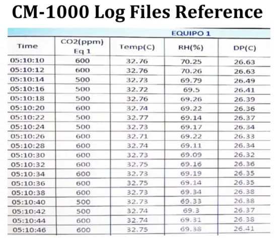
- The CM‐1000 series stores “Log Files” on the removable SDcard.
- The excel/csv. columns are pre‐labeled: Time / Gas Concentration / RH%/DP (C), Baro1 (ambient air)/ Baro2 (pressure inside the sensing chamber)
- At the completion of your tests, remove the SD Card from theCM‐1000.
- Place the SD card into the included card adapter or simply place into your PC.
- Open the Log files in Excel (.xlsx)
- Success! You have downloaded/managed the data you recorded with your CM-1000 Series Multi-Gas Sampling Data Logger.
SETTINGS
The settings screens will allow the user to access all the parameters, options, outputs, communications, and date/time settings available in the device.
The settings screen allows you to change the brightness and back‐light color themes (4 available) on the device, as well as activate a back‐light time specifically to save power. This setting will not affect the meter’s functionality but will affect the battery life depending on how you set this parameter.
Additionally, you can alter the date/time, graph line settings, and flow rate levels.
ENTERING SETTINGS SCREEN
- Press/hold the MODE button ( I ) to enter the setupmenu.
- Press the MODE button ( I ) to enter to the next page2/2.
- Press the UP / DOWN buttons to select options or change parametervalues.
- Then press the ENTER button ( J ) to confirm it. Press/hold Mode button ( I ) to return to the main scree
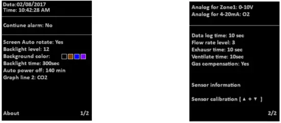
The first page (1/2 – Date/Time)
| Default Settings | ||
| Date/Time | 01/01/2017 ~2099 / 12/24-hour time | Pre-Set by CO2Meter |
| Continue alarm | Yes (The buzzer sounds continuously.) / No (The buzzer sounds once.) | NO |
| Screen auto rotate | Yes / No | YES |
| Backlight level | 1~32 (The larger the number, the brighter the screen) | 11 |
| Background color | (There are a total of 4 background colors.) | Black |
| Backlight time | 10~999 sec (Backlight display time) | 30 seconds |
| Auto power off | 1~999 min | 60 minutes |
| Graph line 2 | CO2/ O2/CO/ CH4 (The second trend line shows the gas measurements.) | Graph line 2 set to O2 |
| About | CO2Meter – www.co2meter.com | N/A |
| The second page (2/2) | ||
| Analog for Zone 1 | 0-10V/4~20mA (Zone 1 voltage or current output) | 0-10V |
| Analog for 4-20mA | CO2/O2/CO/CH4 (Another analog output option) | CO2 |
| Data log time | Data logging interval time | 2 seconds |
| Flow rate level | 1~5 (The larger the number, the greater the pump output) | 5 |
| Exhaust time | 10~240 sec | 60 seconds |
| Ventilate time | 0~120 sec | 0 seconds |
| Gas compensation | Yes / No (CO2 and O2) | NO |
| Sensor times info | Sensor recalibrated time and pump lifetime (The time is displayed in the countdown mode. If you need to calibrate the sensor or exceed the pump lifetime, the time will be displayed in red.) CO2: 99999999 days O2: 99999999 days CO: 99999999 days CH4: 99999999 days Pump: 99999999 min | Default |
| Reset to factory | Yes / No (Recover the factory setting to cancel customize setting.) | Reset to factory |
| Sensor calibration (▲+▼) | Please refer to the calibration section. | Sensor calibration (▲+▼) |
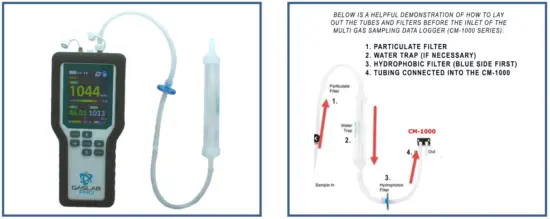
USING THE FILTERS
To use this device properly, hoses/tubing must be attached to the inlet and outlet barb fittings securely.
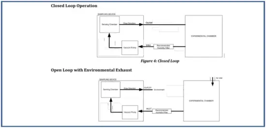
The device was shipped with extra luer fittings if they are needed. The micro pump inside the device will draw air from the inlet by vacuum effect, push it through the sensing chamber, and then exhaust the air outside the meter through the outlet port. Below are examples of the options for exhausting the sampled air; closed vs. open loop.
A closed loop system will remove a sample from a chamber or line, sample the gas, and return the sample back to the chamber or line.
An open loop system will remove a sample from a chamber or line, sample the gas, and eject the sample to ambient atmosphere.
CALIBRATION
All units are shipped factory calibrated. Factory calibration certificates are saved on the SD card included with your device.
Over time all sensors require recalibration to maintain their accuracy and repeatability. When it is time to re‐ calibrate, end users have two choices: field/self‐calibration OR returning the device to CO2Meter for factory calibration.
WHY IS CALIBRATION REQUIRED?
Our Sampling Data Loggers use highly accurate and technologically advanced sensors. These rely on a variety of technologies to detect and measure the concentrations of your desired gas. Over time, these technologies can deteriorate to the point that they must be moved back to a standard point of reference.
To combat sensor drift, a well‐planned and documented process is used to return the sensor as close to its intended operational state as possible.
1 POINT & 2 POINT CALIBRATION
There is a distinguishable difference between 1‐point and 2‐point calibration methods. One‐point sensor calibration involves applying one reference gas, whereas 2‐point calibration is done by provided two reference gases to the device for the sensor to stabilize or move back to a standard point of reference.
For 1‐point calibration, the most accurate method is to expose the device to pure 100% nitrogen to accurately stabilize the sensor. CO2Meter utilizes 2‐point calibration prior to shipping each CM‐1000 device. This method is much more comprehensive and should only be followed if you are an advanced user. We recommend that the CM‐1000 series be calibrated, annually.
(See step‐by‐step CM‐1000 1 Point Calibration guide below page. 12)
As mentioned, for 2‐point calibration CO2Meter requires that this method be performed if you are an advanced or experienced user who has performed this method multiples times prior.
We recommend contacting CO2Meter for the 2‐point calibration guidelines or reach out to us directly to calibrate the device at a nominal fee. You can reach us directly at, [email protected] or (877) 678 ‐ 4259.
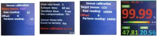
User Calibration – CM-1000 – 1 Point Calibration
The CM-1000 GasLab® Pro Multi Gas Sampling Data Logger Series is calibrated using 100% CO2 Gas
To enter 1‐Point Calibration Mode, please follow the appropriate steps below:
- Turn on CM‐1000 and wait for display toinitialize.
- Press and hold Mode (I) until first menu page appears ‐ confirm the screen shows”1/2″.
- Press Mode (I) again, and the second menu page will appear ‐”2/2″.

- Press the Down arrow button (H) to scroll until “Sensor Calibration” is highlighted inRed.
- Press the Enter button (J) and “Sensor Calibration” will now be highlighted inPurple.
- Next, simultaneously press and hold both the UP (E) and Down (H) arrows at the same time to enter the specific “Sensor Calibration” page.
- Press the Enter button (J) to highlight “Target Sensor” inRed.

- Press the Down arrow button (H) to scroll through the available sensors, for 100% we will press the down button until “CO2” appears.
- Press the Enter button(J) to select the desired target sensor.
- Next press the Down arrow button (H) to highlight “Offset” inRed.
- Connect your inlet port to a source of gas, such as 100% CO2 and wait for readings tostabilize.
- Press the “Up” or “Down” arrow buttons to adjust the “Perform Reading” (ex. for CO2, read10000).
- Press and Hold the Enter button (J) to return to the main displayscreen.
- The CM‐1000 series will now display approximately99.99%.
- Remove the 100% CO2 from the Inlet Port.
- Congratulations, you have successfully calibrated theCM-1000!
SPECIFICATIONS
|
Measurement Range & Accuracy | CO2: 1%, 5%, 10%, 20%, 30%, 100% |
| CO: 0~1,000ppm | |
| O2: 0~25%, < 2% FS / 0.1 mbar | |
| CH4: 5% 0-1%: ≤±0.1% | |
| RH: 0~100%, ±3% @25°C (20~80%RH), others ±5% | |
| Temperature: 0~50°C,±1℃ | |
| Barometer: 50~110kPa, ±0.4kPa | |
| Display Resolution | CO2: 1ppm, 10ppm, or 100ppm |
| CO: 1ppm | |
| O2: 0.01% | |
| CH4: 0.01% | |
| RH: 0.01% | |
| Temperature: 0.01°C | |
| Barometer: 0.1mmHg | |
| Alarm Volume | 80db±5%@10cm |
| Operating Conditions | 0~50°C(32~122°F), 0~95%RH, non-condensing |
| Storage Temp. | -20~60°C(-4~140°F) |
| RS485 CO2Meter Internal | RS485 ModBus BR19200 |
| Power Supply | Rechargeable Battery: Li-ion 18650 3.7V |
| AC Adapter: 5V±5% >1A, 100~240 VAC, 50/60 Hz | |
| Storage Capacity | depend on SD card capacity (max.16G SD card) |
| Weight | 480g (1.05 lbs.) – without batteries |
| Dimensions | 225.8×99.6×55 mm (8.9 x 3.9 x 2.2 in.) |
CM-1000 Pump Pneumatic Data
| Max. Flow | 500 ml/min |
| Max intermittent duty | 380 to 400 mbar |
| Max. continuous pressure | 150 mbar |
| Max. restart pressure | 150 mbar |
| Max. vacuum | -360 to -400 mbar |
| Max. restart vacuum | -150 mbar |
Electrical / General Data
| Motor type | Standard DC |
| Rated power | 3.5 to 5 V/90 mA |
| Protection class | IP00 |
| Ambient Temperature | 10 to 50°C |
| Media Temperature | 10 to 50°C |
| Weight | 17g (0.03lb) |
Note: After power-on, it takes 20 minutes for the device to stabilize and measure the temperature and relative humidity, accurately.
EMC/RFI: Readings may be affected if the unit is operated within radio frequency electromagnetic field strength of approximately 3 volts per meter, however the performance of the instrument will not be permanently affecteD.
| Symptom / Issue | Possible Cause / Resolution |
| Pump does not ACTIVATE | If the user experiences issues with pump activation, press/hold the MODE key to enter into settings screen. Click ENTER to access 2/2 and modify “Flow Rate Level” to “5”. If pump is still inactive, pump needs to be replaced – contact [email protected] |
| Device does not power ON | Make sure the power supply is connected properly and that there is power in the outlet the adapter is connected has the appropriate voltage. If using batteries, make sure they are not depleted. |
| Slow response | Check the air flow channels to make sure they are not obstructed. |
| Reading Error | Ensure that the Inlet/Outlet Luer Cap Fittings are removed to enable an accurate means of sampling. |
| Red SD Card Icon Appears | This indicates that the SD Card is either damaged, missing, or full of data. Replace SD Card. |
| LCD Display Turns Off During Measurements | If the user experiences LCD display turning off during calibration, measurements, or data logging – please reference the “settings” section to adjust backlight / auto power off from default settings. |
| LCD Screen Troubleshooting During Use | If the user experiences issues with the screen orientation, this setting can be changed by referencing the “settings” section and adjusting the “screen auto rotate” to “NO”. |
Rechargeable Batteries Index

‘Battery OK’: Measurements are possible
 ‘Battery Low’:
The battery needs to be recharged, measurements are still possible
 ‘Battery Exhausted’:
Measurements are not possible
Battery installation:
This device is supplied with Li-ion 18650 3.7V rechargeable batteries (3x), which are pre-installed upon device shipment.
Battery charging:
During battery charging, the temperature of the device will rise by 5°C~10°C. At this time, the measurements of
temperature and humidity will be affected by temperature rise. This could cause an effect on the accuracy of temperature when charging. Please use a fan to blow toward the Temperature & Humidity Sensor (B ) directly, in order to gain a compensated balance of temperature and humidity between that of the temperature sensor and surrounding area. (5V/1A USB adapter charger).
Safety and Product Care
To ensure correct and safe device use, please read the User Manual before using the device. Please handle the device lightly, do not subject the device to impact/shock.
- Do not submerse the device in water or allow liquid to be sampled into the device.
This will cause electric shock, fire or malfunction which may result in damage. - Do not keep the device in a hot/humid environment. Keep the device away from heat source or water.
- Please use a standard USB power supply (such as PC’s USB port, universal AC adapter with USB port).
- Improper powers upply can cause serious damage to thedevice orresultin injuryordeath to theuser.
Product Maintenance
- The maximum capacity of the SD card is 16G. (This is five years’ worth of space)
- During battery charging, the temperature of the device rises. The temperature and humidity sensors are affected.
Currently, measurements are only for reference. After batteries are fully charged and the device cools down, measurements are reliable. - Repair – Do not attempt to repair the device or modify the circuitry by yourself. Please contact CO2Meter if the device needs servicing.
- Caution – The CO sensor must be replaced every 3 years.
- Cleaning – Disconnect the power before cleaning. Use a damp cloth, do not use a liquid cleaning agent, such as benzene, thinner or aerosols.
- Maintenance – Recommended that the user conducts a comprehensive test and calibration every year to ensure normal operation of the device
CONTACT US
We are here to help!
For information or technical support, please contact us.
![]() (386) 256‐4910 (Technical Support)
(386) 256‐4910 (Technical Support)![]() (386) 872‐7665 (Sales)
(386) 872‐7665 (Sales)
![]() www.co2meter.com
www.co2meter.com
See CO2Meter, Inc. Terms & Conditions at,
www.CO2Meter.com/pages/terms‐conditions
Address:
CO2Meter, Inc.
131 Business Center Drive
Ormond Beach, FL 32174
USA