![]() NDIR Infrared CO2 Gas Sensor
NDIR Infrared CO2 Gas Sensor
(Model:MH-441D-LOW)
Manual
Version: 1.0
Valid from: 2020.09.14
Statement
This manual copyright belongs to Zhengzhou Winsen Electronics Technology Co., LTD. Without the written permission, any part of this manual shall not be copied, translated, stored in database or retrieval system, also can’t spread through electronic, copying, record ways.
Thanks for purchasing our product. In order to let customers use it better and reduce the faults caused by misuse, please read the manual carefully and operate it correctly in accordance with the instructions. If users disobey the terms or remove, disassemble, change the components inside of the sensor, we shall not be responsible for the loss.
The specific such as color, appearance, sizes &etc, please in kind prevail.
We are devoting ourselves to products development and technical innovation, so we reserve the right to improve the products without notice. Please confirm it is the valid version before using this manual. At the same time, users’ comments on optimized using way are welcome.
Please keep the manual properly, in order to get help if you have questions during the usage in the future.
Introduction
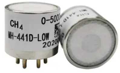
MH-441D infrared gas sensor is a miniature universal intelligent sensor, which adopts NDIR theory to detect concentration of CH4 in air and has good selectivity, stable performance, long life, also is independent of Oxygen. The inside temperature sensor could be used for temperature compensation. This miniature infrared gas sensor is developed by the tight integration of mature infrared absorbing gas detection technology, micro machine workout and superior circuit design.
It is convenient in use and also instead of catalytic component directly, widely used in various occasions with flammable and explosion hazard gas.
Features
- High sensitivity, high resolution, low power consumption, Fast response time
- Output method: UART, analog voltage signal
- Temperature compensation, excellent linear output
- Long lifespan, Excellent stability, Anti-poisons, anti-vapor interference
Applications
Widely used for HVAC refrigeration, industrial-process control and safety protection, agriculture and animal husbandry.
Main Parameters
Table 1
| Model | MH-411D-LOW |
| Detection Gas | CO2 |
| Working Voltage | 3.6-5V DC(Need to be powered by safety barrier) |
| Average Current | <30 mA |
| Detection range | 0-10%vol Optional(refer Table 2.) |
| Interface Level | 3.0V |
| Output Signal | UART |
| 0.4-2V(Need to be powered by safety barrier) | |
| Warm-up time | 3 min |
| Response time | T90<30s |
| Working Temperature | -20°C —60°C |
| Working Humidity | 0″95%RH(no condensation) |
| Sizes | 020 mmx22.2 mm |
| Weight | 35g |
| Lifetime | >5 years |
| Defense Grade | IP54 |
| Power, communication terminal Intrinsic safety | Ui=7.5VDC, Ii=265mA, Pi=0.5W, Ci=10 μF, Li=0mH |
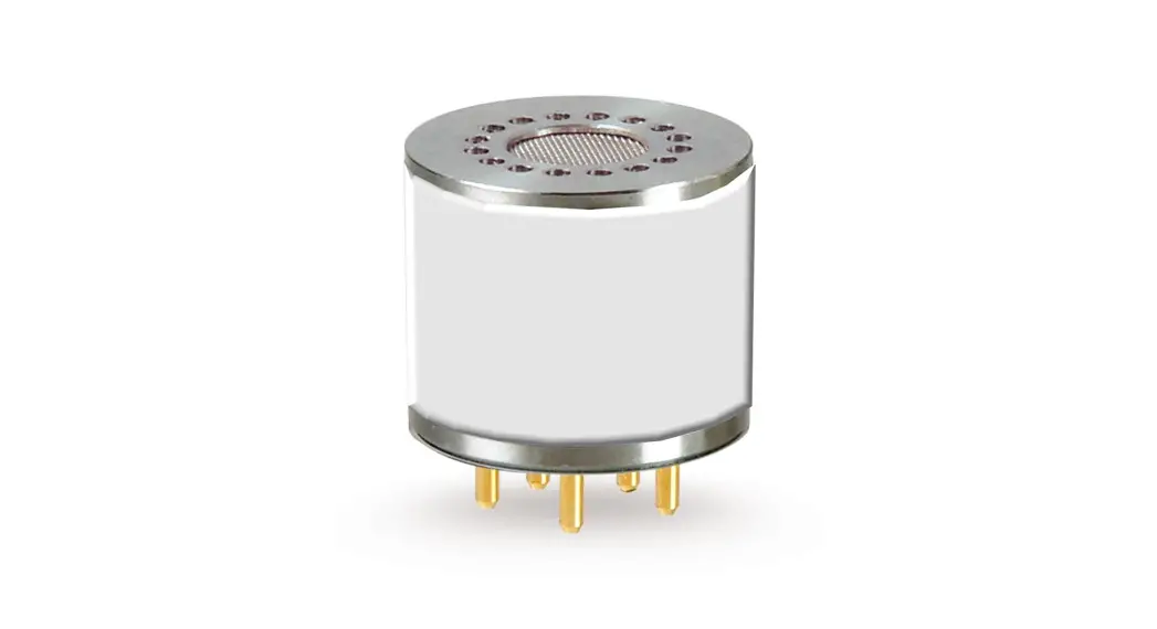
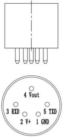 Figure 1: Sensor Structure diagram
Table 2.Measuring Range and Resolution
| Target Gas | Measuring Range | Resolution | Decimal places | Remark |
| CH4 | 0-5%VOL | 0.01% VOL | 2 | Temperature compensation |
| 0-10%VOL | 2 | |||
| 0100%LEL | 1%LEL | None |
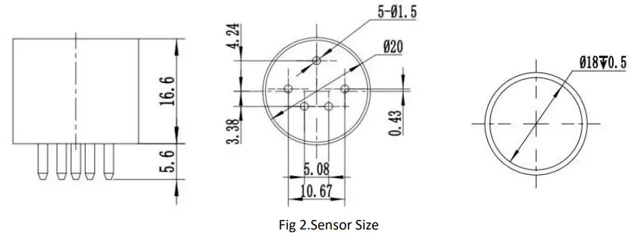
Structure Size
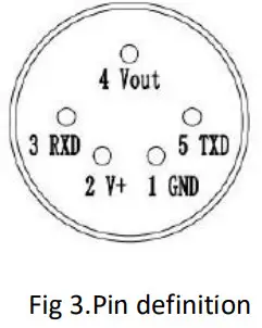
Pin definition
Table3.Pin definition
| Name of Pin | Explanation |
| Pin 2 | V+ Voltage input |
| Pin 1 | GND |
| Pin 4 | Vout (0.4-2 V) |
| Pin 3 | UART ( RXD ) 0-3.0 V data input |
| Pin 5 | UART ( TXD ) 0-3.0 V data output |
Analog voltage output
The output of Vout is proportional to the gas concentration, 0.4-2.0V output stands for 0 to full range.
Connection: Vin –5V,GND- Power Ground, Vout-ADC input.
After warm-up, If self-checking detect a fault, output voltage is 0V.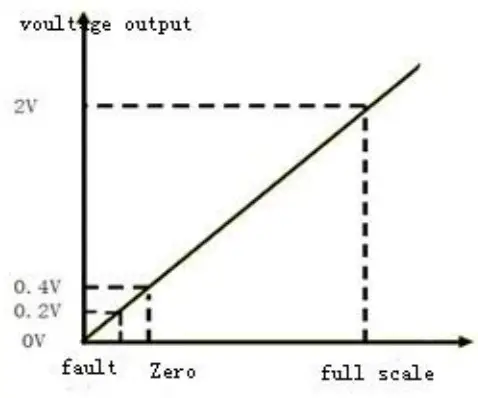
Digital Output
Please referMH-410D communication protocol.
Intrinsically safe explosion-proof
- This product meets the standards of GB3836.1-2010 “Explosive Atmosphere Part 1: General Requirements for Equipment” and GB3836.4-2010 “Explosive Atmosphere Part 4: Equipment Protected by Intrinsically Safe “i”” standards ” ; the explosion-proof mark is Exib Ⅱ B T4 Gb, it is suitable for zone 1 and zone 2, contains Class IIA, T1-T3 explosive environment formed by the flammable gas, mixture of steam and air; it has passed the inspection by the National Quality Inspection Center for Explosion-proof Electrical Products and obtained the explosion-proof certificate.
When using, please note the following: - The intrinsically safe power supply must be used to power the sensor, otherwise the explosion-proof performance will be affected.
- It is forbidden to replace the sensor in dangerous places.
- It is forbidden to disassemble or replace the sensor element to avoid affecting the explosion-proof performance.
- It is not allowed to replace components or structures, so as not to affect the explosion-proof performance.
- The installation and wiring of the safety barrier must be carried out in accordance with the safety barrier instruction manual, and the safety barrier must obtain an explosion-proof certificate.
Connection diagram of intrinsically safe explosion-proof system
The on-site installation must comply with the relevant regulations of the GB3836.15 — 2000 “Electrical Equipment for Explosive Gas Environment Part 15: Electrical Installation in Hazardous Locations (Except Coal and Mines).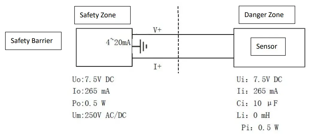
The distribution parameters of the connecting cable between the safety barrier and the sensor should meet:
Cc ≤Co-Ci Lc ≤Lo-Li Ui ≥Uo Ii ≥Io Pi ≥Po
Note:
Uo: Maximum output voltage of safety barrier;
Io: Maximum output current of safety barrier
Po: Maximum output power of safety barrier
Co: Maximum external capacitance of safety barrier
Lo: the maximum external inductance of the safety barrier (see the safety barrier instructions for the above parameters book)
Cc: Maximum allowable distributed capacitance of connecting cable
Ui: sensor maximum input voltage
Ii: Maximum sensor input current
Pi: sensor maximum input power
Ci: Maximum internal capacitance of the sensor
Li: Maximum internal inductance of the sensor
Lc: Maximum allowable distributed inductance of connecting cable
Note:
- The sensor should be calibrated regularly, and the recommended calibration period is 6 months.
- Do not use the sensor for a long time in an environment with high dust density.
- Please use the sensor within the power supply range of the sensor.
- It is forbidden to cut or weld the sensor pins.
Zhengzhou Winsen Electronics Technology Co., Ltd
Add: No.299, Jinsuo Road, National Hi-Tech Zone,
Zhengzhou 450001 China
Tel: +86-371-67169097/67169670
Fax: +86-371-60932988
E-mail: [email protected]
Website: www.winsen-sensor.com
Tel: 86-371-67169097/67169670
Fax: 86-371-60932988
Email: [email protected]
Leading gas sensing solutions supplier in China!
Zhengzhou Winsen Electronics Technology Co., Ltd


