Bauer 1721C-B Portable Clamping Work Station Owner’s Manual
IMPORTANT SAFETY INFORMATION
Set up Precautions
- Set up only according to these instructions. Improper set up can create hazards. Unfold all parts completely and engage all locks before use.
- Wear ANSI-approved safety goggles and heavy-duty work gloves during set up.
- Keep work area clean and well lit.
- Keep bystanders out of the area during set up.
- Do not set up when tired or when under the influence of alcohol, drugs or medication.
- Weight capacity and other product capabilities apply to properly and completely set up product only.
Use Precautions
- Do not stand or sit on Work Station.
- This product is not a toy. Do not allow children to play with or near this item.
- Use as intended only.
- Inspect before every use; do not use if parts are loose or damaged.
- Do not exceed listed weight capacity, centered above Work Station. Be aware of dynamic loading! Sudden load movement may briefly create excess load causing product failure.
- Wear ANSI-approved safety goggles and heavy-duty work gloves during use.
- Use on hard, flat surface that is capable of supporting weight of Work Station and workpiece.
- Maintain product labels and nameplates. These carry important safety information. If unreadable or missing, contact Harbor Freight Tools for a replacement.
- The warnings, precautions, and instructions discussed in this instruction manual cannot cover all possible conditions and situations that may occur. It must be understood by the operator that common sense and caution are factors which cannot be built into this product, but must be supplied by the operator.
Functions
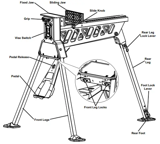
Setup and Operation Instructions
Read the ENTIRE IMPORTANT SAFETY INFORMATION section at the beginning of this document including all text under subheadings therein before set up or use of this product.
Setup
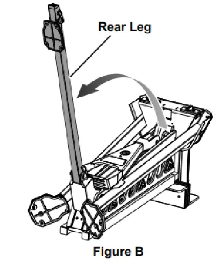
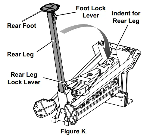
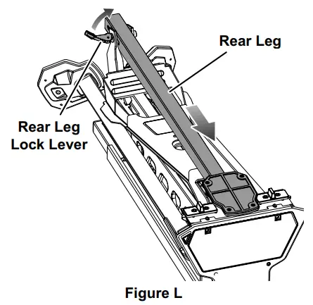
- Swing Rear Leg Lock Lever open and slide Rear Leg back to disengage it from the front of the Work Station

- Swing Rear Leg outwards as far as possible.

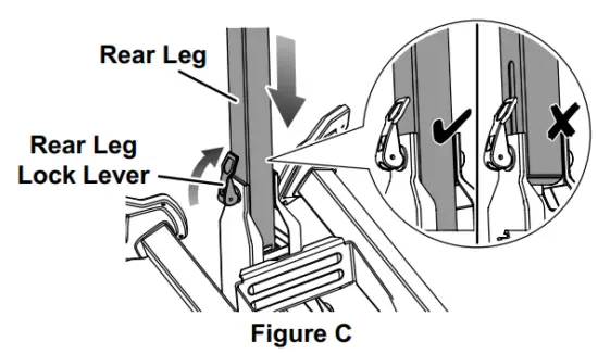
- Slide the Rear Leg up fully so that the slot in its side is not exposed, then swing the Rear Leg Lock Lever closed

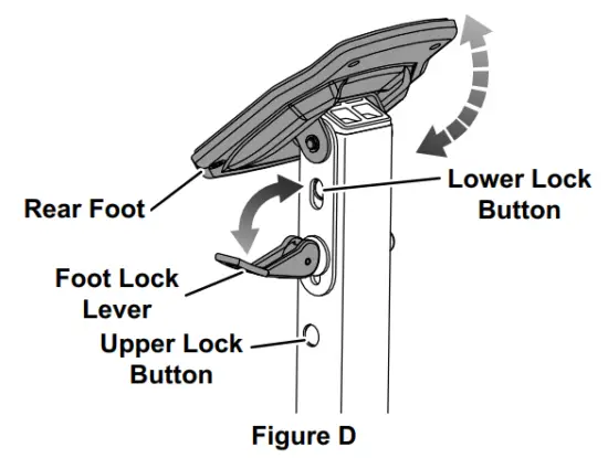
- Swing the Foot Lock Lever open. Unfold the Rear Foot into its operational position and make sure that the Upper and Lower Lock Buttons lock into place. Then, swing the Foot Lock Lever closed.

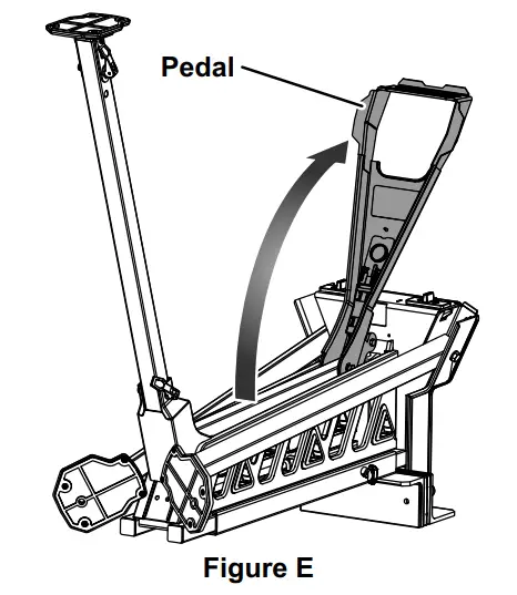
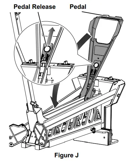
- Swing the Pedal open.

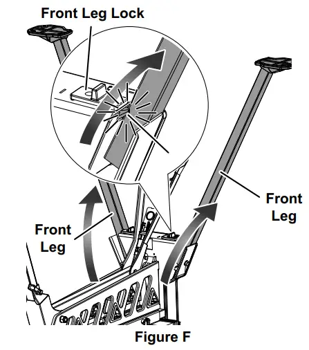
- Pull one of the Front Leg Locks inward, and swing the nearby Front Leg out fully. Release the Front Leg Lock and make sure that it locks in place behind the extended Front Leg. Repeat for the other Front Leg Lock and Front Leg.

- Turn the Work Station upright on a flat, hard, stable surface. Check that all locks are fully engaged and all folding parts are unfolded completely.
Operation
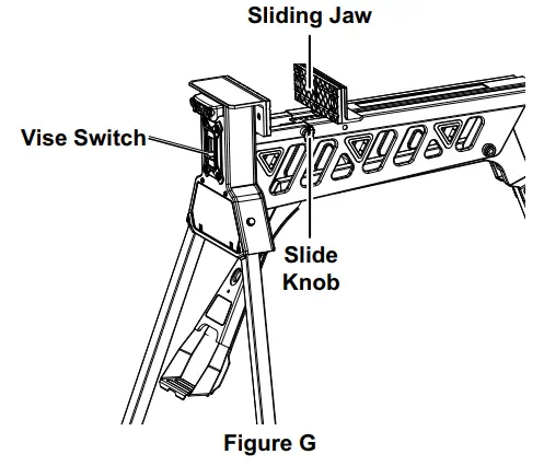
- Loosen the Slide Knob, slide the Vise Switch up to the unlock position, and push the Sliding Jaw open.

Note: For working with very large workpieces, slide the Sliding Jaw back off the end of the Work Station, turn it 180 degrees, and reinstall it. - Place the workpiece between the Jaws with its center of gravity centered above the center of the Work Station.
- Slide the Sliding Jaw up against the workpiece.
- Slide the Vise Switch down to the lock position.
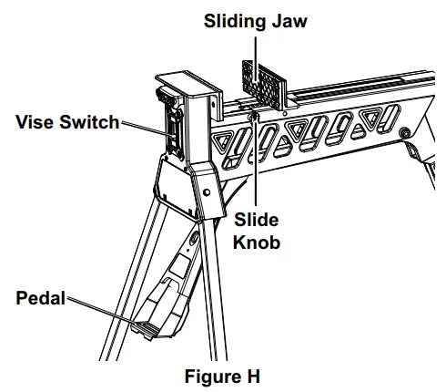
- Step on the Pedal repeatedly to secure the workpiece.
WARNING! To prevent serious injury and product damage, do not jump on the pedal. - To release the workpiece:
a. Slide the Vise Switch up to the unlock position.
b. Step down slightly on the Pedal and then allow it to rise, releasing pressure on the workpiece
After Use
- Slide the Vise Switch up to the unlock position and slide the Sliding Jaw closed. Step down slightly on the Pedal and then allow it to rise, releasing pressure. Tighten the Slide Knob.

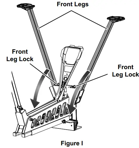
- Turn the Work Station over. Press one of the Front Leg Locks inward and fold the nearby Front Leg up against the Work Station. Repeat for the other Front Leg Lock and Front Leg.

- Pull the Pedal Release out and swing the Pedal up against the Work Station.

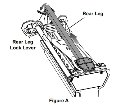
- Swing the Foot Lock Lever open and fold the Rear Foot against the Rear Leg. Swing the Rear Leg Lock Lever open and fold the Rear Leg against the Work Station, aligning it with the indent shown in the illustration.

- Slide the Rear Leg up into the indent and swing the Rear Leg Lock Lever closed to secure it.

Maintenance
Warning
TO PREVENT SERIOUS INJURY FROM TOOL FAILURE: Do not use damaged equipment. If abnormal noise or unexpected movement occurs, have the problem corrected before further use.
- BEFORE EACH USE, inspect the general condition of the tool. Check for:
- loose hardware or housing,
- misalignment or binding of moving parts,
- cracked or broken parts, and
- any other condition that may affect its safe operation.
- If clamp does not move smoothly, lubricate under the Sliding Jaw using general purpose grease.
PLEASE READ THE FOLLOWING CAREFULLY
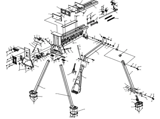
THE MANUFACTURER AND/OR DISTRIBUTOR HAS PROVIDED THE PARTS LIST AND ASSEMBLY DIAGRAM IN THIS DOCUMENT AS A REFERENCE TOOL ONLY. NEITHER THE MANUFACTURER OR DISTRIBUTOR MAKES ANY REPRESENTATION OR WARRANTY OF ANY KIND TO THE BUYER THAT HE OR SHE IS QUALIFIED TO MAKE ANY REPAIRS TO THE PRODUCT, OR THAT HE OR SHE IS QUALIFIED TO REPLACE ANY PARTS OF THE PRODUCT. IN FACT, THE MANUFACTURER AND/OR DISTRIBUTOR EXPRESSLY STATES THAT ALL REPAIRS AND PARTS REPLACEMENTS SHOULD BE UNDERTAKEN BY CERTIFIED AND LICENSED TECHNICIANS, AND NOT BY THE BUYER. THE BUYER ASSUMES ALL RISK AND LIABILITY ARISING OUT OF HIS OR HER REPAIRS TO THE ORIGINAL PRODUCT OR REPLACEMENT PARTS THERETO, OR ARISING OUT OF HIS OR HER INSTALLATION OF REPLACEMENT PARTS THERETO.
Specifications
- Weight Capacity: 600 lb, centered above Work Station
Parts List and Diagram
| Part | Description | Qty |
| 1 | Cap Screw | 1 |
| 2 | Pawl | 1 |
| 3 | Fixing Seat Asm. | 1 |
| 4 | Round Pin | 1 |
| 5 | Cylinder Compression Spring | 3 |
| 6 | Spring Seat | 1 |
| 7 | Limited Rod Asm. | 1 |
| 8 | Cross-Shaped Bolt | 3 |
| 9 | Retaining Plate | 1 |
| 10 | Flat Washer 4 | 20 |
| 11 | Fixing Seat For Limited Rod | 1 |
| 12 | Locknut M4 | 3 |
| 13 | Sliding Rail Asm. | 1 |
| 14 | Steel Ball | 6 |
| 15 | Steel Ball Spring (A) | 2 |
| 16 | Pipe End Cap | 2 |
| 17 | Spacer Rubber Sheet (B) | 1 |
| 18 | Spacer Rubber Sheet (C) | 1 |
| 19 | Hex Socket Screw M6 X 10 | 2 |
| 20 | Flat Washer 6 | 4 |
| 21 | Spacer Rubber Sheet (A) | 1 |
| 22 | Cross Screw M4 X 8 | 15 |
| 23 | Inner Cover Plate | 1 |
| 24 | Locking Knob | 1 |
| 25 | Main Body Asm. | 1 |
| 26 | Hex Bolt M8 X 48 | 2 |
| 27 | Flat Washer 8 | 4 |
| 28 | Locknut M8 | 2 |
| 29 | Hex Bolt M6 X 16 | 2 |
| 30 | Locknut M6 | 4 |
| 31 | Braking Block | 1 |
| 32 | Poly Washer | 2 |
| 33 | Round Pin | 1 |
| 34 | Braking Rocking Handle | 1 |
| 35 | Big Flat Washer 4 | 1 |
| 36 | Tension Spring (C) | 1 |
| 37 | Pressure Spring | 1 |
| 38 | Sliding Pin | 1 |
| 39 | Cross Screw M4 X 8 | 10 |
| 40 | Handle | 1 |
| 41 | Plunger Piston | 2 |
| 42 | Cross Screw M4 X 30 | 2 |
| 43 | Cross Screw M4 X 8 | 2 |
| 44 | Cover Plate | 1 |
| 45 | Lock Button | 1 |
| 46 | Cushion Block | 2 |
| 47 | Tooth Washer | 2 |
| 48 | Faceplate | 1 |
| 49 | Cross Screw M4 X 25 | 2 |
| 50 | Cross Screw M10 X 50 | 2 |
| 51 | Brake Box Cover | 1 |
| 52 | Control Board | 1 |
| 53 | Brake Box | 1 |
| 54 | Indicator (Left) | 1 |
| 55 | Check Block (Left) | 1 |
| 56 | Push Button | 2 |
| 57 | Hex Socket Screw M5 X 10 | 4 |
| 58 | Indicator (Right) | 1 |
| 59 | Pressure Spring | 2 |
| 60 | Hex Socket Screw M4×34 | 2 |
| 61 | Check Block (Right) | 1 |
| 62 | Front Leg Asm. (Left) | 1 |
| 63 | Front Foot Pad (Left) | 1 |
| 64 | Front Foot Pad (Right) | 1 |
| 65 | Front Leg Asm. (Right) | 1 |
| 66 | Lock Button Asm. | 1 |
| 67 | Tension Spring (B) | 2 |
| 68 | Rivet 3×8 | 1 |
| 69 | Pedal Asm. | 1 |
| 70 | Hex Bolt M6 X 30 | 1 |
| 71 | Hex Bolt M8 X 36 | 1 |
| 72 | Braking Rod | 1 |
| 73 | Bolt | 1 |
| 74 | Locating Pad | 1 |
| 75 | Crank Arm Asm. | 1 |
| 76 | Bolt | 1 |
| 77 | Flat Washer | 2 |
| 78 | Rotating Shaft Sleeve | 2 |
| 79 | Retainer Ring | 2 |
| 80 | Rotating Shaft | 1 |
| 81 | Locknut | 1 |
| 82 | Guard | 2 |
| 83 | Flat End Cap Screw M5 X 6 | 1 |
| 84 | Upper Pad | 1 |
| 85 | Tension Spring (A) | 2 |
| 86 | Big Flat Washer 6 | 2 |
| 87 | Pin (A) | 1 |
| 88 | Spring Pin | 2 |
| 89 | Clamping Handle | 2 |
| 90 | Rear Leg | 1 |
| 91 | Split Washer | 2 |
| 92 | Reinforced Plate Asm. | 2 |
| 93 | Pin (B) | 1 |
| 94 | Lower Pad | 1 |
| 95 | Rear Footing Asm. | 1 |
| 96 | Rear Foot Pad | 1 |
| 97 | Thin Hex Locknut M8 | 1 |
For technical questions, please call 1-888-866-5797.
Limited 90 Day Warranty
Harbor Freight Tools Co. makes every effort to assure that its products meet high quality and durability standards, and warrants to the original purchaser that this product is free from defects in materials and workmanship for the period of 90 days from the date of purchase. This warranty does not apply to damage due directly or indirectly, to misuse, abuse, negligence or accidents, repairs or alterations outside our facilities, criminal activity, improper installation, normal wear and tear, or to lack of maintenance. We shall in no event be liable for death, injuries to persons or property, or for incidental, contingent, special or consequential damages arising from the use of our product. Some states do not allow the exclusion or limitation of incidental or consequential damages, so the above limitation of exclusion may not apply to you. THIS WARRANTY IS EXPRESSLY IN LIEU OF ALL OTHER WARRANTIES, EXPRESS OR IMPLIED, INCLUDING THE WARRANTIES OF MERCHANTABILITY AND FITNESS.
To take advantage of this warranty, the product or part must be returned to us with transportation charges prepaid. Proof of purchase date and an explanation of the complaint must accompany the merchandise. If our inspection verifies the defect, we will either repair or replace the product at our election or we may elect to refund the purchase price if we cannot readily and quickly provide you with a replacement. We will return repaired products at our expense, but if we determine there is no defect, or that the defect resulted from causes not within the scope of our warranty, then you must bear the cost of returning the product.
This warranty gives you specific legal rights and you may also have other rights which vary from state to state.
Record Serial Number Here:
Note: If product has no serial number, record month and year of purchase instead.
Note: Some parts are listed and shown for illustration purposes only, and are not available individually as replacement parts. Specify UPC 193175432636 when ordering parts.
26541 Agoura Road • Calabasas, CA 91302 • 1-888-866-5797
Visit our website at: http://www.harborfreight.com
Email our technical support at: [email protected]
When unpacking, make sure that the product is intact and undamaged. If any parts are missing or broken, please call 1-888-866-5797 as soon as possible.
Copyright© 2021 by Harbor Freight Tools®. All rights reserved.
No portion of this manual or any artwork contained herein may be reproduced in any shape or form without the express written consent of Harbor Freight Tools. Diagrams within this manual may not be drawn proportionally. Due to continuing improvements, actual product may differ slightly from the product described herein. Tools required for assembly and service may not be included.


