WISI OL 42 0008 Basic Fiber Multiswitch for 8 resp. 16 Subscriber Instruction Manual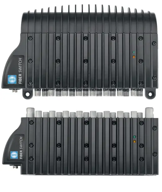
Description
- Multi switch with optical input
- Integrated back conversion of the optical signal into IF
- Upgradeable to 2, 3 or 4 satellite + TV / Radio
- All units operate with only one power supply
- Space-saving design
- 8 or 16 participants output
Installation
Single satellite
- Ensure enough clearance and ventilation in the area the base unit will be fixed
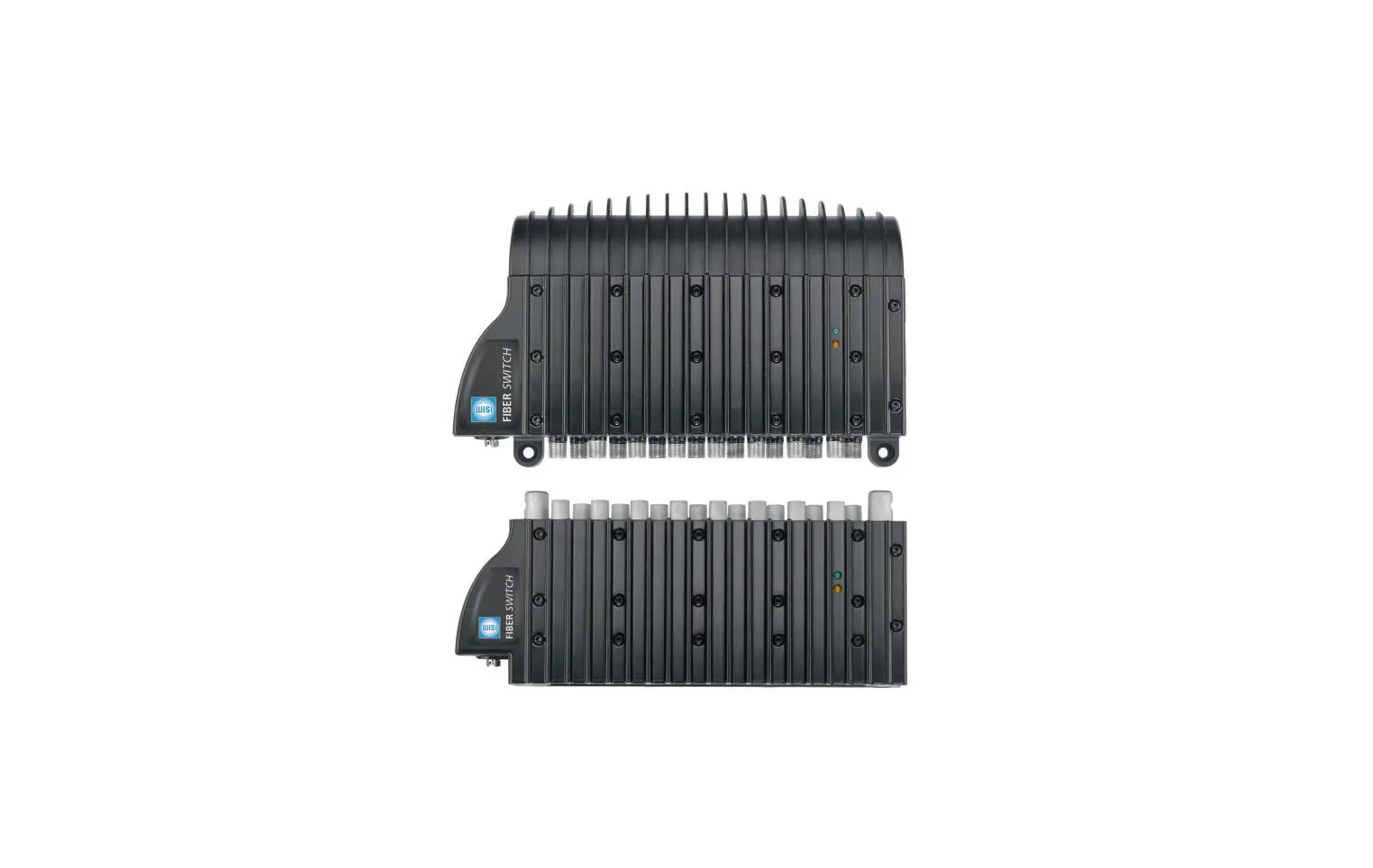
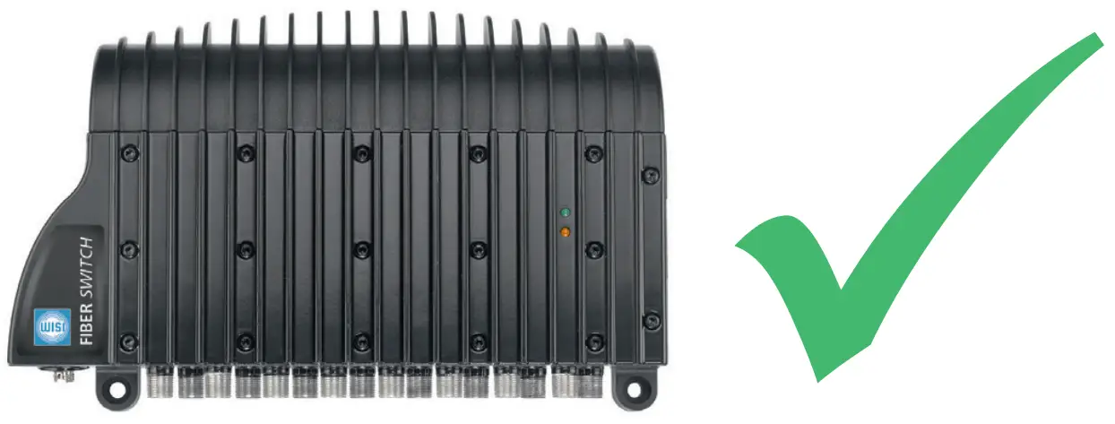
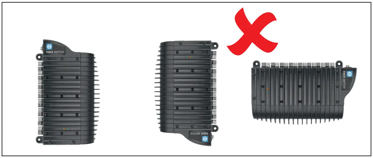
- Unit must be fixed horizontally with F connecters facing down (pic. 1)
- Remove the top plastic cover and attach the base unit to the wall using the 4 screw holes provided
- Replace the top plastic cover
- Connect all required coaxial cables (subscriber outputs)
- Clean (by using OL 57 xxxx) and connect the fiber cable from your PON (passive optical network) to the optical FC/PC connector of the base unit
- Connect the power supply to the DC jack on the base unit
- Use the earthing terminal to ground the base unit
- Power on the unit
Multi satellite installation
- Ensure enough clearance and ventilation in the area the base unit and extension unit will be fixed
- Remove the top plastic cover. Then remove the L bracket attached to the top of the base unit (pic. 2)
- Base unit must be fixed horizontally with F connectors facing down (pic. 1)
- Attach the base unit to the wall using the screw holes provided
- Push the extension unit onto base unit as shown in pic. 3 ensuring the extension unit is fully inserted onto the base unit
- Add any additional extension unit up to maximum of three
- Attach the L bracket to the top of the last extension unit and fix to the wall (pic. 4)
- Replace top plastic cover
- Connect all required coaxial cables (subscriber outputs)
- Clean (by using OL 57 xxxx) and connect the fiber cables from the PON (passive optical network) to the optical FC/PC connectors of all units
- Connect the power supply to the DC jack on the base unit
- Use the earthing terminal to ground the base unit
- Power on the units
Pic. 2 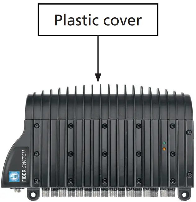
Pic. 3 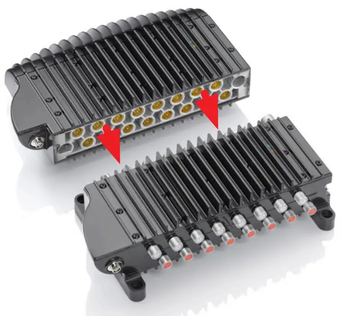
Pic. 4 
LED’s
- Orange LED lights:
Indication of RF output signal - Green LED lights:
Indication that the unit it powered - Orange LED flash:
Device is in boot mode
Technical Data
| Type | OL 41 0008 / OL 42 0008 | OL 41 0016 / OL 42 0016 |
| Wavelength | 1100…1650nm | |
| Optical input power | -14…3 dBm | |
| Number of subscriber | 8 | 16 |
| Output frequency SAT | 950…2150 MHz | |
| Output frequency TERR | 470…790 MHz | |
| Output frequency DAB | 174…240 MHz | |
| Output frequency FM | 88…108 MHz | |
| Output level SAT | 80 dBµV | |
| Output level TERR | 70 dBµV | |
| Supply voltage | 11…20 V DC | |
| Current consumption max. @ 4 satellites | < 1,2 A | |
| Dimension 1 satellite | 227 mm x 138 mm x 67,5 mm | |
| Dimension 2 satellites | 227 mm x 220 mm x 67,5 mm | |
| Dimension 3 satellites | 227 mm x 303 mm x 67,5 mm | |
| Dimension 4 satellites | 227 mm x 385 mm x 67,5 mm | |
Environmental Protection
Waste electrical products should not be disposed of with household waste. Please recycle where facilities exist. Check with your Local Authority or retailer for recycling
PRN: WEE/JA0115XU PCS: B2B Compliance Ltd
WISI Communications GmbH & Co. KG
Empfangs- und Verteiltechnik
Wilhelm-Sihn-Strasse 5-7
75223 Niefern-Öschelbronn
Germany
Inland: Phone +49 7233-66-0 Fax -320
Export: Phone +49 7233-66-0 Fax -320
Email: [email protected]