![]()
ROBIN® LEDBeam 150 RGBA
ROBIN® LEDBeam 150Q RGBA ROBE Innovative Technology
USER MANUAL
Version 1.6
ROBIN LEDBeam 150 RGBA
ROBIN LEDBeam 150Q RGBA
FOR YOUR OWN SAFETY, PLEASE READ THIS USER MANUAL CAREFULLY BEFORE POWERING OR INSTALLING YOUR ROBIN LEDBeam 150 !
Save it for future reference.
This device has left our premises in absolutely perfect condition. In order to maintain this condition and to ensure a safe operation, it is absolutely necessary for the user to follow the safety instructions and warning notes written in this manual. The manufacturer will not accept liability for any resulting damages caused by the non-observance of this manual or any unauthorized modification to the device. Please consider that damages caused by manual modifications to the device are not subject to a warranty.
The ROBIN LEDBeam 150 was designed for indoor use and it is intended for professional application only. It is not for household use.
Safety instructions
DANGEROUS VOLTAGE CONSTITUTING A RISK OF ELECTRIC SHOCK IS PRESENT WITHIN THIS UNIT!
Make sure that the available voltage is not higher than stated on the rear panel of the fixture.
This fixture should be operated only from the type of power source indicated on the marking label. If you are not sure of the type of power supplied, consult your authorized distributor or local power company. Always disconnect the fixture from AC power before cleaning, removing or installing any part of the fixture.
The power plug has to be accessible after installing the fixture. Do not overload wall outlets and extension cords as this can result in fire or electric shock.
Do not allow anything to rest on the power cord. Do not locate this fixture where the cord may be damaged by persons walking on it.
Make sure that the power cord is never crimped or damaged by sharp edges. Check the fixture and the power cord from time to time.
Refer servicing to qualified service personnel.
This fixture falls under protection class I. Therefore this fixture has to be connected to a main socket outlet with a protective earthing connection.
Do not connect this fixture to a dimmer pack.
LED light emission. Risk of eye injury. Do not look into the beam at a short distance of the of the product.
Do not view the light output with optical instruments or any device that may concentrate the beam.
The light source contains blue LEDs.
If the fixture has been exposed to drastic temperature fluctuation (e.g. after transportation), do not switch it on immediately. The arising condensation water might damage your device. Leave the device switched off until it has reached room temperature.
Avoid brute force when installing or operating the fixture.
This fixture was designed for indoor use only, do not expose this unit to rain or use it near water.
When choosing the installation spot, please make sure that the fixture is not exposed to extreme heat, moisture or dust.
Do not block the lens array with any object when the fixture is under operation.
The cooling openings in the head and base of the fixture should never be covered with cloth or other materials, and never must be blocked.
This fixture should not be placed in a built-in installation unless proper ventilation is provided.
Only operate the fixture after having checked that the housing is firmly closed and all screws are tightly fastened.
Always use a secondary safety wire for overhead installation of the fixture.
Make sure that the area below the installation place is blocked when rigging, derigging or servicing the fixture.
The fixture becomes hot during operation. Allow the fixture to cool approximately 15 minutes prior to manipulating it.
Operate the fixture only after having familiarized it with its functions. Do not permit operation by persons not qualified for operating the fixture. Most damages are the result of unprofessional operation! Please use the original packaging if the fixture is to be transported.
Please consider that unauthorized modifications to the fixture are forbidden due to safety reasons!
If this device will be operated in any way different to the one described in this manual, the product may suffer damages and the guarantee becomes void. Furthermore, any other operation may lead to dangers like short-circuit, burns, electric shock, crash, etc.
The potential foggy front lens array does not influence the function of the fixture and does not subject to complaint.
To avoid damage of an internal optical system of the fixture, never let the sunlight (or another light source) light directly to the lens array, even when the fixture is not working Potential color non-uniformity of the front lens array may occur, it does not influence color output from the fixture and is not considered a fault.
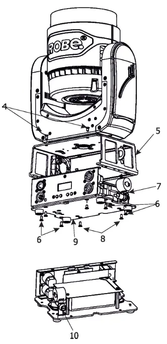
Fixture exterior view
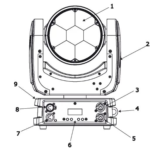
- Moving head
- Attachment point for safety cable
- Base
- Lens array
- Yoke
- Mains IN
- Attachment point for a safety wire
- Mains OUT
- Control panel
- DMX IN
- DMX OUT
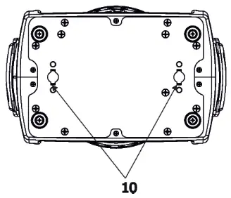
- Base
- Slots for mounting bracket omega CL
Installation
 Fixtures must be installed by a qualified electrician in accordance with all national and local electrical and construction codes and regulations.
3.1 Connection to the mains
For protection from electric shock, the fixture must be earthed!
The ROBIN LEDBeam 150 is equipped with an auto-switching power supply that automatically adjusts to any 5060Hz AC power source from 100-240 Volts.
If you install a cord cap on the power cable to allow connection to power outlets, install a grounding-type (earthed) plug, following the plug manufacturer’s instructions.
If you have any doubts about proper installation, consult a qualified electrician.
| Core (EU) | Core (US) | Connection | Plug Terminal Marking |
| Brown | Black | Live | L |
| Light blue | White | Neutral | N |
| Yellow/Green | Green | Earth |
The device falls under class one and must be earthed (grounded)!
The design of the ROBIN LEDBeam 150 allows connecting of several fixtures to AC mains power in one interconnected daisy chain using power input and throughput connectors. Needed daisy chain cords are stated in the chapter “Technical specifications “
The max. number of connected fixtures depend on the AC mains power voltage:
| CE: | ETL: |
| 15 fixtures at power supply = 230V | 9 fixtures at power supply = 230V |
| 13 fixtures at power supply = 208V | 8 fixtures at power supply = 208V |
| 7 fixtures at power supply = 120V | 4 fixtures at power supply = 120V |
Actual numbers of fixtures may differ from the values stated above as you have to take into account the length of supply cables, circuit breaker etc. at projecting of the installation of the fixtures Do not overload the supply line and the connecting leads.
Do not overload the supply line and the connecting leads.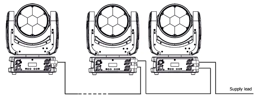
Wiring and connection work must be carried out by qualified staff!
3.2 Rigging the fixture
The installation of the fixture has to be built and constructed in a way that it can hold 10 times the weight for 1 hour without any harming deformation.
The installation must always be secured with a secondary safety attachment, e.g. an appropriate catch net.
This secondary safety attachment must be constructed in a way that no part of the installation can fall down if the main attachment fails.
When rigging, derigging or servicing the fixture staying in the area below the installation place, on bridges, under high working places and other endangered areas is forbidden.
The operator has to make sure that safety-relating and machine-technical installations are approved by an expert before taking into operation for the first time and after changes before taking into operation another time. The operator has to make sure that safety-relating and machine-technical installations are approved by an expert after every four year in the course of an acceptance test. The operator has to make sure that safety-relating and machine-technical installations are approved by a skilled person once a year.
The fixture should be installed outside areas where persons may walk by or be seated.
IMPORTANT! OVERHEAD RIGGING REQUIRES EXTENSIVE EXPERIENCE, including (but not limited to) calculating working load limits, installation material being used, and periodic safety inspection of all installation material and the projector. If you lack these qualifications, do not attempt the installation yourself, but instead use a professional structural rigger. Improper installation can result in bodily injury or damage to property. The fixture has to be installed out of the reach of people.
If the fixture shall be lowered from the ceiling or high joists, professional trussing systems have to be used. The fixture must never be fixed swinging freely in the room.
Caution: Fixture may cause severe injuries when crashing down! If you have doubts concerning the safety of a possible installation, do not install the moving head!
Before rigging make sure that the installation area can hold a minimum point load of 10 times the fixture’s weight.
When installing the device, make sure there is no highly inflammable material (decoration articles, etc.) in a distance of min. 0.4 m.
CAUTION! Use an appropriate clamp to rig the fixture on the truss. Follow the instructions mentioned at the bottom of the base. Make sure that the device is fixed properly! Ensure that the structure (truss) to which you are attaching the fixtures is secure.
The fixture can be placed directly on the stage floor or rigged on a truss without altering its operation characteristics. For securing the fixture to the truss, install a safety wire which can hold at least 10 times the weight of the fixture. Use only the safety wire with a snap hook with a screw lock gate. Fasten the safety cable in the attachment point and around the truss as shown on the picture below.
Rigging via omega bracket: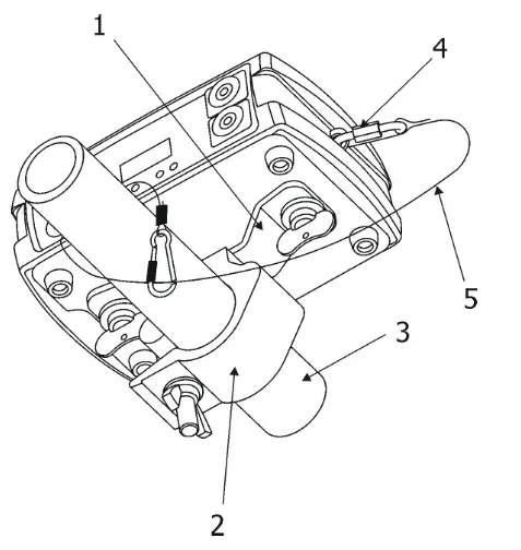
- Omega bracket
- Clamp
- Truss
- Attachment point
- Safety chain
When installing fixtures side-by-side, avoid illuminating one fixture with another!
3.3 Eggcrate installation
Disconnect the fixture from the mains before installing the egg crate.
Screw the egg-crate (1) on the lens array module via the three screws (2).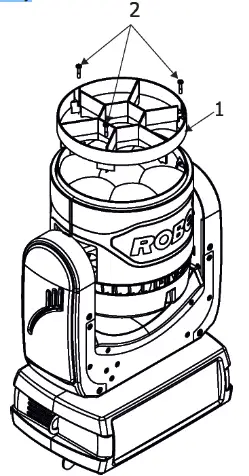
3.4 Diffuser 2° installation
Disconnect the fixture from the mains before installing the diffuser.
- Unscrew three screws (1) from the fixture head and remove the plastic lens (2).
- Place the diffuser 2° (3) to the fixture head, glossy side towards LEDs (correctly aim apertures (4) for screws).
- Screw the diffuser 2° (3) back to the head by means of the three screws (1)
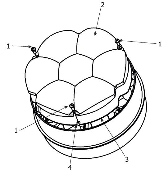
Warning
Installation of the Diffuser 2° is a one-time matter as the screws (1) are screwed into the plastic.
You cannot install and uninstall the Diffuser 2° several times.
3.5 DMX-512 connection
The fixture is equipped with 5-pin XLR sockets for DMX input and output. Only use a shielded twisted-pair cable designed for RS-485 and 5-pin XLR-plugs and connectors in order to connect the controller with the fixture or one fixture with another.
DMX output
XLR socket:
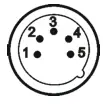
- Shield
- Signal (-)
- Signal (+)
- Used for wireless DMX
- Used for wireless DMX
DMX input
XLR plug:
- Shield
- Signal (-)
- Signal (+)
- Used for wireless DMX
- Used for wireless DMX
If you are using the standard DMX controllers, you can connect the DMX output of the controller directly with the DMX input of the first fixture in the DMX chain. If you wish to connect DMX controllers with other XLR outputs, you need to use adapter cables.
Building a serial DMX chain:
Connect the DMX output of the first fixture in the DMX chain with the DMX input of the next fixture. Always connect one output with the input of the next fixture until all fixtures are connected. Up to 32 fixtures can be interconnected.
Caution: At the last fixture, the DMX-cable has to be terminated with a terminator. Solder a 120 Ω resistor between Signal (–) and Signal (+) into a 5-pin XLR-plug and plug it in the DMX output of the last fixture.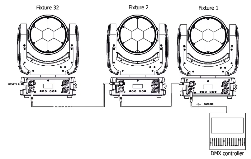
3.6 Wireless DMX operation
The external ROBE Wireless CRMX Dongle allows receiving wireless DMX. This device is equipped with the Lumen Radio CRMX module and antenna for receiving DMX signal. CRMX module operates on the 2.4 GHz band.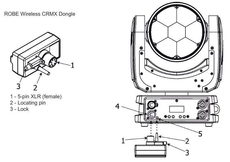
Push in the 5-pin XLR plug (1) into the 5-pin XLR socket (4) and simultaneously locate pin (2) into the hole (5) in the fixture. In this way the wireless DMX module is connected with the fixture.
NOTE: When you disconnect the DMX wireless module from the fixture, press and hold lock (5) during getting the wireless module out.
To link the fixture with the DMX transmitter.
The fixture can be only linked with the transmitter by running the link procedure at the DMX transmitter.
After linking, the level of DMX signal ( 0-100 %) is displayed in the menu item “Stat“ (Special –>Vireless –>Stat).
To unlink the fixture from the DMX transmitter.
The fixture can be unlinked from the receiver via the menu item “ Unlink“ (Special–>Vireless –>Unlink.).
Default settings=Bold print
| Level 1 | Level 2 | Level 3 | Level 4 | Level 5 | Level 6 | Level 7 |
| DMXA | Set DMXA | 001-512 | ||||
| DMX Pres | Mode 1 | |||||
| Mode 2 | ||||||
| Info | POn Time | Total | ||||
| Reset | ||||||
| DMX In | Pan | 0-255 | ||||
| : | ||||||
| Dimm F | 0-255 | |||||
| Hea Temp | Current | |||||
| Highest | ||||||
| High Res | ||||||
| Sw Ver | IC-1 | |||||
| IC-2 | ||||||
| IC-3 | ||||||
| Pers | ||||||
| DMX Pres | Mode 1 | |||||
| Mode 2 | ||||||
| Pan Rev | On, Off | |||||
| Tilt Rev | On, Off | |||||
| P/T Mode | Speed | |||||
| Time | ||||||
| P/T Feed | On, Off | |||||
| Display | Turn | |||||
| On/Off T | On, Off | |||||
| Contrast | 0-100% | |||||
| Backlight | 0-100% | |||||
| BLC DMC | On, Off | |||||
| BLC P/T | On, Off | |||||
| Mic Sens | 0…10…19 | |||||
| Fans | Auto, High,Quiet | |||||
| C Mix M | RGBA, CMY | |||||
| White P | On, Off | |||||
| Dimmer C | Square, Linear | |||||
| LED Freq | Stand | |||||
| High | ||||||
| LED Fadj | -06,-05..00..05, 06 | |||||
| Temp Uni | °C, °F | |||||
| I Ef Pos | Pan | |||||
| : | ||||||
| Dim F | ||||||
| Store | ||||||
| Defaults | ||||||
| Manual | Pan | 0-255 | ||||
| : | ||||||
| Dimm F | 0-255 | |||||
| Test Prg | Static | Pan | 0-255 | |||
| Tilt | 0-255 | |||||
| Run | ||||||
| Dynamic |
| Level 1 | Level 2 | Level 3 | Level 4 | Level 5 | Level 6 | Level 7 |
| Sta Alone | Music T | On, Off | ||||
| Auto Run | Off | |||||
| Test | ||||||
| Prog 1 | ||||||
| Prog 2 | ||||||
| Prog 3 | ||||||
| Pr Play | Test Prg | |||||
| Prog 1 | ||||||
| Prog 2 | ||||||
| Prog 3 | ||||||
| Pr Edit | Prog 1 | Step 1 | Pan | |||
| Prog 2 | : | : | ||||
| Prog 3 | Step 40 | F.Tim | 0-25.5 | |||
| S.Tim | 0-25.5 | |||||
| COPY | ||||||
| Prg End | 1-40 | |||||
| Reset | ||||||
| Special | RDM Low | |||||
| RDM Hight | ||||||
| Wireless | Stat | |||||
| Unlink | ||||||
| Adjust | DMX Val | Pan | 0-255 | |||
| : | ||||||
| Dimm F | 0-255 | |||||
| Clalib | Cal Mech | Pan C | 0-255 | |||
| Tilt C | 0-255 | |||||
| Zoom C | 0-255 | |||||
| Store | ||||||
| Cal Col | Red C | 0-255 | ||||
| Gre C | 0-255 | |||||
| Blu C | 0-255 | |||||
| Amb. C | 0-255 | |||||
| Store | ||||||
| Cal Load | ||||||
| Sw Upd | On, Off |
The ROBIN LEDBeam 150 is equipped with a 2-row LCD display which allows to set the fixture´s behavior according to your needs, obtain information on its operation, test its various parts and lastly program it, if it has to be used in a stand-alone mode.
Control panel: [ESCAPE] button used to leave the menu without saving changes. [NEXT] , [PREV] buttons for moving between menu items and for value adjusting.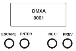
[ENTER] button used to enter the selected menu (menu item) and to confirm the adjusted value.
After switching the fixture on, the display shows the current DMX address.
5.1 Addressing (DMXA)
Set DMXA- Use this menu item to set the DMX start address of the fixture, which is defined as the first channel from which the ROBIN LEDBeam 150 will respond to the controller. If you set, for example, the address 23, the ROBIN LEDBeam 150 will use channels 23 – 44 for control (if Mode 1 is selected).
Please, be sure that you do not have any overlapping channels in order to control each ROBIN LEDBeam 150 correctly and independently from any other fixture on the DMX data link. If there is no data received at the DMX input, the display will start to flash “0001” with the actually stored DMX address. DMX Pres – DMX preset. Use the menu to select desired channel mode.
Mode 1 – 22 control channels (default)
Mode 2 – 16 control channels
5.2 Fixture information (Info)
POn Time – Power-on time. Select this menu to read the number of fixture operation hours.
Total – The item shows the total number of operating hours since the ROBIN LEDBeam 150 has been fabricated.
Reset – The item shows the number of operating hours that the
ROBIN LEDBeam 150 has been powered on since the counter was last reset.
In order to reset this counter to 0, press and hold both [NEXT] and [PREV] buttons and the [Enter] button at the same time.
DMX In – DMX readout. The menu is used to read the DMX values of each channel received by the fixture.
Hea Temp – Head Temperature. The menu shows the temperature on the LED module.
Current – A current temperature of the LED module.
Highest – A maximum temperature of the LED module since the fixture has been fabricated.
High Res – A maximum temperature of the LED module since the counter was last reset.
In order to reset this counter, press and hold both [NEXT] and [PREV] buttons and the [Enter] button at the same time.
Sw Ver – Software versions. Select this item to read the software version of the fixture modules.
IC-1 – A pan/Tilt processor.
IC-2 – A display processor.
IC-3 – LED control processor.
5.3 Personality (Pers)
DMX Pres – DMX preset. Use the menu to select desired channel mode.
Mode 1 – 22 control channels
Mode 2 – 16 control channels
Pan Rev – Pan reverse. The item allows inverting pan movement.
Tilt Rev – Tilt reverse. The item allows inverting tilt movement.
P/T Mode – Pan and Tilt movement mode. Use this menu to set the mode of the pan/tilt movement.
Speed – Both Pan and tilt will move with the same speed as adjusted at channel 5
“Pan/Tilt speed, Pan/Tilt time”.
Time – The pan and tilt will move at different speeds and they will come at the same time to the end point of their tracks (pan and tilt use their optimal speeds).
The time of the pan/tilt movement (25.5 sec. max.) is set by the channel “Pan/Tilt speed, Pan/Tilt time”.
P/T Feed – Pan and Tilt Feedback. The menu item allows returning the mowing head to the required pan/tilt position after changing the position by an external force if this option is set on.
Note. The Pan/Tilt Feedback should be permanent On, the option Off is not suitable for standard operation and the head of the fixture can be damaged!
Display – Display adjusting. This menu allows you to adjust the display behavior.
Turn – This function turns the display by 180°.
On/Off T – This function allows you to keep the display permanently on or turn it off two minutes after last pressing any button on the control panel.
Contrast- Use this function to adjust the contrast of the display (0-100%).
Backlight- Use this function to adjust the backlight of the display (0-100%).
BLC DMC – Blackout during movement correction. Set this option on if you wish to close light output during the time when the head goes to its correct position, which has been changed by an external force.
BLC P/T – Active blackout. The menu item allows closing light output while the pan/tilt DMX values are changing.
C Mix M – Colour mixing mode. This item allows switching into RGBA or CMY mode. In the CMY mode, the Amber(8bit)/Amber (16) bit channels are not active.
White P – White Point 8000K. If the function is on, the CTC channel allows setting desired white in range of 8000K-2700K
(0 DMX=8000K, 255 DMX=2700K). A necessary condition is , that RGBA channels have to be set at the same DMX values, e.g. 255.
If this function is off, the range of whites is not uniform and may be different for each fixture.
Mic Sens – Microfon sensitivity. Enter the menu if you want to adjust the microphone sensitivity ( 1-max., 19-min.).
Fans – Fans mode. Use the menu to set the fixture fans to the max. power (“High”) ,auto-control mode (“Auto”) and quiet mode (“Quiet”).
Dimmer C – Dimmer curve. Use the menu to select the desired dimmer curve.
Linear – a linear curve.
Square – a square law curve.
LED Freq – LEDs frequency setup. The function allows you to set the PWM (Pulse Width Modulation) output frequency of LEDs to Standard or High.
Stand – a standard frequency (300Hz), the default setting.
High – a high frequency (600Hz)
LED Fadj – LEDs frequency fine adjustment. The function allows you to change the selected PWM output frequency of LEDs in 6 levels up and down around the selected frequency in the menu “LED Freq”.
-06…-01 – Frequence levels 1-6 under selected frequency.
00 – Selected frequency (Standard or High)
01…06 – Frequency levels 1-6 above selected frequency.
Temp Uni – Temperature unit. Use the menu item to change the temperature unit from °C to °F.
I Ef Pos – Init effect positions. Use the menu to set all effects to the desired positions at which they will stay after switching the fixture on without DMX signal connected.
Defaults – The menu item allows to set all fixture parameters to the default (factory) values.
5.4 Manual Control (Manual)
Use the menu to control all fixture channels by means of the control panel.
5.5 Test program (Test Prg)
Use this menu to to run a special demo-test sequence without an external controller, which will show you some possibilities of using ROBIN LEDBeam 150.
Static – Static mode. This mode is suitable for projections on the wall, ceiling or ground without any head movement.
Dynamic – Dynamic mode. This mode uses all ROBIN LEDBeam 150 functions including pan/tilt movement and therefore is good for a complete introduction of the fixture.
5.6 Stand-alone (St Alone)
Music T – Music trigger. Select this function to enable the sound control of the running program via the built-in microphone.
Auto Run – Presetting playback. This function allows you to select the program which will be played in the stand-alone mode after switching the fixture on. Selected program will be played continuously in a loop.
Off – The option disables „Auto Run” function.
Test – The option will start built-in test program.
Prog 1 – The option will start user-created program 1
Prog 2 – The option will start user-created program 2
Prog 3 – The option will start user-created program 3
Pr Play – Playing program. Select this menu to run a user-created program in a loop.
Test Prg – The option runs built-in test program.
Prog 1 – The option runs user-created program 1
Prog 2 – The option runs user-created program 2
Prog 3 – The option runs user-created program 3 Select the program you wish and press [ENTER]. The selected program starts running. By Pressing [ENTER] again, program pauses running.
Pr Edit – Editing program. Select this menu to edit or create the program. The ROBIN LEDBeam 150 has one built-in program and one user-editable program up to 40 steps. Each program step has a step time, during which effects last in the current step, and a fade time, during which effects move to new positions.
To edit the program:
- Press [NEXT] or [PREV] to select the menu ” Pr Edit” and press [ENTER].
- Press [NEXT] or [PREV] to select the desired program step and press the [ENTER] button.
- Press [NEXT] or [PREV] to select the desired item and press the [ENTER] button. Now you can edit by [NEXT] or [PREV] buttons the DMX value (0-255) for selected item:
| Prg End. | a total number of the program steps (value 1-40). This value you should be set before starting of programming (e.g. if you want to create program with the 10 steps, set Prg End=10). |
| PAn | a coarse pan movement |
| PAn F | a fine pan movement |
| Tilt | a coarse tilt movement |
| Tilt F | a fine tilt movement |
| P/T Sp | a pan/tilt speed |
| Powr | power/special functions |
| Virt C | a virtual colour wheel |
| Red | a red colour coarse |
| Red F | a red colour fine |
| Green | a green colour coarse |
| Green F | a green colour fine |
| Blue | a blue colour coarse |
| Blue F | a blue colour fine |
| Amber | an amber colour |
| Amber F | an amber colour fine |
| CTC | a colour temperature correction |
| C Mix C | a colour mix control |
| Zoom | a zoom function |
| Zoom F | a zoom function fine |
| Stro | a strobe/shutter function |
| Dimm | a dimmer function coarse |
| Dim F | a dimmer function fine |
| F.Tim | a fade time (0-25.5 sec) |
| S.Tim | a step time (0-25.5 sec) |
| COPY | copying the current prog. step to |
4. Press the [ENTER] button to confirm the adjusted value.
5. Press the [ESCAPE] button, and select next prog. step, press the [ENTER] button and repeat steps 3 – 5).
5.7 Reset
This option enables the ROBIN LEDBeam 150 to index all effects and return to their standard positions.
5.8 Special functions (Special)
RDM Low – This menu item shows the first part of the RDM identification code.
RDM High – This menu item shows the second part of the RDM identification code.
Wireless – Wireless DMX information. The menu allows to read some information about Wireless DMX operation Stat
– Wireless status. Use the menu to read wireless DMX status.
Unlink – use this item to unlink fixture from wireless DMX.
Adjust – Adjustment. The menu allows the fine adjustment of effects.
DMX Val- DMX values. Use the menu to set DMX values of fixture´s channels.
Calib – calibration of white colour.
Cal Mech – Use this menu to calibrate pan/tilt/zoom position.
Cal Col – Use this menu to set the white color 5600K.
Calibration of the pan/tilt/zoom via the control board
- Disconnect DMX controller from the fixture and enter the “Cal Mech” menu.
- Use the [PREV] and [NEXT] to find “Pan C” and press [ENTER].
- Set desired value and save it by pressing [ENTER].
- Repeat steps 2 and 3 for “Tilt C” and “Zoom C”.
- After calibrating both effects, find item “Store” and press [ENTER]. to save all adjusted values and reset the fixture.
Calibration of the white 5600K via the control board
- Disconnect the DMX controller from the fixture, set the shutter, dimmer and RGBA channels at 255 DMX, zoom at 128 DMX and the CTC channel at DMX=64 (white 5600K). Aim the light beam on the lux meter (e.g. Minolta CL-500 A Chroma meter) which is placed about 5 m from the fixture.
- Set the menu items Colour Mix Mode to RGBA and “White Point 8000K to On (Pers-> C Mix M -> RGBA, Pers-> White P -> On).
- Enter the menu “Cal Col”.
- By means of the “Red C, Gre C, Blu C and Amb C” items adjust the 5600K color temperature as exactly as possible (∆u´v´= 0).
- After adjusting 5600K color temperature, select item Store and press the [ENTER] button to save all adjusted values.
Note: you can also use DMX controller for both calibrations stated above, calibration protocol is the following:
| Effect | Mode 1 | Mode 2 |
| Pan-fine adjustment | channel 23 | channel 17 |
| Tilt – fine adjustment | channel 24 | channel 18 |
| Zoom -fine adjustment | channel 25 | channel 19 |
| Red – red saturation | channel 26 | channel 20 |
| Green- green saturation | channel 27 | channel 21 |
| Blue – blue saturation | channel 28 | channel 22 |
| Amber – amber saturation | channel 29 | channel 23 |
Cal Load – Loads default (factory) calibration.
Sw Upd – Software update. The menu item allows you to update software in the fixture.
The following items are required in order to update software:
– PC running Windows or Linux or macOS
– DSU file
– Flash cable RS232/DMX, P/N13050624 (if you want to use a serial port of PC)
– Robe Universal Interface or Robe Universal interface WTX (if you want to use a USB port of PC) After the software updates the fixture will be set to default (factory) values.
To update software in the fixture:
- DSU file is available from the Robe website at WWW.robe.cz.
File with extension zip is intended for Windows (used and tested from XP to W10 on 32/64bit systems).
File with extension tbz is intended for Linux (used and tested on Debian and Ubuntu 32/64bit).
File with extension dmg is intended for macOS (used and tested on OSX up to Sierra) XQuartz is required, install it from https://www.xquartz.org/
Save the download file to a folder on your computer.
In case you use windows, extract files in the zip file (e.g. DSU_RobinLedBeam150_18041738.zip) - Disconnect the fixture from the DMX controller.
- If you use the flash cable RS232/DMX, connect a serial port of your computer with DMX input of the fixture by means of the cable.
If you use the Robe Universal Interface, connect a USB port of your computer with the Robe Universal Interface by means of the USB cable and DMX input of the fixture with the DMX output of the Robe Universal Interface via a DMX cable. - Switch the fixture to the update mode (Special –> SW Upd).
Note: If you do not want to continue in the software update, you have to switch off and on the fixture to escape from the updating mode.
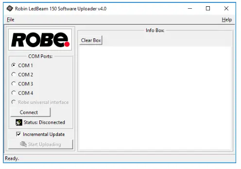
We recommend canceling all running programs on your computer before starting the software update. - Double-click the software uploader file (e.g. DSU_RobinLedBeam150_18041738.exe) in the extracted files. The Software Uploader program will start running.

- Select the correct “COM ” number if you use a Flash cable RS232/DMX or select “Robe Universal Interface 1 ” if you use the Robe Universal Interface/Robe Universal Interface WTX and then click on the “Connect” button.
- If the connection is OK, click the “Start Uploading” button to start software uploading. It will take several minutes to perform a software update.
If the option “Incremental Update” is not checked, all processors will be updated (including processors with the same software version).
If you wish to update only processors with new version of the software, check the “Incremental Update box“.
Avoid interrupting the process. Update status is being displayed in the “Info Box” window.
When the update is finished, the line with the text “Fixture is successfully updated“ will appear in this window.
In case upload process is interrupted (e.g. power loss), the fixture stays in “Updating mode” and you will have to repeat the software update again.
Another way, how to update software in the fixtures (especially large installation of fixtures) is to use the ROBE Uploader. It is software for an automatized software update of Robe fixtures. It takes advantage of RDM support).
For more information please see https://www.robe.cz/robe-uploader/.
RDM
This fixture supports RDM operation. RDM (Remote Device Management) is a bi-directional communications protocol for use in DMX512 control systems, it is the new open standard for DMX512 device configuration and status monitoring.
The RDM protocol allows data packets to be inserted into a DMX512 data stream without adversely affecting existing non-RDM equipment. By using a special „Start Code,“ and by complying with the timing specifications for DMX512, the RDM protocol allows a console or dedicated RDM controller to send commands to and receive messages from specific moving lights. RDM allows explicit commands to be sent to a device and responses to be received from it. The list of commands for ROBIN LEDBeam 150 is the following.
| Parameter ID | Discovery command | SET command | GET command |
| DISC_UNIQUE_BRANCH | * | ||
| DISC_MUTE | * | ||
| DISC_UN_MUTE | * | ||
| DEVICE_INFO | * | ||
| SUPPORTED_PARAMETERS | * | ||
| SOFTWARE_VERSION_LABEL | * | ||
| DMX_START_ADDRESS | * | * | |
| IDENTIFY_DEVICE | * | * | |
| DEVICE_MODEL_DESCRIPTION | * | ||
| MANUFACTURER_LABEL | * | ||
| DEVICE_LABEL | * | * | |
| SENSOR_DEFINITION | * | ||
| SENSOR_VALUE | * | ||
| DISPLAY_INVERT | * | * | |
| DISPLAY_LEVEL | * | * | |
| PAN_INVERT | * | * | |
| TILT_INVERT | * | * | |
| DEVICE_RESET | * | ||
| DMX_PERSONALITY | * | * | |
| DMX_PERSONALITY_DESCRIPTION | * | ||
| STATUS_MESSAGES | * | ||
| STATUS_ID_DESCRIPTION | * | ||
| DEVICE_HOURS | * |
| PARAMETER_DESCRIPTION | * | ||
| ROBE_DMX_INPUT | * | * | |
| ROBE_WIRELESS_UNLINK | * |
Error and information messages
Short Err
The message informs you that short circuit has occurred on the LED PCB.
Tilt Err
This message will appear after the reset of the fixture if the head´s magnetic-indexing circuit malfunctions (sensor failed or magnet is missing) or the stepping motor is defective or its driving IC on the PCB. The head is not located in the default position after the reset.
Technical Specifications
| Electrical | Power supply:…………………….electronic auto-ranging Input voltage range:…………… supply 100-240V, 50-60Hz Fuse:…………………………………T 3.15A Max. power consumption ……..220W (power factor=0.97, I=0.98A at 230V) Mains input: CE – max. 16A ETL – max. 10A Mains output: CE – max. 15A ETL – max. 9A |
| Optic | Light source: 7 x high power RGBA multichip LEDs Min LED life expectancy: 20.000 hours RGBA/CMY colour mixing Variable CTO 2700K-8000K Halogen lamp effect at whites 2700K and 3200K |
| Virtual colour wheel | 66 preset colours Rainbow effect with with variable speed |
| Zoom range | 3.8°-60° |
| Strobe | Strobe effect with variable speed (0.3 – 20Hz) Random strobe pulse-effect with variable speed Opening/closing pulse effect with variable speed |
| Dimmer | Smooth dimmer from 0 – 100 % |
| Pan/Tilt | Max. pan movement range: 450° Max. tilt movement range: 228° 16 bit movement resolution Automatic Pan/Tilt position correction Remotely controllable speed of pan/tilt movement for easy programming |
| Control | 2-row LCD display & 4 buttons Readout fixture usage, receiving DMX values, temperatures, etc Built-in analyzer for easy fault finding, error messages Built-in demo sequences Silent fans cooling, Stand-alone operation 3 user editable programs, each up to 40 steps Supported protocols: USITT DMX 512, RDM, Support of RDM (Remote Device Management) 2 DMX modes (22, 16 control channels) |
| External Wireless DMX/RDM module (optional) | Compliance with USITT DMX-512 (1986 & 1990) and 512-A Full DMX fidelity and frame integrity Auto sensing of DMX frame rate and frame size<5ms DMX latency Operational frequency range of 2402-2480 MHz Producer: LumenRadio |
| Connection | DMX data in/out: Locking 5-pin XLR AC power input: Chassis connector Neutrik PowerCon, A-type, NAC3MPA AC power output: Chassis connector Neutrik PowerCon, B-type, NAC3MPB |
| Rigging | Mounting points: pair of 1/4-turn locks Mounting horizontally or vertically via Omega bracket |
| Temperatures | Maximum ambient temperature : 45° C Maximum housing temperature : 80° C |
| Distances | Min. distance from flammable surfaces: 0.4 m Min. distance of illuminated objects: 0.8 m |
| Total heat dissipation | 750 BTU/h (calculated) |
| Weight: | 5.7 kg |
| Dimensions (mm) | 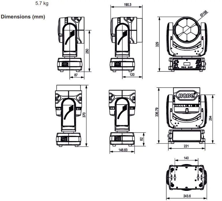 |
| Accessories | 1x Mounting bracket Omega CL assembled (P/N 99010420) |
| Optional accessories | (P/N 10980127) ROBE Wireless CRMX Dongle (P/N1305 1731) Mains Cable PowerCon In/open ended, 2m (P/N 1305 1724) Mains Cable PowerCon In/Schuko, 2m (P/N 1305 1725) Mains Cable PowerCon In/CEE 16A, 2m (P/N 1305 1726) Mains Cable PowerCon In/US, 2m (P/N 1305 1727) Daisy Chain PowerCon In/Out, EU, 2m (P/N 1305 1728 ) Daisy Chain PowerCon In/Out, US, 2m (P/N 10980346 ) EggCrate for Robin LEDBeam 150 (P/N 10980445) EggCrate for Robin LEDBeam 150, ParFect 150 white (P/N 10980496) EggCrate for Robin LEDBeam 150 RAL9003 glossy (P/N 10980423) Diffuser 2° for Robin LEDBeam 150 (P/N 17030386) Doughty Trigger Clamp (P/N 99011963) Safety wire 35 kg |
Maintenance and cleaning
It is absolutely essential that the fixture is kept clean and that dust, dirt and smoke-fluid residues must not build up on or within the fixture. Otherwise, the fixture‘s light output will be significantly reduced. Regular cleaning will not only ensure the maximum light output, but will also allow the fixture to function reliably throughout its life. A soft lint-free cloth moistened with any weak detergent solution is recommended for cleaning fixture´s covers, under no circumstances should alcohol or solvents be used!
DANGER!
Disconnect from the mains before starting any maintenance and cleaning work
The interior of the fixture should be cleaned at least annually using a vacuum cleaner or compressed air.
The cooling fans should be cleaned at least twice a year.
Important! Never use alcohols (ethanol, methanol, isopropyl alcohol), acetone, and other aggressive solvent for cleaning the front lens array.
Recommended steps for cleaning the front lens array:
- Use low-pressure compressed air to remove coarse dust from lenses.
- Use distilled water with a weak detergent solution and a lint-free small cloth for further cleaning of lenses.
- Use an antistatic, alcohol-free screen cleaner (we recommend the Lyreco Screen Cleaner) and polish lenses until they are dry.
- Check the lenses are dry before reapplying power.
Note: potential foggy front lens array does not influence the function of the fixture and does not subject to complaint More complicated maintenance and service operations are only to be carried out by authorized distributors.
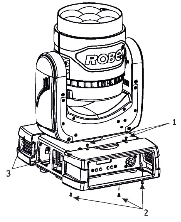
9.1 Replacing fuse
- Replace the fuse by a fuse of the same type and rating only.
Before replacing the fuse, unplug mains lead!
- Remove the plastic covers of the base (3) by unscrewing 5 fastening screws (1) and (2) on each cover.
- Unscrew four screws (4) on the top chassis (5). Lay down the fixture and unscrew four screws (6) on the bottom plate (9) to push out inside module of the base.
- Unscrew two screws (8) on the bottom plate to remove rear panel of the fixture (7).

- Now you have access for the fuse holder (10) in the inside module of the base.
- Remove the old fuse from the fuse holder.
- Install the new fuse into the fuse holder.
- Assemble the base of the fixture.
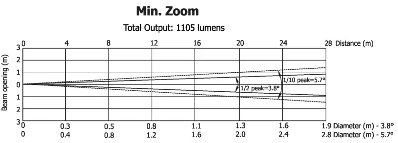
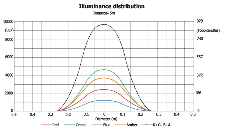
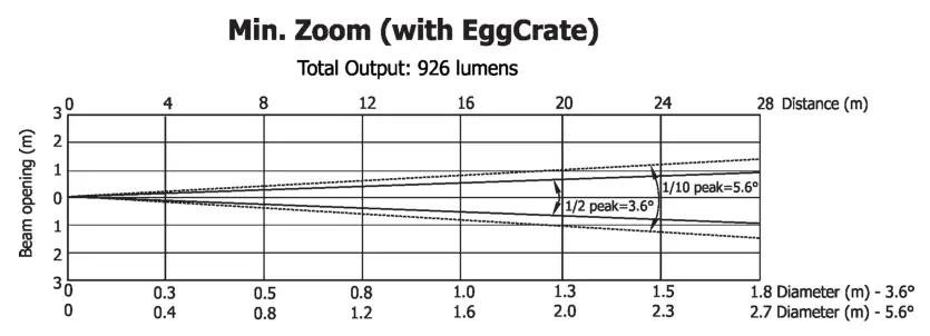
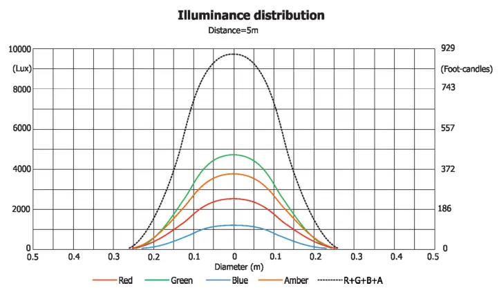
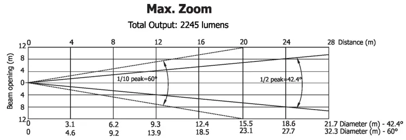
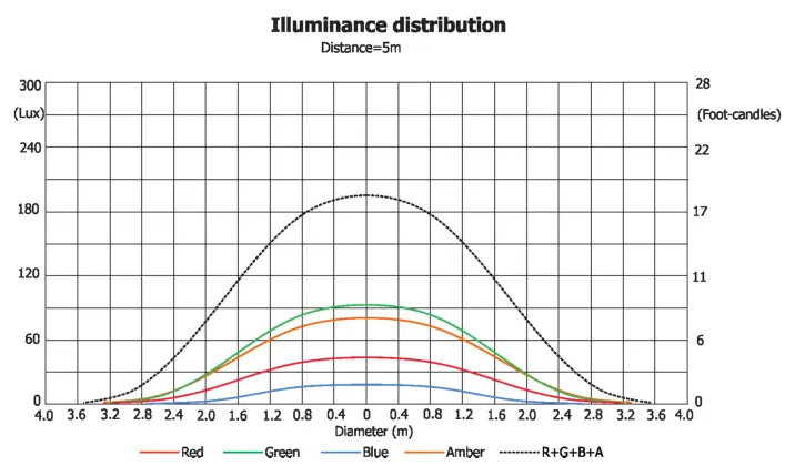
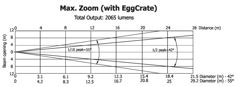
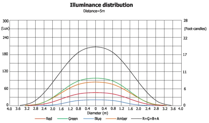
Photometric diagrams
| Distance (m) | 4 | 5 | 8 | 12 | 16 | 20 | 24 | 28 | |
| Red | 3670/341 | 2350/218 | 918/85 | 408/38 | 230/21 | 147/14 | 102/10 | 75/7 | Intensity (center) Lux/Footcandles |
| Green | 7547/701 | 4830/449 | 1887/175 | 838/78 | 472/44 | 300/28 | 210/20 | 154/14 | |
| Blue | 1140/106 | 1140/106 | 445/41 | 198/18 | 111/10 | 71/7 | 50/5 | 36/3.4 | |
| Amber | 6015/559 | 3850/358 | 1504/140 | 668/62 | 376/35 | 240/22 | 167/16 | 123/11.4 | |
| R+G+B+A | 15328/1424 | 9810/911 | 3832/356 | 1703/158 | 960/89 | 613/57 | 426/40 | 313/29 |
| Distance (rn) | 4 | 5 | 8 | 12 | 16 | 20 | 24 | 28 | |
| Red | 3633/338 | 2325/216 | 908/84 | 404/38 | 227/21 | 145/13.5 | 100/9.4 | 74/7 | i_nlynFZ tithes° |
| Green | 7469/694 | 4780/444 | 1867/174 | 830/77 | 467/43 | 300/28 | 208/19 | 152/14 | |
| Blue | 1764/164 | 1130/105 | 441/41 | 196/18 | 110/10 | 71/7 | 50/4.6 | 36/3 | |
| Amber | 5953/553 | 3810/354 | 1488/138 | 662/62 | 372/35 | 238/22 | 165/15 | 122/11 | |
| R+G+B+A | 15172/1410 | 9710/902 | 3793/352 | 1686/157 | 948/88 | 607/56 | 421/39 | 310/29 |
| Distance (m) | 4 | 5 | 8 | 12 | 16 | 20 | 24 | 28 | |
| Red | 78/7 | 50/5 | 20/2 | 9/0.8 | 5/0.5 | 3/0.3 | 2/0.2 | 1.6/0.1 | Intensity (center) LUX /Footcandles |
| Green | 168/16 | 108/10 | 42/4 | 19/1.7 | 11/1 | 6.8/0.6 | 5/0.4 | 3/0.3 | |
| Blue | 41/4 | 26/2,4 | 10/0.9 | 5/0.4 | 2.5/0.2 | 1.6/0.2 | 1/0.1 | 0.8/0.1 | |
| Amber | 133/12 | 85/8 | 33/3 | 15/1.4 | 8/0.8 | 5/0.5 | 4/0.3 | 3/0.3 | |
| R+G+B+A | 320/30 | 205/19 | 80/7.4 | 36/3 | 20/1.9 | 13/1.2 | 9/0.8 | 7/0.6 |
| Distance (m) | 4 | 5 | 8 | 12 | 16 | 20 | 24 | 28 | |
| Red | 72/6.7 | 46/4 | 18/1.7 | 8/0.7 | 5/0.5 | 3/3.1 | 2/0.2 | 2/0.1 | Intensity (center) LUX /Footcandles |
| Green | 160/15 | 103/9.6 | 40/3.7 | 18/1.7 | 10/0.9 | 7/0.6 | 5/0.4 | 3/0.3 | |
| Blue | 38/3.5 | 24/2.2 | 9/0.9 | 4/0.4 | 2/0.2 | 1.4/0.1 | 1/0.1 | 0.7/0.1 | |
| 125/12 | 80/7.4 | 31/1.3 | 14/1.3 | 8/0.7 | 5/0.5 | 4/0.3 | 3/0.2 | ||
| R+G+B+A | 294/27 | 188/18 | 73/7 | 33/3 | 18/1.7 | 12/1.1 | 8/0.8 | 6/0.6 |
April 1, 2022
Copyright © 2018-2022 Robe Lighting – All rights reserved
All Specifications subject to change without notice
Made in ROBE Lighting s.r.o., Palackého 416, 757 01 Valašské Meziříčí, Czech Republic
DMX protocol
| Robin LEDBeam 150 RGBA/LEDBeam 150Q RGBA/LEDBeam 150 FWQ RGBA/LEDBeam 150 FW RGBA – DMX protocol | ||||
| Version: 1.3 Mode 1-Standard 16-bit, Mode 2 -Reduced 8-bit | ||||
| Mode/channel | DMX Value | Function | Type of control | |
| 1 | 2 | |||
| 1 | 1 | Pan (8 bit) | ||
| 0 – 255 | Pan movement by 450° (128=default) | proportional | ||
| 2 | 2 | Pan Fine (16 bit) | ||
| 0 – 255 | Fine control of pan movement (0=default) | proportional | ||
| 3 | 3 | Tilt (8 bit) | ||
| 0 – 255 | Tilt movement by 228° (128=default) | proportional | ||
| 4 | 4 | Tilt fine (16 bit) | ||
| 0 – 255 | Fine control of tilt movement (0=default) | proportional | ||
| 5 | 5 | Pan/Tilt speed , Pan/Tilt time | ||
| 0 | Standard mode (0=default) | step | ||
| 1 | Max. Speed Mode | step | ||
| Pan/Tilt speed mode | ||||
| 2 – 255 | Speed from max. to min. | proportional | ||
| Pan/Tilt time mode | ||||
| 2 – 255 | Time from 0.2 sec. to 25.5 sec. | proportional | ||
| 6 | 6 | Power/Special functions | ||
| 0 -19 | Reserved (0=default) | |||
| To activate following functions, stop in DMX value for at least 3 s and shutter must be closed at least 3 sec. („Shutter,Strobe” channel 20/15 must be at range: 0-31 DMX). Corresponding menu items are temporarily overriden. | ||||
| 20-24 | Display ON | step | ||
| 25-29 | Display OFF | step | ||
| 30-34 | RGBA colour mixing mode | step | ||
| 35-39 | CMY colour mixing mode | step | ||
| 40-44 | Pan/Tilt speed mode | step | ||
| 45 – 49 | Pan/Tilt time mode | step | ||
| 50 -54 | Blackout while pan/tilt moving | step | ||
| 55 -59 | Disabled blackout while pan/tilt moving | step | ||
| 60 – 64 | Dimmer curve – square law | step | ||
| 65 – 69 | Dimmer curve – linear | step | ||
| 70 – 74 | Fans mode: Auto | step | ||
| 75 – 79 | Fans mode: High | step | ||
| 80-84 | White point 8000K ON | step | ||
| 85-89 | White point 8000K OFF | step | ||
| 90-94 | Fans mode: Quiet | step | ||
| 95 -129 | Reserved | |||
| To activate following functions, stop in DMX value for at least 3 seconds. Corresponding menu items are temporarily overriden. | ||||
| 130 – 139 | Reserved | |||
| 140 – 149 | Pan/Tilt reset | step | ||
| 150 – 159 | Zoom reset | step | ||
| 160 – 169 | Reserved | step | ||
| Tungsten effect simulution for whites 2700K and 3200K | ||||
| 170-171 | Tungsten effect simulation (750W) On | step | ||
| 172-173 | Tungsten effect simulation (1000W) On | step | ||
| Mode/channel | DMX Value | Function | Type of control | |
| 1 | 2 | |||
| 174-175 | Tungsten effect simulation (1200W) On | step | ||
| 176-177 | Tungsten effect simulation (2000W) On | step | ||
| 178-179 | Tungsten effect simulation (2500W) On | step | ||
| 180-181 | Tungsten effect simulation Off | step | ||
| 182-184 | Reserved | |||
| 185 | PWM output frequency of LEDS: Standard (300Hz)** | step | ||
| 186 | PWM output frequency of LEDS: High (600Hz)** | step | ||
| ** You can adjust selected frequency in 6 steps Up or Down around selected frequency – see table below . Default value of PWM frequency set in the fixture is Standard. | ||||
| 187 | LED Frequency (step -6) | step | ||
| 188 | LED Frequency (step -5) | step | ||
| 189 | LED Frequency (step -4) | step | ||
| 190 | LED Frequency (step -3) | step | ||
| 191 | LED Frequency (step -2) | step | ||
| 192 | LED Frequency (step -1) | step | ||
| 193 | LED Frequency (Standard or High) | step | ||
| 194 | LED Frequency (step +1) | step | ||
| 195 | LED Frequency (step +2) | step | ||
| 196 | LED Frequency (step +3) | step | ||
| 197 | LED Frequency (step +4) | step | ||
| 198 | LED Frequency (step +5) | step | ||
| 199 | LED Frequency (step +6) | step | ||
| 200 – 209 | Total fixture reset | step | ||
| 210 – 218 | Reserved | |||
| The following RoboSpot related commands are only applicable when the RoboSpot is connected: | ||||
| 219 – 220 | RoboSpot enabled | step | ||
| 221 – 222 | RoboSpot disabled – except handle faders and pan/tilt | step | ||
| 223 – 224 | RoboSpot fully disabled | step | ||
| 225 – 255 | Reserved | |||
| 7 | 7 | Virtual colour wheel | ||
| 0 | No function (0=default) | step | ||
| 1-2 | Filter 4 (Medium Bastard Amber) | step | ||
| 3-4 | Filter 25 (Sunset Red) | step | ||
| 5-6 | Filter 19 (Fire) | step | ||
| 7-8 | Filter 26 (Bright Red) | step | ||
| 9-10 | Filter 58 (Lavender) | step | ||
| 11-12 | Filter 68 (Sky Blue) | step | ||
| 13-14 | Filter 36 (Medium Pink) | step | ||
| 15-16 | Filter 89 (Moss Green) | step | ||
| 17-18 | Filter 88 (Lime Green) | step | ||
| 19-20 | Filter 90 (Dark Yellow Green) | step | ||
| 21-22 | Filter 49 (Medium Purple) | step | ||
| 23-24 | Filter 52 (Light Lavender) | step | ||
| 25-26 | Filter 102 (Light Amber) | step | ||
| 27-28 | Filter 103 (Straw) | step | ||
| 29-30 | Filter 140 (Summer Blue) | step | ||
| 31-32 | Filter 124 (Dark Green) | step | ||
| 33-34 | Filter 106 (Primary Red) | step | ||
| 35-36 | Filter 111 (Dark Pink) | step | ||
| Mode/channel | DMX Value | Function | Type of control | |
| 1 | 2 | |||
| 37-38 | Filter 115 (Peacock Blue) | step | ||
| 39-40 | Filter 126 (Mauve) | step | ||
| 41-42 | Filter 117 (Steel Blue) | step | ||
| 43-44 | Filter 118 (Light Blue) | step | ||
| 45-46 | Filter 122 (Fern Green) | step | ||
| 47-48 | Filter 182 (Light Red) | step | ||
| 49-50 | Filter 121 (Filter Green) | step | ||
| 51-52 | Filter 128 (Bright Pink) | step | ||
| 53-54 | Filter 131 (Marine Blue) | step | ||
| 55-56 | Filter 132 (Medium Blue) | step | ||
| 57-58 | Filter 134 (Golden Amber) | step | ||
| 59-60 | Filter 135 (Deep Golden Amber) | step | ||
| 61-62 | Filter 136 (Pale Lavender) | step | ||
| 63-64 | Filter 137 (Special Lavender) | step | ||
| 65-66 | Filter 138 (Pale Green) | step | ||
| 67-68 | Filter 798 (Chrysalis Pink) | step | ||
| 69-70 | Filter 141 (Bright Blue) | step | ||
| 71-72 | Filter 147 (Apricot) | step | ||
| 73-74 | Filter 148 (Bright Rose) | step | ||
| 75-76 | Filter 152 (Pale Gold) | step | ||
| 77-78 | Filter 154 (Pale Rose) | step | ||
| 79-80 | Filter 157 (Pink) | step | ||
| 81-82 | Filter 143 (Pale Navy Blue) | step | ||
| 83-84 | Filter 162 (Bastard Amber) | step | ||
| 85-86 | Filter 164 (Flame Red) | step | ||
| 87-88 | Filter 165 (Daylight Blue) | step | ||
| 89-90 | Filter 169 (Lilac Tint) | step | ||
| 91-92 | Filter 170 (Deep Lavender) | step | ||
| 93-94 | Filter 172 (Lagoon Blue) | step | ||
| 95-96 | Filter 194 (Surprise Pink) | step | ||
| 97-98 | Filter 180 (Dark Lavender) | step | ||
| 99-100 | Filter 181 (Congo Blue) | step | ||
| 101-102 | Filter 197 (Alice Blue) | step | ||
| 103-104 | Filter 201 (Full C.T. Blue) | step | ||
| 105-106 | Filter 202 (Half C.T. Blue) | step | ||
| 107-108 | Filter 203 (Quarter C.T. Blue) | step | ||
| 109-110 | Filter 204 (Full C.T. Orange) | step | ||
| 111-112 | Filter 219 (Fluorescent Green) | step | ||
| 113-114 | Filter 206 (Quarter C.T. Orange) | step | ||
| 115-116 | Filter 247 (Filter Minus Green) | step | ||
| 117-118 | Filter 248 (Half Minus Green) | step | ||
| 119-120 | Filter 281 (Three Quarter C.T. Blue) | step | ||
| 121-122 | Filter 285 (Three Quarter C.T. Orange) | step | ||
| 123-124 | Filter 352 (Glacier Blue) | step | ||
| 125-126 | Filter 353 (Lighter Blue) | step | ||
| 127-128 | Filter 507 (Madge) | step | ||
| 129-130 | Filter 778 (Millennium Gold) | step | ||
| 131-132 | Filter 793 (Vanity Fair) | step | ||
| 133-235 | Raw DMX | proportional | ||
| Mode/channel | DMX Value | Function | Type of control | |
| 1 | 2 | |||
| 236-245 | Rainbow effect (with fade time) from slow-> fast | proportional | ||
| 246-255 | Rainbow effect (without fade time) from slow-> fast | proportional | ||
| 8 | 8 | Red/Cyan (8 bit)* | ||
| 0 – 255 | Colour saturation control – coarse 0-100% (255=default) | proportional | ||
| 9 | * | Red/Cyan (16bit)* | ||
| 0 – 255 | Colour saturation control – fine (255=default) | proportional | ||
| 10 | 9 | Green/Magenta (8 bit) * | ||
| 0 – 255 | Colour saturation control – coarse 0-100% (255=default) | proportional | ||
| 11 | * | Green/Magenta (16bit) * | ||
| 0 – 255 | Colour saturation control – fine (255=default) | proportional | ||
| 12 | 10 | Blue/Yellow (8 bit) * | ||
| 0 – 255 | Colour saturation control – coarse 0-100% (255=default) | proportional | ||
| 13 | * | Blue/ Yellow (16bit) * | ||
| 0 – 255 | Colour saturation control – fine (255=default) | proportional | ||
| 14 | 11 | Amber (8 bit) | ||
| If RGBA mode is selected: | ||||
| 0-255 | Colour saturation control – coarse 0-100% (255=default) | proportional | ||
| If CMY mode is selected: | ||||
| 0 – 255 | No function | |||
| 15 | * | Amber (16 bit) | ||
| 0 – 255 | Colour saturation control – fine (255=default) | proportional | ||
| 16 | 12 | CTC | ||
| If function “White Point 8000K” is ON | ||||
| 0-255 | Col. temperature correction from 8000K to 2700K -for whites only | proportional | ||
| (0=8000K, 64=5600K, 128=4200K, 192=3200K, 255=2700K) | ||||
| To get colour temperatures stated above, RGBA channels have to be set at the same value e.g. 255DMX (0=default) | ||||
| (To activate Tungsten effect at 2700K and 3200K , set DMX value at “Power/Special functions” channel) | ||||
| If function “White Point 8000K” is OFF | ||||
| 0-255 | Colour temperature correction for from cool white to 2700K | proportional | ||
| 17 | 13 | Colour Mix control | ||
| Defines relation between colour channels | ||||
| “Virtual” = Virtual Colours (Virtual Colour Wheel) | ||||
| “Colour mix” = Colour channels (RGBA/CMY) | ||||
| 0-9 | Virtual colors (“Virtual” has priority) | step | ||
| 10-19 | Maximum mode (highest values have priority) | step | ||
| 20-29 | Minimum mode (lowest values have priority) | step | ||
| 30-39 | Multiply mode (multiply Virtual and Colour Mix) | step | ||
| 40-49 | Addition mode (Virtual + Colour mix) (45=default) | step | ||
| 50-59 | Subtraction mode (Virtual – Colour mix) | step | ||
| 60-69 | Inverted Subtraction mode (Colour mix – Virtual) | step | ||
| 70-128 | Reserved | |||
| 129 | Virtual colors (virtual has priority) | step | ||
| 130-254 | Crossfade (crossfade between Virtual and Colour mix) | proportional | ||
| 255 | Colour channels (“Colour mix” has priority) | step | ||
| 18 | 14 | Zoom | ||
| 0-255 | Zoom from max. to min.beam angle (128=default) | proportional | ||
| 19 | * | Zoom – fine | ||
| 0-255 | Fine zooming (0=default) | proportional | ||
| Mode/channel | DMX Value | Function | Type of control | |
| 1 | 2 | |||
| 20 | 15 | Shutter/ strobe | ||
| 0 – 31 | Shutter closed | step | ||
| 32 – 63 | Shutter open (32=default) | step | ||
| 64 – 95 | Strobe-effect from slow to fast | proportional | ||
| 96 – 127 | Shutter open | step | ||
| 128 – 143 | Opening pulse in sequences from slow to fast | proportional | ||
| 144 – 159 | Closing pulse in sequences from fast to slow | proportional | ||
| 160 – 191 | Shutter open | step | ||
| 192 – 223 | Random strobe-effect from slow to fast | proportional | ||
| 224 – 255 | Shutter open | step | ||
| 21 | 16 | Dimmer intensity (8 bit) | ||
| 0 – 255 | Dimmer intensity from 0% to 100% (0=default) | proportional | ||
| 22 | * | Dimmer intensity – fine (16 bit) | ||
| 0 – 255 | Fine dimming (0=default) | proportional | ||
| *Select RGA or CMY mixing mode on channel “Power/Special functions” . | ||||
| Copyright ©2018-2022 Robe Lighting s.r.o. – All rights reserved | ||||
| All Specifications subject to change without notice | ||||
| Colours on Virtual Colour Wheel | ||||
| Colour name | Red (DMX) | Green (DMX) | Blue (DMX) | Amber (DMX) |
| Filter 4 (Medium Bastard Amber) | 60 | 141 | 33 | 239 |
| Filter 25 (Sunset Red) | 255 | 9 | 2 | 223 |
| Filter 19 (Fire) | 255 | 0 | 0 | 36 |
| Filter 26 (Bright Red) | 255 | 0 | 0 | 0 |
| Filter 58 (Lavender) | 0 | 47 | 165 | 255 |
| Filter 68 (Sky Blue) | 0 | 250 | 138 | 45 |
| Filter 36 (Medium Pink) | 200 | 78 | 26 | 255 |
| Filter 89 (Moss Green) | 0 | 255 | 0 | 80 |
| Filter 88 (Lime Green) | 122 | 255 | 0 | 103 |
| Filter 90 (Dark Yellow Green) | 2 | 255 | 0 | 0 |
| Filter 49 (Medium Purple) | 255 | 0 | 27 | 0 |
| Filter 52 (Light Lavender) | 176 | 221 | 66 | 255 |
| Filter 102 (Light Amber) | 213 | 255 | 0 | 255 |
| Filter 103 (Straw) | 193 | 255 | 19 | 245 |
| Filter 140 (Summer Blue) | 74 | 255 | 42 | 51 |
| Filter 124 (Dark Green) | 16 | 255 | 4 | 15 |
| Filter 106 (Primary Red) | 255 | 3 | 1 | 0 |
| Filter 111 (Dark Pink) | 255 | 116 | 48 | 255 |
| Filter 115 (Peacock Blue) | 4 | 255 | 37 | 29 |
| Filter 126 (Mauve) | 255 | 0 | 39 | 0 |
| Filter 117 (Steel Blue) | 130 | 255 | 40 | 55 |
| Filter 118 (Light Blue) | 14 | 255 | 78 | 11 |
| Filter 122 (Fern Green) | 3 | 255 | 4 | 102 |
| Filter 182 (Light Red) | 255 | 16 | 2 | 0 |
| Filter 121 (Filter Green) | 143 | 255 | 0 | 0 |
| Filter 128 (Bright Pink) | 255 | 0 | 31 | 103 |
| Filter 131 (Marine Blue) | 14 | 255 | 34 | 81 |
| Filter 132 (Medium Blue) | 7 | 228 | 120 | 0 |
| Filter 134 (Golden Amber) | 164 | 83 | 0 | 0 |
| Filter 135 (Deep Golden Amber) | 255 | 50 | 0 | 0 |
| Filter 136 (Pale Lavender) | 134 | 123 | 30 | 10 |
| Filter 137 (Special Lavender) | 129 | 123 | 40 | 10 |
| Filter 138 (Pale Green) | 186 | 255 | 14 | 32 |
| Filter 798 (Chrysalis Pink) | 49 | 17 | 144 | 32 |
| Filter 141 (Bright Blue) | 0 | 225 | 62 | 0 |
| Filter 147 (Apricot) | 122 | 102 | 5 | 88 |
| Filter 148 (Bright Rose) | 255 | 30 | 13 | 39 |
| Filter 152 (Pale Gold) | 97 | 128 | 11 | 102 |
| Filter 154 (Pale Rose) | 96 | 105 | 11 | 103 |
| Filter 157 (Pink) | 228 | 85 | 18 | 69 |
| Filter 143 (Pale Navy Blue) | 0 | 210 | 75 | 73 |
| Filter 162 (Bastard Amber) | 208 | 252 | 25 | 184 |
| Filter 164 (Flame Red) | 253 | 0 | 0 | 82 |
| Filter 165 (Daylight Blue) | 9 | 255 | 106 | 61 |
| Filter 169 (Lilac Tint) | 159 | 194 | 28 | 71 |
| Filter 170 (Deep Lavender) | 195 | 177 | 78 | 149 |
| Colour name | Red (DMX) | Green (DMX) | Blue (DMX) | Amber (DMX) |
| Filter 172 (Lagoon Blue) | 0 | 255 | 71 | 10 |
| Filter 194 (Surprise Pink) | 109 | 131 | 55 | 92 |
| Filter 180 (Dark Lavender) | 139 | 107 | 126 | 19 |
| Filter 181 (Congo Blue) | 30 | 0 | 255 | 3 |
| Filter 197 (Alice Blue) | 75 | 222 | 156 | 26 |
| Filter 201 (Full C.T. Blue) | 135 | 242 | 64 | 36 |
| Filter 202 (Half C.T. Blue) | 180 | 255 | 48 | 35 |
| Filter 203 (Quarter C.T. Blue) | 172 | 255 | 40 | 74 |
| Filter 204 (Full C.T. Orange) | 196 | 155 | 4 | 103 |
| Filter 219 (Fluorescent Green) | 80 | 155 | 23 | 26 |
| Filter 206 (Quarter C.T. Orange) | 137 | 185 | 18 | 92 |
| Filter 247 (Filter Minus Green) | 122 | 175 | 57 | 245 |
| Filter 248 (Half Minus Green) | 118 | 199 | 41 | 255 |
| Filter 281 (Three Quarter C.T. Blue) | 191 | 255 | 76 | 5 |
| Filter 285 (Three Quarter C.T. Orange) | 210 | 182 | 7 | 29 |
| Filter 352 (Glacier Blue) | 0 | 173 | 55 | 51 |
| Filter 353 (Lighter Blue) | 0 | 222 | 51 | 83 |
| Filter 507 (Madge) | 255 | 0 | 0 | 109 |
| Filter 778 (Millennium Gold) | 190 | 32 | 0 | 143 |
| Filter 793 (Vanity Fair) | 255 | 5 | 26 | 48 |
ROBE(‘) lighting s.r.o.
• Czech Republic • www.robetz


