

Instruction Manual
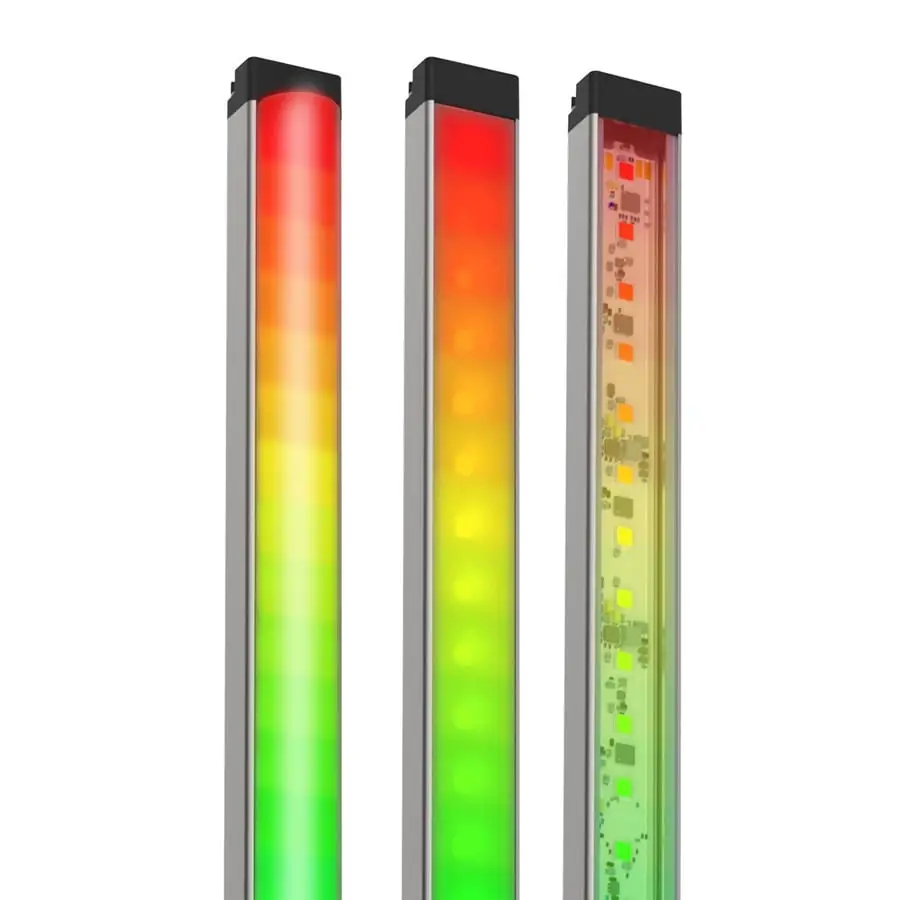
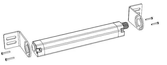
Banner’s WLS28 Pro LED Strip Lights with IO-Link have sturdy aluminum housings, shatterproof windows, and impressive environmental ratings, making them an ideal general-purpose LED light for machine, enclosure, or other industrial lighting applications.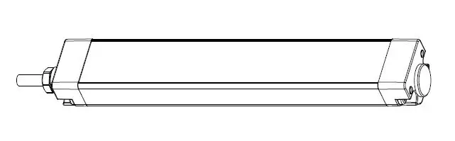
- High quality illumination and indication from RGBW LEDs
- Six white color temperatures for comfort and compatibility
- 13 color options for varied indication and inspection uses
- IO-Link gives full access to individual LED control, color, flashing, intensity, and animation settings, as well as advanced operating modes for displaying distance, count, time, and position
- Available in six lengths from 145 mm to 1130 mm
- Lensed models or choice of clear or diffuse window
Important: Read the following instructions before operating the light. Please download the complete WLS28 Pro LED Strip Light with IO-Link technical documentation, available in multiple languages, from
www.bannerengineering.com for details on the proper use, applications, Warnings, and installation instructions of this device.
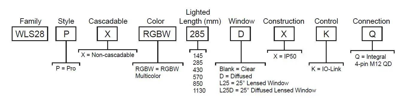
Models
Wiring Diagrams
| Male | Pin | Wire Color | Description | ||
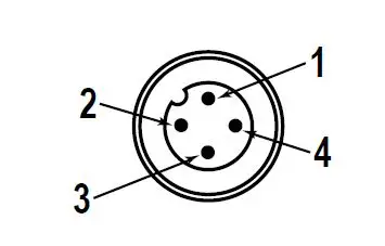 |
| 1 | Brown | 18 V DC to 30 V DC | |
| 2 | White | Not used | |||
| 3 | Blue | DC common | |||
| 4 | Black | IO-Link Communication | |||
IO-Link Process Data Out (Master to Device)
IO-Link® is a point-to-point communication link between a master device and a sensor and/or light. It can be used to automatically parameterize sensors or lights and to transmit process data. For the latest IO-LINK protocol and specifications, please visit www.io-link.com.
For the latest IODD files, please refer to the Banner Engineering Corp website at: www.bannerengineering.com.
Segment Mode
Configure the light to have up to 10 segments which scale in size automatically with the length of the light or select Manual Segment Configuration which allows each segment to have a custom LED width and LED offset from the beginning of each segment to the beginning of the light.
Use process data to set each segment to off, solid on, flash, or animation mode. Use parameter data to change segment number and configuration, color, intensity, flash speed, direction, background, and select animation type.
| Animation | Description |
| Off | Segment is off |
| Steady | Color 1 is solid on at defined intensity |
| Flash | Color 1 flashes at defined speed, color intensity, and pattern (normal, strobe, three pulse, SOS, or random) |
| Two Color Flash | Color 1 and Color 2 flash alternately at defined speed, color intensities, and pattern (normal, strobe, three pulse, SOS, or random) |
| Two Color Shift | Color 1 and Color 2 flash alternately on adjacent LEDs at defined speed and color intensities |
| Ends Steady | Color 1 is solid on in the center of the segment as defined by Percent Width of Color 1 at defined color intensity while Color 2 is solid on for half of the remaining percentage on each end of the segment at defined color intensity |
| Ends Flash | Color 1 is solid on in the center of the segment as defined by Percent Width of Color 1 at defined color intensity while Color 2 flashes on for half of the remaining percentage on each end of the segment at defined speed, color intensity, and pattern (normal, strobe, three pulse, SOS, or random) |
| Scroll | Color 1 fills the segment as defined by Percent Width of Color 1 and moves in one direction up or down against the background of Color 2 at the defined speed, color intensities, style, and direction |
| Center Scroll | Color 1 fills the segment as defined by Percent Width of Color 1 and moves in or out from the center of the segment against the background of Color 2 at the defined speed, color intensities, style, and direction |
| Bounce | Color 1 fills the segment as defined by Percent Width of Color 1 and moves up and down against the background of Color 2 at the defined speed, color intensities, and style |
| Center Bounce | Color 1 fills the segment as defined by Percent Width of Color 1 and moves in and out from the center of the segment against the background of Color 2 at the defined speed, color intensities, and style |
| Intensity Sweep | Color 1 repeatedly increases and decreases intensity between 0% to 100% at defined speed and color intensity |
| Two Color Sweep | Color 1 and Color 2 define the end values of a line across the color gamut. The segment continuously displays a color by moving along the line at the defined speed and color intensities |
| Spectrum | The segment scrolls through the 13 predefined colors with a different color on each LED at the defined speed, Color 1 intensity, and direction |
Run Mode
Use process data to control entire light and select color, intensity, flash, direction, and animations. Use parameter data to create custom colors, intensity, and flash speeds.
| Animation | Description |
| Off | Light is off |
| Steady | Color 1 is solid on at defined intensity |
| Flash | Color 1 flashes at defined speed, color intensity, and pattern (normal, strobe, three pulse, SOS, or random) |
| Two Color Flash | Color 1 and Color 2 flash alternately at defined speed, color intensities, and pattern (normal, strobe, three pulse, SOS, or random) |
| Two Color Shift | Color 1 and Color 2 flash alternately on adjacent LEDs at defined speed and color intensities |
| Ends Steady | Color 1 is solid on in the center of the light as defined by Percent Width of Color 1 at defined color intensity while Color 2 is solid on for half of the remaining percentage on each end of the light at defined color intensity |
| Ends Flash | Color 1 is solid on in the center of the light as defined by Percent Width of Color 1 at defined color intensity while Color 2 flashes on for half of the remaining percentage on each end of the light at defined speed, color intensity, and pattern (normal, strobe, three pulse, SOS, or random) |
| Scroll | Color 1 fills the light as defined by Percent Width of Color 1 and moves in one direction up or down against the background of Color 2 at the defined speed, color intensities, style, and direction |
| Center Scroll | Color 1 fills the light as defined by Percent Width of Color 1 and moves in or out from the center of the light against the background of Color 2 at the defined speed, color intensities, style, and direction |
| Bounce | Color 1 fills the light as defined by Percent Width of Color 1 and moves up and down against the background of Color 2 at the defined speed, color intensities, and style |
| Center Bounce | Color 1 fills the light as defined by Percent Width of Color 1 and moves in and out from the center of the light against the background of Color 2 at the defined speed, color intensities, and style |
| Intensity Sweep | Color 1 repeatedly increases and decreases intensity between 0% to 100% at defined speed and color intensity |
| Two Color Sweep | Color 1 and Color 2 define the end values of a line across the color gamut. The light continuously displays a color by moving along the line at the defined speed and color intensities |
| Spectrum | The light scrolls through the 13 predefined colors with a different color on each LED at the defined speed, Color 1 intensity, and direction |
Level Mode
Use process data to set the level value. Use parameter data to set range, thresholds, colors, intensities, flash speeds, background, and animation types.
| General Settings | Description |
| Level Mode Value | Value of the level of the light (between 0 to 65,535) |
| Full Scale Value | Set the upper limit of the Level Mode Value (between 0 to 65,535) |
| Background Color and Intensity | A defined color and intensity is displayed on LEDs that are not active |
| Dominance | Dominant: The entire light displays the active threshold color Non-Dominant: LEDs displays their defined threshold colors |
| Sub-Segment Style | If Level Mode Value is a partial percentage of an LED, select if segment will be on steady or analog dimmed to the partial percentage |
| Filtering | Smooths the input signal by varying the sample size None: There is no filtering Low: The sample size is short and changes to the input signal are more noticeable High: The sample size is long and changes to the input signal are less noticeable |
| Hysteresis | Determines the signal value change needed to transition between thresholds and to prevent chatter None: The value follows the input signal High: A large value change is needed to transition between thresholds |
| Base and Threshold 1-4 Settings | Description |
| Threshold Type: Base | A defined animation state is displayed on LEDs that are not defined within a threshold |
| Threshold Type: 1-4 | Level Mode Values that conform to Threshold Comparison Type ≤ or ≥ and the Threshold Value Percent are displayed on LEDs as defined by the threshold color, intensity, flash speeds, and run mode animation types |
Dim and Blend Mode
Dim and blend mode uses the light to finely adjust the intensity of one color, or blend between two or three colors. Use process data to set the dim and blend mode value. Use parameter data to set number of colors, range, colors, and intensities.
| General Settings | Description |
| Dim and Blend Mode Value | Value of the intensity of the light in 1 Color mode or value of the blend between colors in 2 and 3 Color mode (between 0 to 65,535) |
| Full Scale Value | Set the upper limit of the Dim and Blend Mode Value (between 0 to 65,535) |
| Number of Colors | 1: Color 1 is solid on at intensity defined by the percentage of Dim and Blend Mode Value to the Full Scale Value when Color 1 Intensity is set to high 2: Color 1 and Color 2 define the end values of a line across the color gamut. The light displays a blended color and moves along the line as defined by the Dim and Blend Mode Value and color intensities 3: Color 1 and Color 2 define the beginning and end value of one line across the color gamut. Color 2 and Color 3 define the beginning and end value of a second line across the color gamut. The light displays a blended color and moves along the two lines as defined by the Dim and Blend Mode Value and color intensities |
| Filtering | Smooths the input signal by varying the sample size None: There is no filtering Low: The sample size is short and changes to the input signal are more noticeable High: The sample size is long and changes to the input signal are less noticeable |
Gauge Mode
Gauge mode uses the light to display a colored band of LEDs in a position proportional to the gauge mode value. Use process data to set the gauge mode value. Use parameter data to set range, thresholds, colors, intensities, flash speeds, background, and animation types.
| General Settings | Description |
| Gauge Mode Value | Value of the band position within the light (between 0 to 65,535) |
| Full Scale Value | Set the upper limit of the Gauge Mode Value (between 0 to 65,535) |
| Filtering | Smooths the input signal by varying the sample size None: There is no filtering Low: The sample size is short and changes to the input signal are more noticeable High: The sample size is long and changes to the input signal are less noticeable |
| Hysteresis | Determines the signal value change needed to transition between thresholds and to prevent chatter None: The value follows the input signal High: A large value change is needed to transition between thresholds |
| Center, Threshold 1, and Threshold 2 Settings | Description |
| Threshold Type: Center | Gauge Mode Values not in Threshold 1 or Threshold 2 are positioned on a band of LEDs as defined by the center threshold color, intensity, flash speeds, backgrounds, band size percent width, and run mode animation types |
| Threshold Type: 1 & 2 | Gauge Mode Values that conform to Threshold Comparison Type ≤ or ≥ and the Threshold Value Percent are positioned on a band of LEDs as defined by the threshold color, intensity, flash speeds, backgrounds, band size percent width, and run mode animation types |
LED Mode
Use process data to turn on and select a color for each individual LED. Use parameter to set global intensity.
| General Settings | Description |
| LED 1-64 Color | Set chosen LED to off or to defined color |
| LED Mode Intensity | Defines intensity of all LEDs turned on |
Demo Mode
Demo sequence cycles through 15 different configurations to highlight example applications.
Specifications
Supply Voltage
18 V DC to 30 V DC
Use only with suitable Class 2 power supply (UL) or a SELV power supply (CE)
| Light Length | Typical Current | Maximum Current | ||
| 18 V DC | 24 V DC | 30 V DC | A | |
| 145 mm | 0.240 | 0.180 | 0.150 | 0.275 |
| 285 mm | 0.480 | 0.360 | 0.300 | 0.550 |
| 430 mm | 0.720 | 0.540 | 0.450 | 0.825 |
| 570 mm | 0.960 | 0.720 | 0.600 | 1.100 |
| 850 mm | 1.440 | 1.080 | 0.900 | 1.650 |
| 1130 mm | 1.920 | 1.440 | 1.200 | 2.200 |
Construction
- Housing: Clear anodized aluminum
- End Caps: Painted zinc
- Polycarbonate window on clear and diffuse plastic models, acrylic window on L25 models
- Brackets: Zinc plated steel
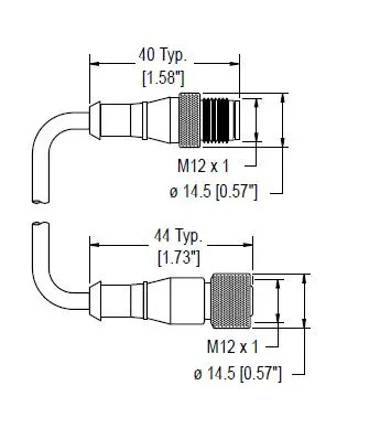
Connections
Integral 4-pin M12 male quick disconnect
Environmental Rating
Rated IEC IP50
Vibration and Mechanical Shock
- Vibration: 10 Hz to 55 Hz, 1.0 mm peak-to-peak amplitude per IEC 60068-2-6
- Shock: 15G 11 ms duration, half sine wave per IEC 60068-2-27
Operating Temperature
40 °C to +50 °C (–40 °F to +122 °F)
Storage Temperature:
40 °C to +70 °C (–40 °F to +158 °F)
Light Characteristics
RGBW LED PWM Frequency: 2kHz
|
Color | Dominant Wavelength (nm) or Color Temperature (CCT) |
CRI | Color Coordinates 1 | Lumens at Specified Length (Typical at 25 °C) 2 | ||||||
| X | Y | 145 mm | 285 mm | 430 mm | 570 mm | 850 mm | 1130 mm | |||
| Daylight White | 5000K | 82 | 0.345 | 0.352 | 160 | 320 | 480 | 640 | 960 | 1280 |
| Incandescent White | 2700K | 55 | 0.460 | 0.411 | 110 | 220 | 330 | 440 | 660 | 880 |
| Warm White | 3000K | 65 | 0.440 | 0.404 | 110 | 220 | 330 | 440 | 660 | 880 |
| Fluorescent White | 4100K | 90 | 0.376 | 0.374 | 145 | 290 | 435 | 580 | 870 | 1160 |
| Neutral White | 5700K | 82 | 0.328 | 0.337 | 160 | 320 | 480 | 640 | 960 | 1280 |
| Cool White | 6500K | 82 | 0.314 | 0.324 | 160 | 320 | 480 | 640 | 960 | 1280 |
| Green | 522 | – | 0.153 | 0.704 | 145 | 290 | 435 | 580 | 870 | 1160 |
| Red | 620 | – | 0.688 | 0.310 | 55 | 110 | 165 | 220 | 330 | 440 |
| Yellow | 574 | – | 0.447 | 0.488 | 95 | 190 | 285 | 380 | 570 | 760 |
| Blue | 467 | – | 0.140 | 0.061 | 40 | 80 | 120 | 160 | 240 | 320 |
| Magenta | – | – | 0.348 | 0.155 | 50 | 100 | 150 | 200 | 300 | 400 |
| Cyan | 490 | – | 0.146 | 0.308 | 110 | 220 | 330 | 440 | 660 | 880 |
| Amber | 589 | – | 0.542 | 0.417 | 80 | 160 | 240 | 320 | 480 | 640 |
| Rose | – | – | 0.486 | 0.217 | 50 | 100 | 150 | 200 | 300 | 400 |
| Lime Green | 562 | – | 0.376 | 0.538 | 110 | 220 | 330 | 440 | 660 | 880 |
| Orange | 599 | – | 0.605 | 0.371 | 70 | 140 | 210 | 280 | 420 | 560 |
| Sky Blue | 483 | – | 0.143 | 0.213 | 90 | 180 | 270 | 360 | 540 | 720 |
| Violet | – | – | 0.223 | 0.097 | 45 | 90 | 135 | 180 | 270 | 360 |
| Spring Green | 505 | – | 0.150 | 0.518 | 130 | 260 | 390 | 520 | 780 | 1040 |
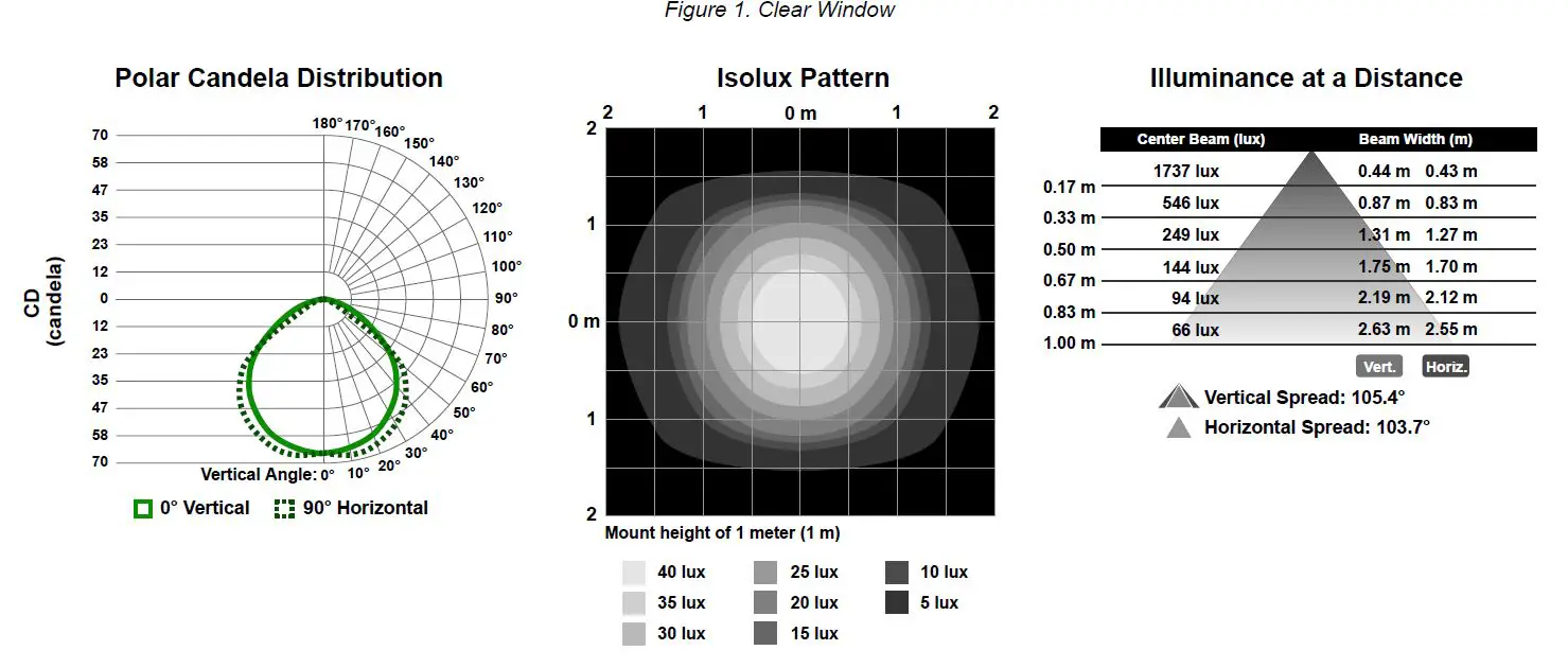
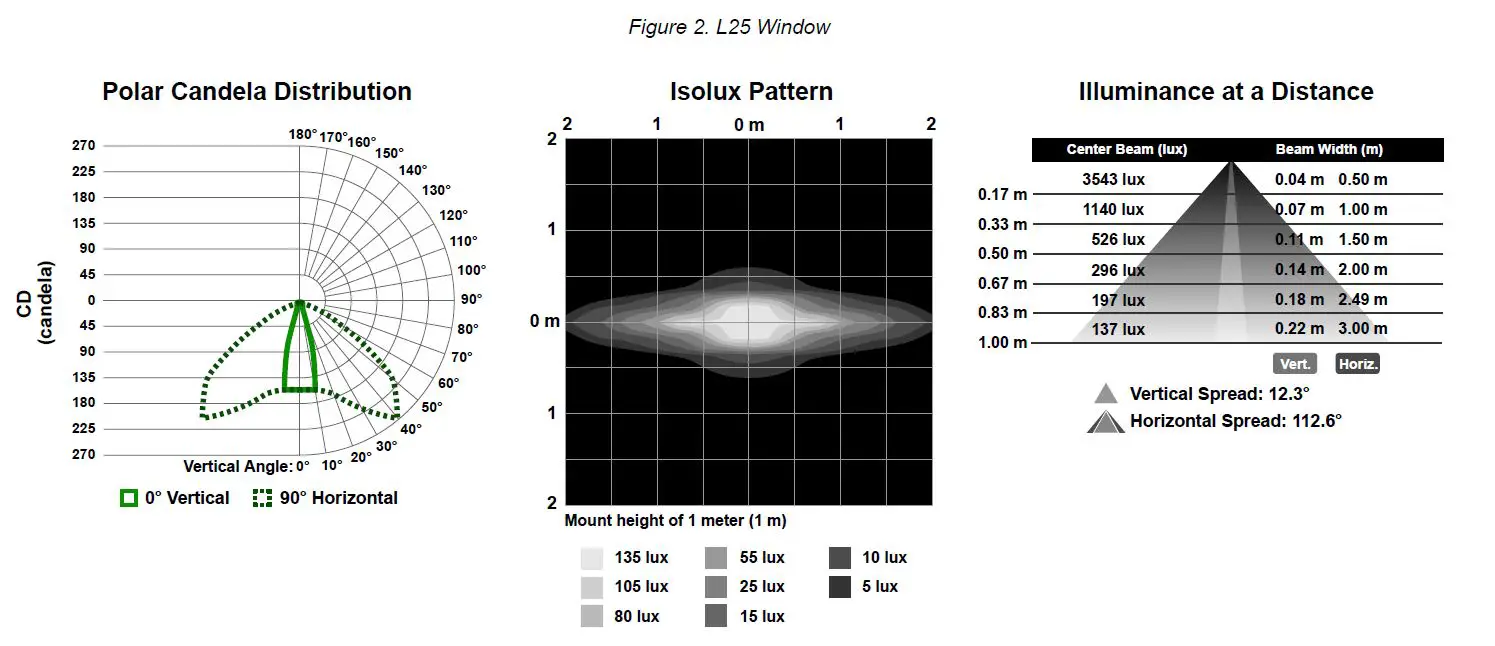
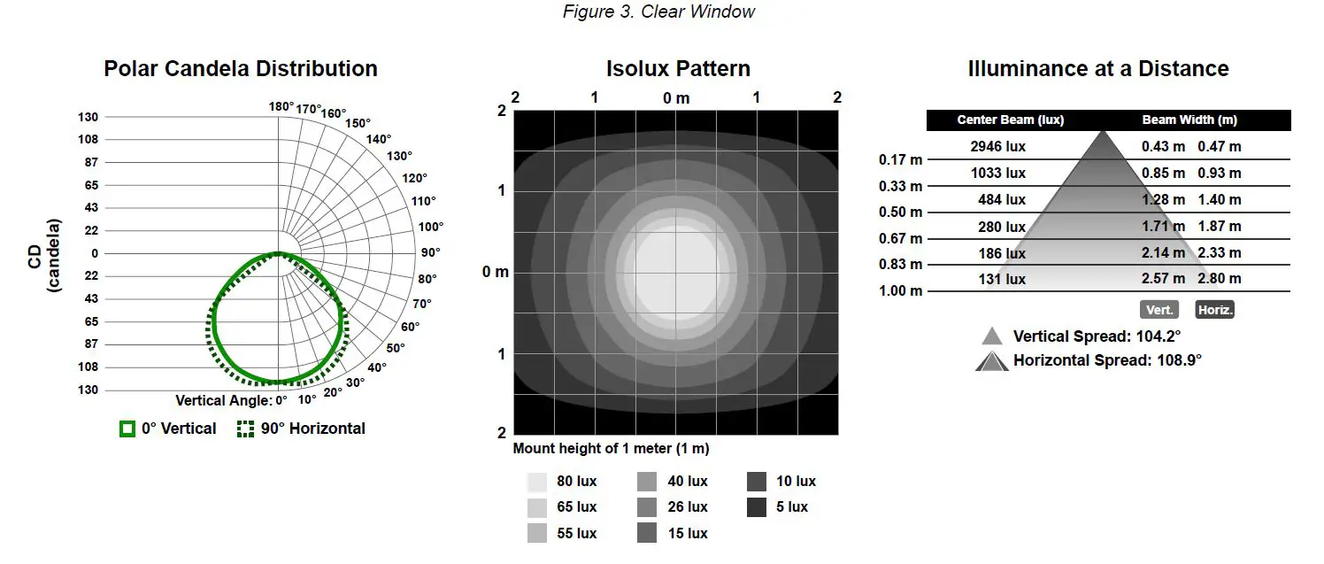
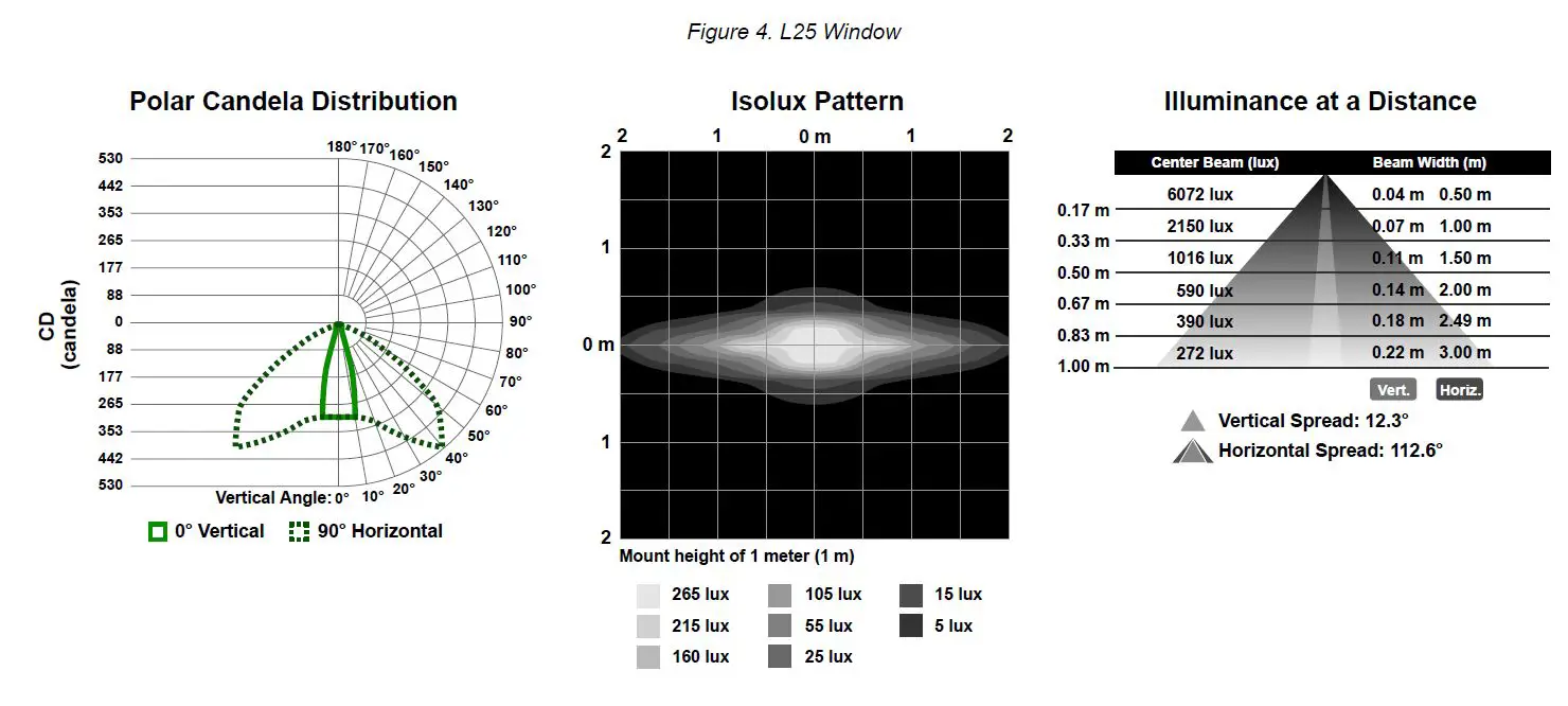
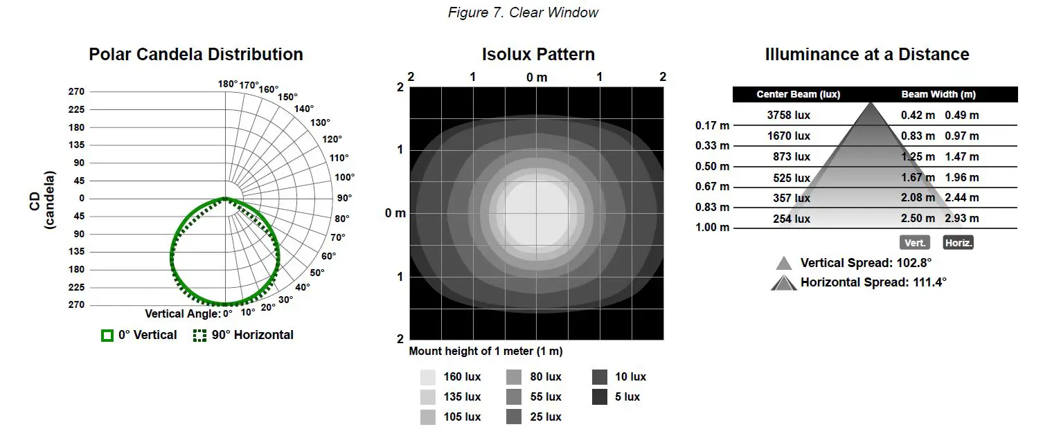
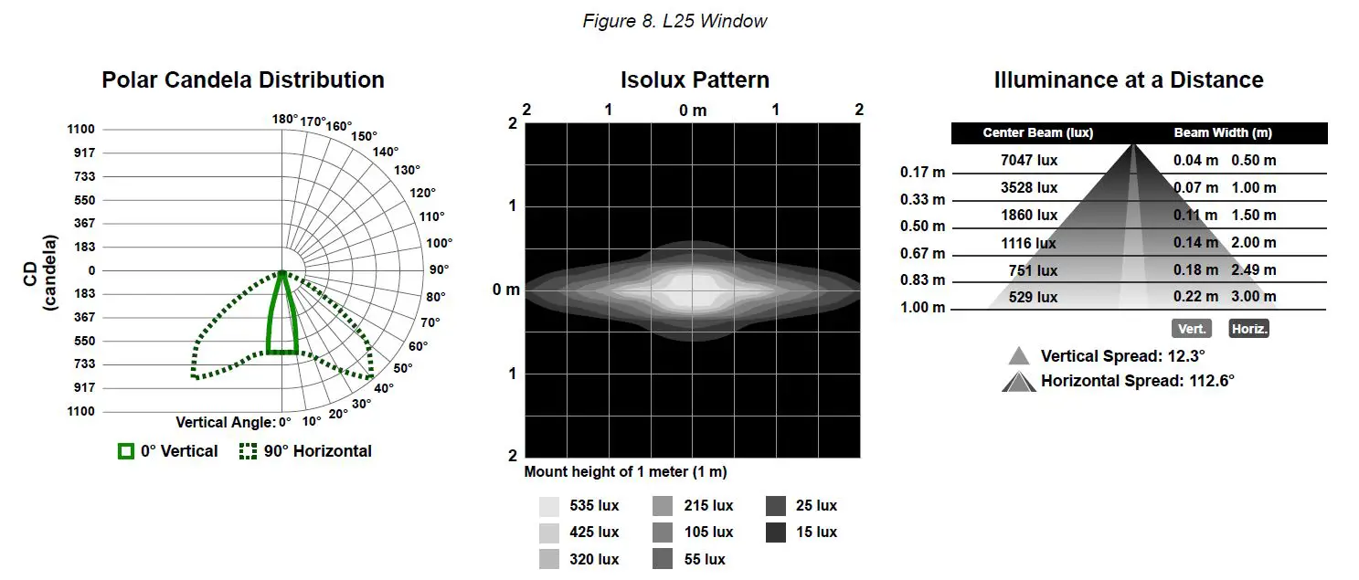
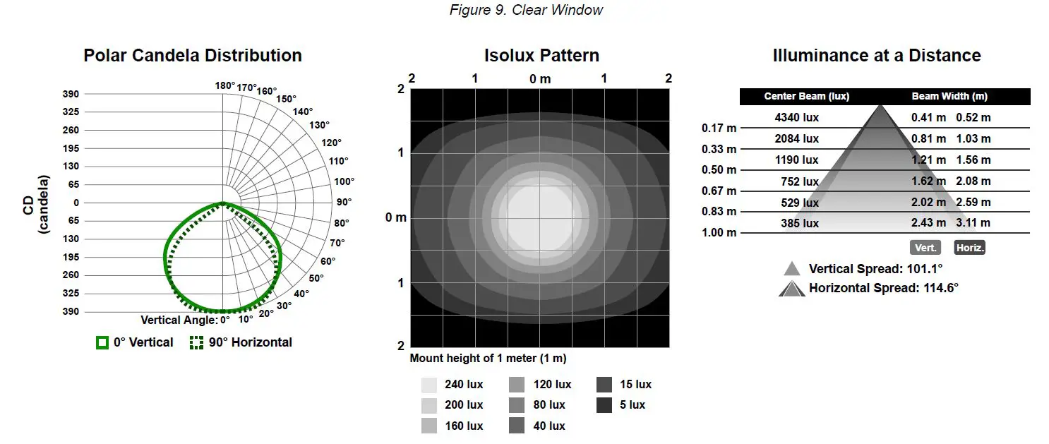
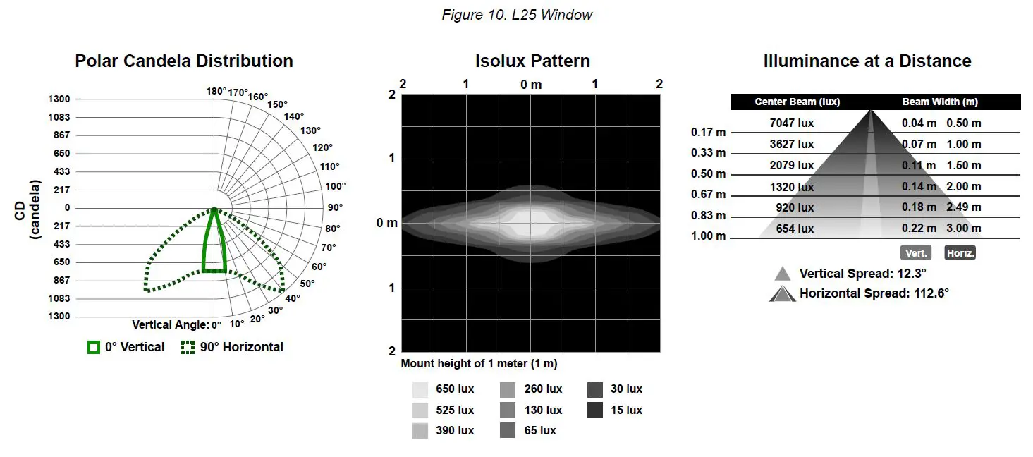
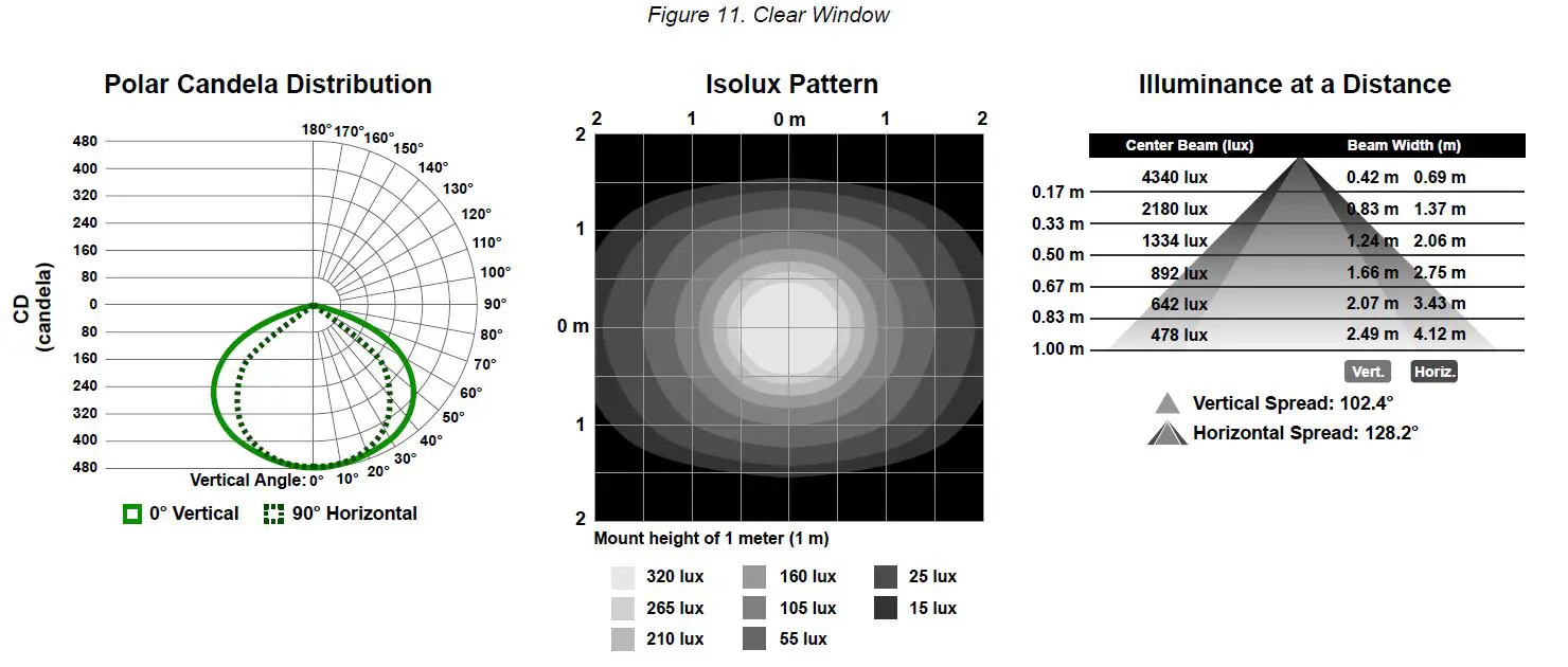
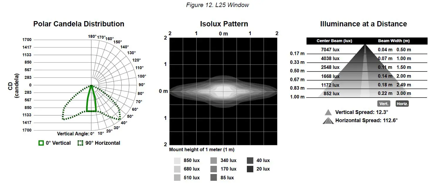
Photometric Data
Photometric data shown below is for standard clear, and 25° clear window daylight white models only. To get lux and candela values for other colors, multiply the values shown on the charts by the following factors:
- Incandescent White: 0.688
- Warm White: 0.688
- Fluorescent White: 0.906
- Neutral White: 1.000
- Cool White: 1.000
- Green: 0.906
- Red: 0.344
- Yellow: 0.594
- Blue: 0.250
- Magenta: 0.313
- Cyan: 0.688
- Amber: 0.500
- Rose: 0.313
- Lime Green: 0.688
- Orange: 0.438
- Sky Blue: 0.563
- Violet: 0.281
- Spring Green: 0.813
For models with a standard diffused window, multiply lux and candela values by an additional 0.750. Photometric data for 25°diffused lensed models is not shown.
145 mm Models
285 mm Models
430 mm Models


570 mm Models
850 mm Models
1130 mm Models
Dimensions
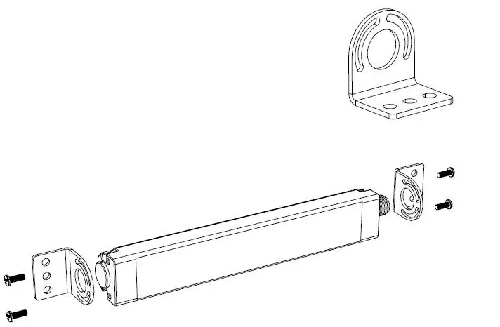
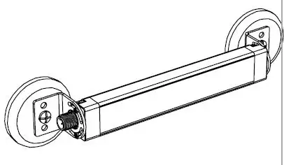
Dimensions are shown with the included SMBWLS28RA bracket.
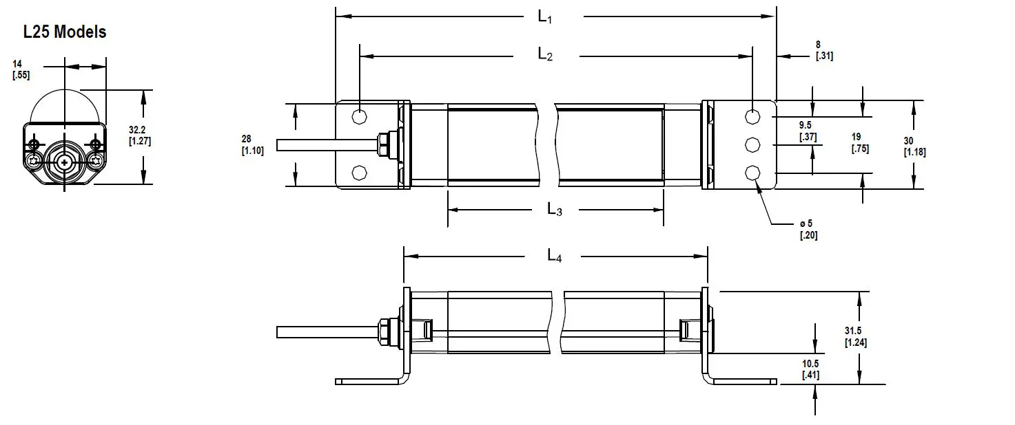
| Models | L1 | L2 | L3 | L4 |
| WLS28..145.. | 221 mm (8.7 in) | 205 mm (8.1 in) | 145 mm (5.71 in) | 175 mm (6.9 in) |
| WLS28..285.. | 362 mm (14.3 in) | 346 mm (13.6 in) | 286 mm (11.26 in) | 316 mm (12.4 in) |
| WLS28..430.. | 503 mm (19.8 in) | 487 mm (19.2 in) | 427 mm (16.81 in) | 457 mm (18.0 in) |
| WLS28..570.. | 644 mm (25.4 in) | 628 mm (24.7 in) | 568 mm (22.36 in) | 598 mm (23.5 in) |
| WLS28..850.. | 926 mm (36.5 in) | 910 mm (35.8 in) | 850 mm (33.46 in) | 880 mm (34.6 in) |
| WLS28..1130.. | 1208 mm (47.6 in) | 1192 mm (46.9 in) | 1132 mm (44.57 in) | 1162 mm (45.7 in) |
Accessories
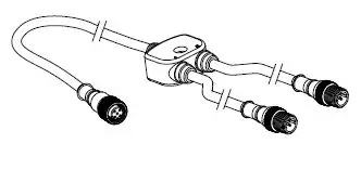
Cordsets
CSB-M1251FM1251M
- 5-pin parallel Y splitter (Male-Male-Female)
- For full Pro Editor preview capability
- Requires external power supply, sold separately
PSD-24-4
- 90 to 264 V AC 50/60 Hz input
- Includes a 1.8 m (6 ft) US style 5-15P input plug
- 24 V DC UL Listed Class 2 M12 connector output
- 4 A total current
WLS28 Pro LED Strip Light with IO-Link
| 4-Pin Threaded M12 Cordsets—Double Ended | |||||
| Model | Length | Style | Dimensions | Pinout | |
| MQDEC-401SS | 0.31 m (1 ft) |
|
1 4
2
3 | 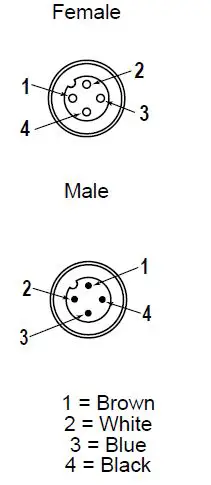 | |
| MQDEC-403SS | 0.91 m (2.99 ft) | ||||
| MQDEC-406SS | 1.83 m (6 ft) | ||||
| MQDEC-412SS | 3.66 m (12 ft) | ||||
| MQDEC-420SS | 6.10 m (20 ft) | ||||
| MQDEC-430SS | 9.14 m (30.2 ft) | Male Straight/ | |||
| Female Straight | |||||
| MQDEC-450SS | 15.2 m (49.9 ft) | ||||
Brackets
SMBWLS28RA
The bracket kit is available as a replacement for the one that comes with the light or switch. The kit contains two end brackets and four screws.
SMBWLS28SP
- Stainless steel snap bracket kit
- Includes two brackets

SMBWLSMAG
Magnetic mounting bracket for easy attachment to steel surfaces
SMBWLSMAGR
Protective cover also available to prevent scratches to painted surfaces
SMBWLS28SM
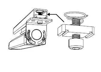
This kit allows the light or switch to be mounted at a right angle to the mounting surface. The kit contains two end brackets and four screws.
SMH1316
This kit allows the light or switch to be mounted to a 13/16-inch Unistrut channel. Light is shown. The kit includes:
- #10-32 spring nuts (qty 2)
- #10-32 socket head cap screws (qty 2)
- #10 lock washers (qty 2)
Banner Engineering Corp. warrants its products to be free from defects in material and workmanship for one year following the date of shipment. Banner Engineering Corp. will repair or replace, free of charge, any product of its manufacture which, at the time it is returned to the factory, is found to have been defective during the warranty period. This warranty does not cover damage or liability for misuse, abuse, or the improper application or installation of the Banner product.
THIS LIMITED WARRANTY IS EXCLUSIVE AND IN LIEU OF ALL OTHER WARRANTIES WHETHER EXPRESS OR IMPLIED (INCLUDING, WITHOUT LIMITATION, ANY WARRANTY OF MERCHANTABILITY OR FITNESS FOR A PARTICULAR PURPOSE), AND WHETHER ARISING UNDER COURSE OF PERFORMANCE, COURSE OF DEALING OR TRADE USAGE.
This Warranty is exclusive and limited to repair or, at the discretion of Banner Engineering Corp., replacement. IN NO EVENT SHALL BANNER ENGINEERING CORP. BE LIABLE TO BUYER OR ANY OTHER PERSON OR ENTITY FOR ANY EXTRA COSTS, EXPENSES, LOSSES, LOSS OF PROFITS, OR ANY INCIDENTAL, CONSEQUENTIAL OR SPECIAL DAMAGES RESULTING FROM ANY PRODUCT DEFECT OR FROM THE USE OR INABILITY TO USE THE PRODUCT, WHETHER ARISING IN CONTRACT OR WARRANTY, STATUTE, TORT, STRICT LIABILITY, NEGLIGENCE, OR OTHERWISE.
Banner Engineering Corp. reserves the right to change, modify or improve the design of the product without assuming any obligations or liabilities relating to any product previously manufactured by Banner Engineering Corp. Any misuse, abuse, or improper application or installation of this product or use of the product for personal protection applications when the product is identified as not intended for such purposes will void the product warranty. Any modifications to this product without prior express approval by Banner Engineering Corp will void the product warranties. All specifications published in this document are subject to change; Banner reserves the right to modify product specifications or update documentation at any time. Specifications and product information in English supersede that which is provided in any other language. For the most recent version of any documentation, refer to:
www.bannerengineering.com.
For patent information, see www.bannerengineering.com/patents.
FCC Statement
FCC Part 15 and CAN ICES-3 (B)/NMB-3(B)
This device complies with part 15 of the FCC Rules and CAN ICES-3 (B)/NMB-3(B). Operation is subject to the following two conditions:
- This device may not cause harmful interference, and
- This device must accept any interference received, including interference that may cause undesired operation.
This equipment has been tested and found to comply with the limits for a Class B digital device, pursuant to part 15 of the FCC Rules and CAN ICES-3 (B)/NMB-3(B). These limits are designed to provide reasonable protection against harmful interference in a residential installation. This equipment generates, uses and can radiate radio frequency energy and, if not installed and used in accordance with the instructions, may cause harmful interference to radio communications. However, there is no guarantee that interference will not occur in a particular installation. If this equipment does cause harmful interference to radio or television reception, which can be determined by turning the equipment off and on, the user is encouraged to try to correct the interference by one or more of the following measures:
- Reorient or relocate the receiving antenna.
- Increase the separation between the equipment and receiver.
- Connect the equipment into an outlet on a circuit different from that to which the receiver is connected.
- Consult the manufacturer.


