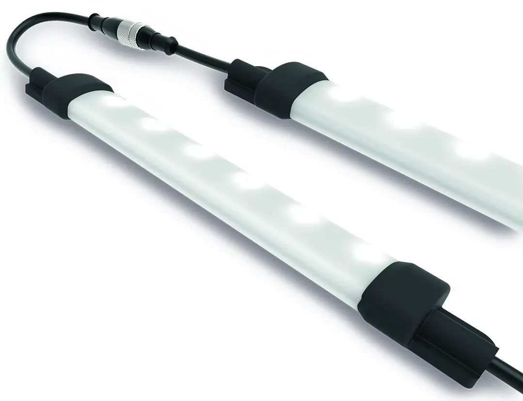

Banner’s WLS15 LED Strip Lights have sturdy aluminum inner frames, encased in shatter resistant, UV-stabilized, polycarbonate shells, making them ideal for indoor and outdoor applications.
- Bright, programmable strip light with RGB LEDs
- 19 color options for varied indication and inspection uses
- Programmable using Banner’s Pro Editor software and Pro Converter Cable
- Pro Editor software configuration and three discrete inputs gives access to color, flashing, intensity, and animation settings, as well as advanced operating modes for displaying distance, count, time and position
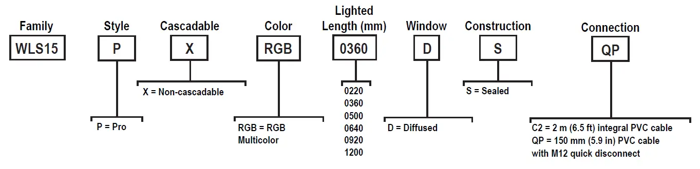
- Available in six lengths from 220 mm to 1200 mm
- Low-profile, space-saving design
- Rugged, water-resistant design
Important: Read the following instructions before operating the light. Please download the complete WLS15 Pro LED Strip Light technical documentation, available in multiple languages, from www.bannerengineering.com for details on the proper use, applications, Warnings, and installation instructions of this device.
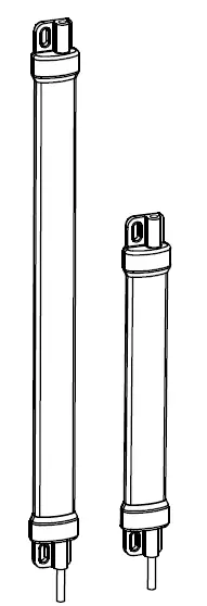
Models
Configuration Instructions
Pro Editor
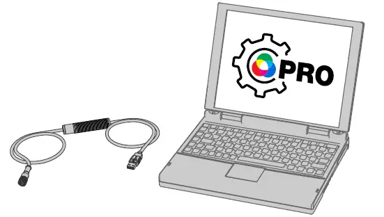
Use Banner’s Pro Editor software and Pro Converter Cable to create custom configurations by selecting different colors, flash patterns, and animations.
For more information visit www.bannerengineering.com/proeditor
Full Preview Connection (Required)
The full preview connection must be used for the TL50 Pro Tower Light, the K90 Pro Indicator, and for Pro-series Strip Lights, and is optional but recommended for other Pro-series enabled devices.
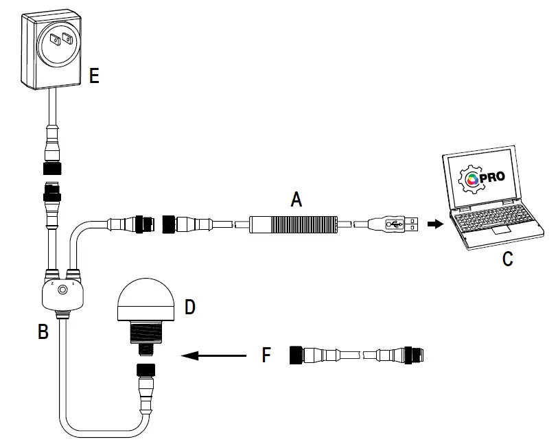
A = Pro Converter Cable (MQDC-506-USB)
B = Splitter (CSB-M1251FM1251M)
C = PC running Pro Editor software
D = Any Banner Pro Series-enabled device (K50 shown)
E = Power Supply (PSW-24-1 or PSD-24-4)
F = 8-Pin to 5-Pin Double-Ended Cordset (MQDC-801-5M-PRO), required for 8-Pin models
Wiring Diagrams
| Male | Pin | Wire Color | Description 1 |
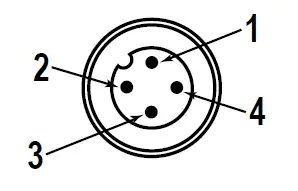 | 1 | Brown | Input 1 |
| 2 | White | Input 3 | |
| 3 | Blue | DC common | |
| 4 | Black | Input 2 |
| 7 Color Binary Control (Binary input state controls color, default configuration) | |||
| Input 1: Pin 1 Brown Wire | Input 2: Pin 4 Black Wire | Input 3: Pin 2 White Wire | LED Color |
| — | — | — | Light OFF |
| 12 V DC to 30 V DC | — | — | Red |
| — | 12 V DC to 30 V DC | — | Green |
| — | — | 12 V DC to 30 V DC | Yellow |
| 12 V DC to 30 V DC | 12 V DC to 30 V DC | — | Blue |
| 12 V DC to 30 V DC | — | 12 V DC to 30 V DC | Daylight White |
| — | 12 V DC to 30 V DC | 12 V DC to 30 V DC | Daylight White with Red Ends Flash |
| 12 V DC to 30 V DC | 12 V DC to 30 V DC | 12 V DC to 30 V DC | Blue Bounce with Daylight White Background |
Pro Editor Configuration for the WLS15 Pro
Banner’s Pro Editor software offers an easy way to configure Pro Series-enabled touch and indicator devices, allowing users full control of device states. The easy-to-use configuration software provides a variety of tools and capabilities to solve a wide range of applications. Configure any Pro Series-enabled device using the free Pro Editor software, available for download at www.bannerengineering.com/proeditor.
Machine and Work Cell—Choose colors and animations to create up to seven discretely controlled illumination and status states. Spans functionality from single segment to two-colored animations.
- Single Segment—The single segment option shows the WLS15 in one solid color. The input wires are used to change colors. Flashing and intensity options are available. Presets are available for common configurations, which can be adjusted as desired.
- End Status—The end status option shows the inside section of the WLS15 in one color and the ends of the light in another. The size of the two sections are customizable. The input wires are used to change color states. Flashing and intensity options are available.
- Process Visualization—The process visualization option enables a choice of colors, animations, speeds, and intensities to provide visual information that corresponds to equipment or process status. Single color illumination states are also available.
- Tower Light—Choose colors, intensities, and animations to create a discretely controlled two or three segment indicator. The segments are controlled independently with input wires.
- Mobile—Choose colors and animations to create states that can be used for advanced and intuitive indications on mobile equipment.
- Basic Warning—Choose colors, intensities, and animation to create a discretely controlled three segment indicator for communication of equipment status. The segments are controlled independently with input wires.
- Advanced Warning—Create up to seven discretely controlled status indicators, and use presets for Loading and Emergency Stop conditions. Colors, animations, speeds, and intensities provide equipment status.
- Timer—The timer option uses the WLS15 as a timer, counting up or counting down. Set the total time and choose up to four thresholds to change the visual appearance of the light as time advances. The timer starts when 12 V DC to 30 V DC is applied to the timer run input wire (pin 2 or white wire), and paused when left floating or tied to ground. The timer resets when 12 V DC to 30 V DC is applied to the reset wire (pin 4 or black wire). The timer automatically resets when it reaches the final count. A steady global background or threshold markers can be applied, from which color and intensity can be defined.
- Counter—The counter option counts up or down by converting input pulses into movement of LEDs along the length of the light based on up to four thresholds that define colors, intensity, and flashing. When the rising edge of an 12 V DC to 30 V DC pulse is applied to the counter input wire (pin 2 or white wire), the count increases by one. The user can choose whether the counter resets or the count decreases by one when 12 V DC to 30 V DC is applied to the control input wire (pin 4 or black wire). The counter automatically resets when it reaches the final count. A steady global background or threshold markers can be applied, from which color and intensity can also be defined.
- Pick Put Build—Choose colors and animations to create states that can be used to guide operators, signal material status, enable light-guided assembly, create pick-to-light operations, and enable kitting operations.
- Basic Segment—Choose colors, intensities, and animation to create a discretely controlled two or three segment indicator for communication of processes.
- Advanced Segment—Enable up to seven discretely controlled segments to be used as individual indications states. Only one segment can be enabled at once.
- Distance—The distance mode uses the light to display colored LEDs proportional to a PFM (pulse frequency modulation) or PWM (pulse width modulation) input and set range or with discretely controlled levels.
- Distance—The light adjusts position and color continuously based on the PFM or PWM input value (pin 2 or white wire) and defined color, flash, and intensity in up to four thresholds while maintaining an optional steady background for LEDs outside the active threshold range. Threshold markers can be applied, from which color and intensity can also be defined. The PFM signal frequency range can be from 100 to 10,000 Hz. The PWM duty cycle range can be from 0 to 100%.
- Coarse Distance—Choose colors, intensities, and flash patterns to create up to seven discretely controlled levels based upon input wiring logic states for simple distance and level indication.
- Gauge—The gauge option controls the color and position of a band of LEDs based on a defined PFM or PWM input value (pin 2 or white wire) and range. The width of the band is defined as a percentage of total lighted length. The light adjusts the position and color of the band and background continuously based on the input signal and defined color, flash, intensities, and animations in upper, lower, and center thresholds. Threshold markers can be applied, from which color and intensity can also be defined. The PFM signal frequency range can be from 100 to 10,000 Hz. The PWM duty cycle range can be from 0 to 100%.
Animation Settings
| Animation | Description |
| Off | Device OFF, no animation displays |
| Steady | Color 1 is solid ON at the defined intensity |
| Flash | Color 1 flashes at the defined speed, color intensity, and pattern (normal, strobe, three pulse, SOS, or random) |
| Two Color Flash | Color 1 and Color 2 flash alternately at the defined speed, color intensities, and pattern (normal, strobe, three pulse, SOS, or random) |
| Two Color Shift | Color 1 and Color 2 flash alternately on adjacent LEDs at defined speed and color intensities |
| Ends Steady | Color 1 defines the center 75% of the light. Color 2 defines the 12.5% of the light on each end. Center and ends are on steady. Center proportion can be defined in End Status mode |
| Ends Flash | Color 1 defines the center 75% of the light. Color 2 defines the 12.5% of the light on each end. The ends will flash at defined speed and pattern. Center proportion can be defined in End Status mode |
| Scroll | Color 1 defines a band 20% of the length of the light that moves in one direction up or down against the background of Color 2 at the defined speed and color intensities |
| Center Scroll | Color 1 defines a band 10% the length of the light that moves from the center of the light to the ends against the background of Color 2 at the defined speed and color intensity |
| Bounce | Color 1 defines a band 20% of the length of the light that moves up and down between the top and bottom of the light against the background of Color 2 at the defined speed and color intensities |
| Center Bounce | Color 1 defines a band 10% the length of the light that moves from the center of the light to the ends and back against the background of Color 2 at the defined speed and color intensity |
| Intensity Sweep | Color 1 continuously increases and decreases intensity between 0% to 100% at defined speed and color intensity |
| Two Color Sweep | Color 1 and Color 2 define the end values of a line across the color gamut. The light continuously displays a color by moving along the line at the defined speed and color intensity |
| Color Spectrum | The light scrolls through the 13 predefined colors with a different color on each LED at the defined speed, Color 1 intensity, and direction |
| Single End Steady | Color 1 is solid ON at the defined intensity on one end of the device |
| Single End Flash | Color 1 flashes at the defined speed, color intensity, and pattern (normal, strobe, three pulse, SOS, or random) on one end of the device |
By default, when the sub-applications for Machine and Work Cell are selected, Pro Editor opens I/O State configuration in Advanced. Three I/O states are available:
| I/O State Configuration Settings | Description |
| Basic | Configurations made in this state assign one wire to one state, with the following override control: • Pin 4 (Black) overrides Pin 1 (Brown) • Pin 2 (White) overrides Pins 1 and 4 (Brown and Black) |
| Advanced | I/O state with full seven state options for maximum configuration. Configurations made in Advanced assign binary wiring combinations of all valid inputs to each state. |
| I/O Block | Three state control for use with I/O block. Configurations made in I/O Block assign states to the black, white, and combination of black and white wires for use with I/O blocks for which power (brown) and common (blue) are always on for five pin connections. |
Specifications
Supply Voltage
12 V DC to 30 V DC
Use only with suitable Class 2 power supply (UL) or a SELV power supply (CE) See electrical characteristics on product label
| Light Length | Typical Current | Maximum Current | ||
| 12 V DC | 24 V DC | 30 V DC | A | |
| 0220 mm | 0.120 | 0.060 | 0.050 | 0.125 |
| 0360 mm | 0.240 | 0.120 | 0.100 | 0.250 |
| 0500 mm | 0.360 | 0.180 | 0.150 | 0.375 |
| 0640 mm | 0.480 | 0.240 | 0.200 | 0.500 |
| 0920 mm | 0.720 | 0.360 | 0.300 | 0.750 |
| 1200 mm | 0.960 | 0.480 | 0.400 | 1.000 |
Supply Protection Circuitry
Protected against reverse polarity and transient voltages
Note: Do not spray cable with high-pressure sprayer, or cable damage will result.
Input Rating
Leakage Current Immunity: 400 µA
Indicator On/Off Response Time: 300 ms (maximum)
- PWM Input Characteristics
Duty Cycle Range: 0 to 100%
Constant Frequency Range: 100 to 10000 Hz - PFM Input Characteristics
Frequency Range: 100 to 10000 Hz
Constant Duty Cycle Range: 10 to 90%
Construction
Clear anodized aluminum housing
Polycarbonate outer housing
Polyamide end caps
Connections
2 m (6.5 ft) integral PVC cable
150 mm (6 in) PVC cable with a 4-pin M12 male quick disconnect
Models with a quick disconnect require a mating cordset
Mounting
Integral mounting slots for M4 (#8) screws, tighten to 5 in·lbf max torque
Multiple bracket options available
Secure cables within 150 mm (5.9 in) of the light
Note: It is recommended to use the provided mounting bushings when mounting using the endcaps. Center the mounting bushings in each slot to allow for expansion and contraction. Install using a M4 (#8) screw in each bushing torqued to a maximum of 0.45 N-m (4 in-lbf). For 920 mm and 1200 mm models in environments that vary more than 10 °C (18 °F), it is recommended to use one of the mounting bracket options instead of the end cap slots. If using the LMBWLS15 clip bracket and additional attachment is desired, only one end may be fastened using one of the spacers provided in the LMBWLS15 hardware packet to allow the opposite end to expand and contract. See mounting options in the instruction manual for bracket and tape options that allow expansion and contraction over temperature variations.
Light Characteristics
RGB LED PWM Frequency: 1kHz
|
Color | Dominant Wavelength (nm) or Color Temperature (CCT) | Color Coordinates 2 | Lumens at Specified Length (Typical at 25 °C) | ||||||
| X | Y | 220 mm | 360 mm | 500 mm | 640 mm | 920 mm | 1200 mm | ||
| Daylight White | 5000K | 0.345 | 0.352 | 30 | 60 | 90 | 120 | 180 | 240 |
| Incandescent White | 2700K | 0.460 | 0.411 | 30 | 60 | 90 | 120 | 180 | 240 |
| Warm White | 3000K | 0.440 | 0.404 | 30 | 60 | 90 | 120 | 180 | 240 |
| Fluorescent White | 4100K | 0.376 | 0.374 | 30 | 60 | 90 | 120 | 180 | 240 |
| Neutral White | 5700K | 0.328 | 0.337 | 30 | 60 | 90 | 120 | 180 | 240 |
| Cool White | 6500K | 0.314 | 0.324 | 30 | 60 | 90 | 120 | 180 | 240 |
| Green | 532 | 0.181 | 0.735 | 45 | 90 | 135 | 180 | 270 | 360 |
| Red | 621 | 0.691 | 0.308 | 25 | 50 | 75 | 100 | 150 | 200 |
| Yellow | 578 | 0.473 | 0.474 | 35 | 70 | 105 | 140 | 210 | 280 |
| Blue | 467 | 0.137 | 0.056 | 10 | 20 | 30 | 40 | 60 | 80 |
| Magenta | – | 0.379 | 0.177 | 20 | 40 | 60 | 80 | 120 | 160 |
| Cyan | 492 | 0.150 | 0.334 | 30 | 60 | 90 | 120 | 180 | 240 |
| Amber | 590 | 0.552 | 0.414 | 30 | 60 | 90 | 120 | 180 | 240 |
| Rose | – | 0.508 | 0.230 | 25 | 50 | 75 | 100 | 150 | 200 |
| Lime Green | 565 | 0.393 | 0.535 | 40 | 80 | 120 | 160 | 240 | 320 |
| Orange | 600 | 0.611 | 0.370 | 30 | 60 | 90 | 120 | 180 | 240 |
| Sky Blue | 485 | 0.146 | 0.241 | 25 | 50 | 75 | 100 | 150 | 200 |
| Violet | – | 0.212 | 0.091 | 15 | 30 | 45 | 60 | 90 | 120 |
| Spring Green | 509 | 0.157 | 0.553 | 40 | 80 | 120 | 160 | 240 | 320 |
Dimensions
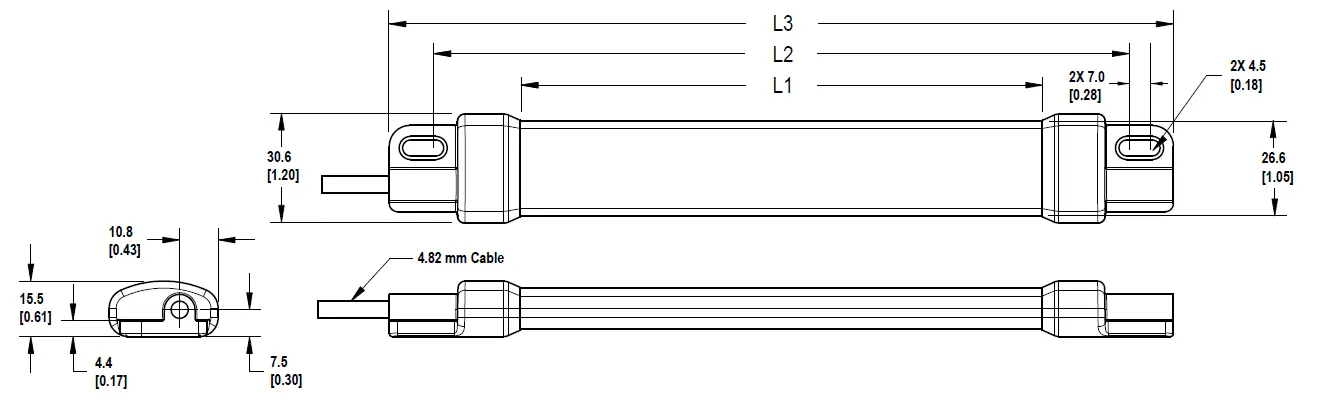
| Models | L1 | L2 | L3 |
| WLS15..0220.. | 146.4 mm (5.76 inches) | 194 mm (7.64 inches) | 220 mm (8.66 inches) |
| WLS15..0360.. | 286.4 mm (11.28 inches) | 334 mm (13.15 inches) | 360 mm (14.17 inches) |
| WLS15..0500.. | 426.4 mm (16.79 inches) | 474 mm (18.66 inches) | 500 mm (19.69 inches) |
| WLS15..0640.. | 566.4 mm (22.3 inches) | 614 mm (24.17 inches) | 640 mm (25.2 inches) |
| WLS15..0920.. | 846.4 mm (33.32 inches) | 894 mm (35.2 inches) | 920 mm (36.22 inches) |
| WLS15..1200.. | 1126.4 mm (44.35 inches) | 1174 mm (46.22 inches) | 1200 mm (47.24 inches) |
Accessories
Cordsets
PRO-KIT
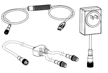
- Pro Converter Cable (MQDC-506-USB)
- Splitter (CSB-M1251FM1251M)
- Power Supply (PSW-24-1)
MQDC-506-USB
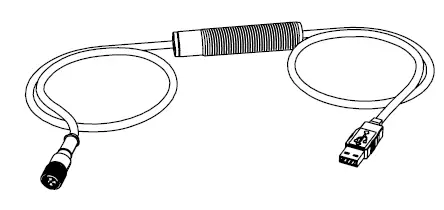
- Pro Converter Cable
- 1.83 m (6 ft) length 5-pin M12 quick disconnect to Device and USB to PC
- Required for connection to Pro Editor
CSB-M1251FM1251M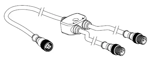
- 5-pin parallel Y splitter (Male-Male-Female)
- For full Pro Editor preview capability
- Requires external power supply, sold separately
PSW-24-1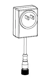
- 24 V DC, 1 A power supply
- 2 m (6.5 ft) PVC cable with M12 quick disconnect
- Provides external power with splitter cable, sold separately
PSD-24-4
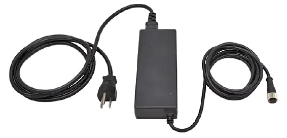
- 90 to 264 V AC 50/60 Hz input
- Includes a 1.8 m (6 ft) US style 5- 15P input plug
- 24 V DC UL Listed Class 2 M12 connector output
- 4 A total current
LC28PB2-3Q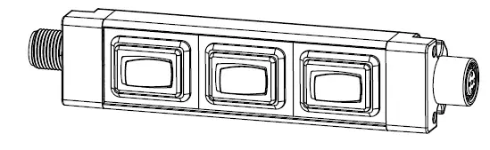
- In-line switch with M12 connectors
- Rugged metal housing
- Perfect for dc-powered task lights, indicators, and tower lights
- Rated for up to 30 V dc
| 4-Pin Threaded M12 Cordsets—Single Ended | |||||
| Model | Length | Style | Dimensions | Pinout (Female) | |
| MQDC-406 | 2 m (6.56 ft) |
Straight | 44 Typ.
M12 x 1 ø 14.5 |
2 1 3 4 |
1 = Brown 2 = White 3 = Blue 4 = Black |
| MQDC-415 | 5 m (16.4 ft) | ||||
| MQDC-430 | 9 m (29.5 ft) | ||||
| MQDC-450 | 15 m (49.2 ft) | ||||
| 4-Pin Threaded M12 Cordsets—Single Ended | ||||||||
| Model | Length | Style | Dimension | s | Pinout (Female) | |||
| MQDC-406RA | 2 m (6.56 ft) |
Right-Angle | 32 Typ. |
2
1 |
3
4 | |||
| MQDC-415RA | 5 m (16.4 ft) | |||||||
| [1.26″] | ||||||||
| MQDC-430RA | 9 m (29.5 ft) | |||||||
|
MQDC-450RA |
15 m (49.2 ft) | 30 Typ. | ||||||
| [1.18″] | ||||||||
| M12 x 1 | ||||||||
| ø 14.5 [0.57″] | ||||||||
Mounting Accessories
LMBWLS15
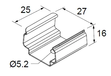
- Stainless steel clip bracket
- Includes 3 clip brackets and 2 plastic spacers
- Clearance hole for M5 hardware
LMBWLS15-150S
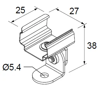
- Set of 2 stainless steel swivel bracket, allows for 150° of movement
- Clearance hole for M5 button head screw
LMBWLS15MAG
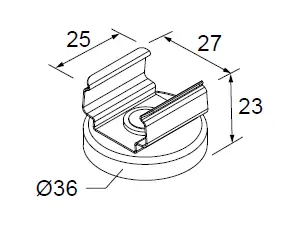
- Set of 2 brackets
- Magnetic mounting bracket for attachment to steel and iron surfaces
LMBWLS15TD
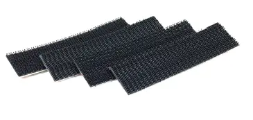
- Includes 4 100 mm (4 in) strips of 3M™ Dual Lock™ reclosable fasteners
- Recommended for mounting to metal and plastic surfaces
- Strong, pressure-sensitive adhesive bonds on contact
LMBWLS15TF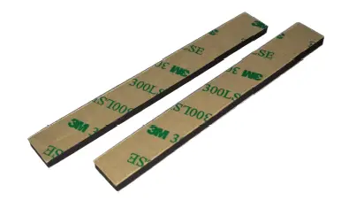
- Includes 2 100 mm (4 in) strips of double-sided foam urethane strips
- Acrylic adhesive provides high bond strength to most surfaces
- Bonds to low surface energy plastics such as polypropylene and powder coated paints
Banner Engineering Corp. warrants its products to be free from defects in material and workmanship for one year following the date of shipment. Banner Engineering Corp. will repair or replace, free of charge, any product of its manufacture which, at the time it is returned to the factory, is found to have been defective during the warranty period. This warranty does not cover damage or liability for misuse, abuse, or the improper application or installation of the Banner product.
THIS LIMITED WARRANTY IS EXCLUSIVE AND IN LIEU OF ALL OTHER WARRANTIES WHETHER EXPRESS OR IMPLIED (INCLUDING, WITHOUT LIMITATION, ANY WARRANTY OF MERCHANTABILITY OR FITNESS FOR A PARTICULAR PURPOSE), AND WHETHER ARISING UNDER COURSE OF PERFORMANCE, COURSE OF DEALING OR TRADE USAGE.
This Warranty is exclusive and limited to repair or, at the discretion of Banner Engineering Corp., replacement. IN NO EVENT SHALL BANNER ENGINEERING CORP. BE LIABLE TO BUYER OR ANY OTHER PERSON OR ENTITY FOR ANY EXTRA COSTS, EXPENSES, LOSSES, LOSS OF PROFITS, OR ANY INCIDENTAL, CONSEQUENTIAL OR SPECIAL DAMAGES RESULTING FROM ANY PRODUCT DEFECT OR FROM THE USE OR INABILITY TO USE THE PRODUCT, WHETHER ARISING IN CONTRACT OR WARRANTY, STATUTE, TORT, STRICT LIABILITY, NEGLIGENCE, OR OTHERWISE.
Banner Engineering Corp. reserves the right to change, modify or improve the design of the product without assuming any obligations or liabilities relating to any product previously manufactured by Banner Engineering Corp. Any misuse, abuse, or improper application or installation of this product or use of the product for personal protection applications when the product is identified as not intended for such purposes will void the product warranty. Any modifications to this product without prior express approval by Banner Engineering Corp will void the product warranties. All specifications published in this document are subject to change; Banner reserves the right to modify product specifications or update documentation at any time. Specifications and product information in English supersede that which is provided in any other language. For the most recent version of any documentation, refer to: www.bannerengineering.com
For patent information, see www.bannerengineering.com/patents.
FCC Part 15 and CAN ICES-3 (B)/NMB-3(B)
This device complies with part 15 of the FCC Rules and CAN ICES-3 (B)/NMB-3(B). Operation is subject to the following two conditions:
- This device may not cause harmful interference, and
- This device must accept any interference received, including interference that may cause undesired operation.
This equipment has been tested and found to comply with the limits for a Class B digital device, pursuant to part 15 of the FCC Rules and CAN ICES-3 (B)/NMB-3(B). These limits are designed to provide reasonable protection against harmful interference in a residential installation. This equipment generates, uses and can radiate radio frequency energy and, if not installed and used in accordance with the instructions, may cause harmful interference to radio communications. However, there is no guarantee that interference will not occur in a particular installation. If this equipment does cause harmful interference to radio or television reception, which can be determined by turning the equipment off and on, the user is encouraged to try to correct the interference by one or more of the following measures:
- Reorient or relocate the receiving antenna.
- Increase the separation between the equipment and receiver.
- Connect the equipment into an outlet on a circuit different from that to which the receiver is connected.
- Consult the manufacturer.
Mexican Importer
Banner Engineering de Mèxico, S. de R.L. de C.V. David Alfaro Siqueiros 103 Piso 2 Valle oriente San Pedro Garza Garcia Nuevo Leòn, C. P. 66269
81 8363.2714


