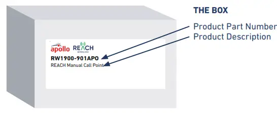
![]() RW1900-901APO Reach Manual Call Point
RW1900-901APO Reach Manual Call Point
User Manual
MOUNTING STEPS
Proceed as follows to complete the device installation:
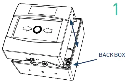
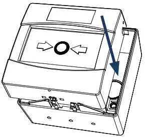
Remove the MCP front from the backbox using key provided.
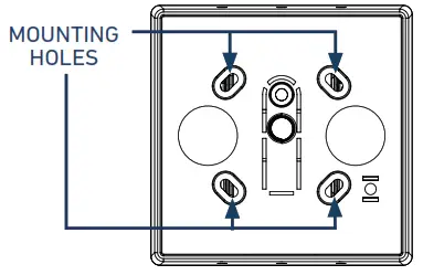
- Locate the mounting holes on the backbox and mark them using a pencil on the desired surface you are drilling.
- Using a suitable-sized drill bit (5.5mm) drill the marked screw points on your chosen surface.
- Ensure you use the correct fixings for the type of surface you are mounting to.
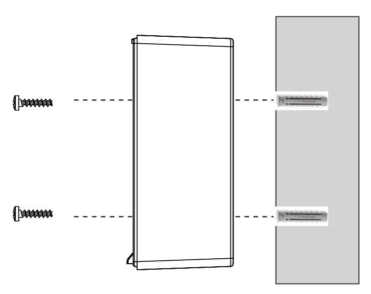
Screw the back box to the wall using all fixing holes and the supplied screws.
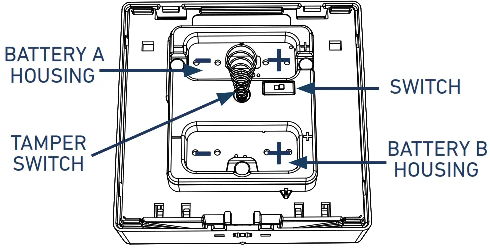
- Ensure the programming switch on the MCP is in position ON.
- Fit the 2x CR123A batteries ensuring you have checked they are the correct way round observing the polarity indications.
Screw the back box to the wall using all fixing holes and the supplied screws.
- Ensure the programming switch on the MCP is in position ON.
- Fit the 2x CR123A batteries ensuring you have checked they are the correct way round observing the polarity indications.
INSIDE THE BOX
- 1 x Manual Call Poin
- 2 x CR123A batteries
- 1 x Reset Key
- 2 x Screws
- 1 x Quick start guide
IMPORTANT TO CONSIDER
 When mounting a wireless device, a comprehensive radio survey should have been carried out to establish the location that provides the best coverage and optimum reach. Taking into consideration the building structure and materials, the survey identifies the wireless infrastructure required and product locations for optimum performance, identifying any factor that could prevent radio integrity.
Avoid fixing or mounting the unit close to the following:
- Equipment that utilises large electrical currents
- Large metal objects or structures
- Fluorescent lighting fittings
- Metal ceiling structures
- IT cabling.
Keep 2 meters minimum spacing between other wireless equipment in the area to avoid signal interference.![]() EN54 approved environmental temperature range is -10°C to +55°C
EN54 approved environmental temperature range is -10°C to +55°C
 https://www.apollo-fire.co.uk/products/
For more information, please refer to the user manual. Available on apollo-fire.co.uk
![]() Apollo Fire Detectors Ltd. 36 Brookside Road
Apollo Fire Detectors Ltd. 36 Brookside Road
Havant, Hampshire
United Kingdom, PO9 1JR
T: +44 (0)23 9244 2706
E: techsales@apollofire.com
W: www.apollo-fire.co.uk


