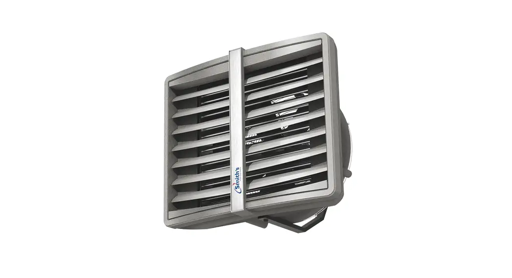
![]() Solano ® Eco
Solano ® Eco
Installation, commissioning and user manual Unit heater
Issue 002 | November 2022
| UK | IRL | SmithsEP.co.uk
Issue 002 – November 2022 | SmithsEP.co.uk | 1
Overall information
Solano heating and ventilation devices are designed to be applied in the buildings of small and medium capacity, such as: production and warehouse halls, car showrooms and service stations, sports halls and stadiums, sacral buildings and churches, retail stores and wholesales outlets, agricultural facilities and exhibition halls. Solano provides a dedicated solution for connection to low water temperature sources (for example condensing boilers and industrial heat pumps). Main advantages of Solano are: high temperature of outlet air is generated by low temperature of water supplied to a unit, maximum use of the heating coil surface – new geometry of coil construction (enhanced fins size, lower space between fins), optimised flow rate of heated outlet air – in effect high air exhaust temperature generated on each speed of fan.
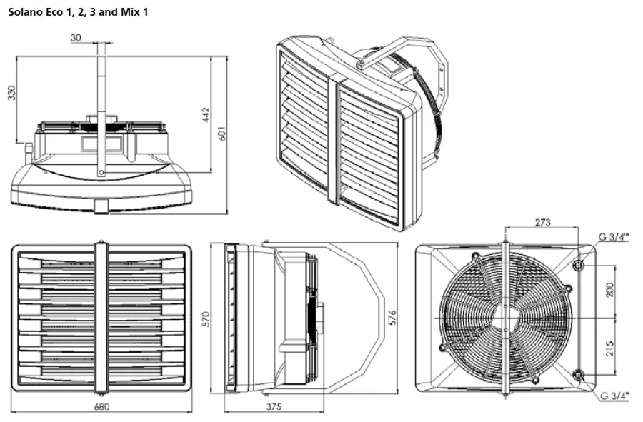
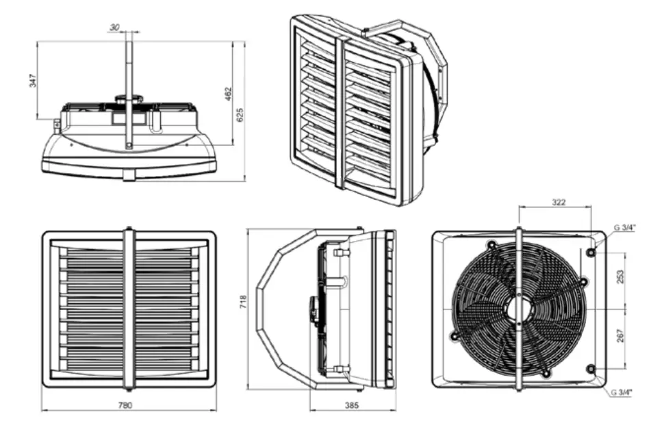
Dimensions
 Elements of the Solano devices
- Casing made of highly resistant EPP (expended polypropylene) material
- Regulated louvres
- 3 step axial fan 350 mm, 450 mm or 550mm dimension; protected from direct access to revolving elements with safety netting
- Heat exchanger – (Cu/AL) made of copper tubes placed in an aluminium lamellar exchanger/block with stub connection ½”, ¾”.
Stub connections are equipped with air-release valves and water agent release tion ½”, ¾”.Stub connections are equipped with air-release valves and water agent release
| Heater Eco 1 | Heater Eco 2 | Heater Eco 3 | Heater Eco MAX 1 | Heater Eco MAX 2 | Heater Eco MAX 3 | Heater Eco MIX 1 | Heater Eco MIX 2 | ||
| Heat output range* | kW | 10-35 | 15-50 | 20-70 | 25-70 | 35-95 | 40-120 | – | – |
| Heat output (90/70°C) / ΔT air temperature increase** | kW/°C | 23kW/18°C | 39kW/33°C | 50kW/48°C | 55kW/30°C | 74kW/49°C | 94kW/60°C | – | – |
| Heat output (70/50°C) / ΔT air temperature increase** | kW/°C | 16kW/13°C | 26kW/22°C | 35kW/34°C | 40kW/22°C | 53kW/35°C | 68kW/44°C | – | – |
| Heat output (50/30°C) / ΔT air temperature increase** | kW/°C | 9kW/8°C | 13kW/11°C | 20kW/20°C | 25kW/14°C | 32kW/21°C | 42kW/27°C | – | – |
| Max air output – III speed | m3/h | 3900 | 3350 | 2950 | 5700 | 5600 | 5100 | 4800 | 7200 |
| Sound level I/II/III speed**** | dB (A) | 44/52/62 | 41/50/60 | 39/48/60 | 41/50/59 | 40/48/58 | 40/48/58 | 36/44/54 | 31/42/49 |
| Number of coil rows | – | 1 | 2 | 3 | 2 | 3 | 3 | – | – |
| Max working pressure | Mpa | 1.6 | 1.6 | – | – | ||||
| Max airflow range***** | m | 24 | 21 | 19 | 26 | 25 | 23 | 13*** | 16*** |
| Diameter of connection nozzles | inches | 3/4” | 3/4” | – | – | ||||
| Power supply | V/Hz A | 230/50 1.08A | 230/50 2.2A | 230/50 1.08A | 230/50 2.2A | ||||
| Motor power | W | 250 | 520 | 250 | 520 | ||||
| Motor speed | rpm | 1350 | 1380 | 1350 | 1380 | ||||
| Protection class IP | – | IP54 | IP54 | IP54 | |||||
| Weight without water/with water | kg | 10.8/11.9 | 12.7/14.8 | 14.5/16.9 | 23.6/25.2 | 25.2/27.4 | 25.5/28 | 9.2 | 15.8 |
* presented heat output for water agent temperature range 50/30°C – 120-90°C, air inlet temperature 0°C, III speed.
** for air inlet temperature 0°C
*** max height of installation for vertical airflow, max working area 380 m² for HEATER MIX 1 and 450 m² for HEATER MIX 2 **** measured in distance of 5m
***** Horizontal range of isothermal steam at velocity of 0,5m/s
General information
Solano heating and ventilation devices are manufactured in compliance with standards concerning quality, ecology, utility and work comfort. Solano devices are delivered ready-to-use in a cardboard package that is to protect from mechanical damages damage during transit. The package consists of: the device, wall mounting bracket, the Manual (Operation and Maintenance Documentation) and Guarantee. If the optional automatic control ordered, it shall be delivered in a separate package. Make sure all the aforementioned elements are in the package immediately after the delivery. In the absence of any element, please advise Smith’s immediately.
ATTENTION!
- Before mounting read the manual carefully and adhere to the rules concerning the mounting procedures. Failure to do so, may result in inappropriate functioning of the device and the loss of the guarantee rights.
- Pay special attention when working with electrical elements of the device.
- Any installation operations must be carried out by qualified persons with appropriate authorisations
Assembly
Prior to any installation procedures, take the following aspects into consideration: easy access for maintenance works, access to water and electrical installation, appropriate air distribution in a room.
Each Solano unit is equipped with a set of 2 interchangeable colour inserts; in order to change the colour, remove the insert from the front panel and place the desired one back in place. It is advisable to mount the device to the wall or the ceiling on original mounting brackets, supporting mount pins (not delivered with the device) or supporting constructions (shapes and dimensions of the supporting construction may be individually designed in compliance with durability and strength requirements).
In case of mounting to the ceiling, pay attention to the fact that air-release/venting of the device may be difficult so it is advisable to place vent at the highest point of the pipework. The device may be mounted to the wall with the use of a mounting bracket at the angle of 0°, 30° or 60 °. A mounting bracket holder is made of curved profile. It has two holes for vertical assembly. Assembly to the wall and/or to the ceiling is possible at different angles but it requires making necessary holes in the holder.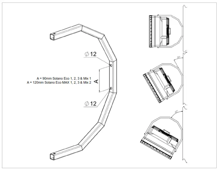
 Mounting bracket to the Solano
The bracket set consist of: a holder, two sleeves, two M8 screws and washers.
In order to mount the bracket, drill two @12-13mm holes in places visibly marked on the casing.
Insert sleeves into drilled holes and place the bracket in. The included holder must be screwed with MB screws with washers.
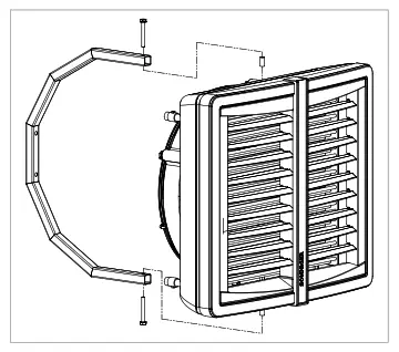
 Installation of mounting pins
‘To mount the heater to the ceiling, use M3 mounting pins.
Drill two @8-9mm holes in places visibly marked on the casing.
Mounting pins may be screwed into the frame not deeper than 20mm.
ATTENTION!
* While drilling the holes in marked places be careful not to damage the coil by going deeper than 20mm!
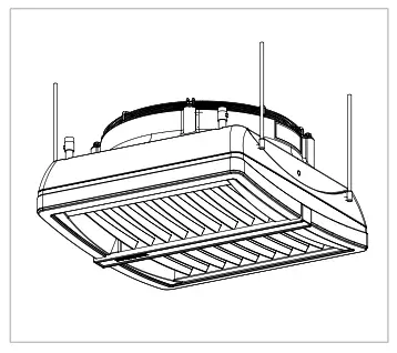 Assembly cf Solane MIX air mixer
To mount Solano MIX aar maxer to the ceding, use MB mounting pans. Oril two @8-9men holes in places vsibly marked on the casing.
Mounting pins may be screwed into the frame of a heat exchanger to the maximum depth of 20mm. Mounting pans and connecting elements are not included with the unit.
NOTICE!
- To sustain proper functioning of the device keep a safe distance – 200 mm from its sides and 300 mm from its backside to the fan
Electrical installation
The electrical installation and connection to power supply must be done in compliance with the existing regulations and standards for building industry.
The fan’s engine is equipped with the internal temperature limit fuse protecting the engine from its overheating.
The unit set does not consist of: a feeding cable, a master switch (see diagram)
The electrical installation must be done by an authorised person, acquainted with the Manual. The connection of the feeding cable and master switch must be done in compliance with electnical diagram (with or without the automatic control, depending on the option chosen). Any and all damages incurred as a result of the aforementioned causes are not provided with the Guarantee and the user will be charged with any costs of the device exchange. The connection of the automatic control should be carried out in accordance with the electrical diagram.
In case of any doubts or problems, unplug the device and contact the device’s installer or Smith’s Authorised Service.
Water installation
The installation of the unit should be done in a way enabling maintenance service; on both stub pipes manual closing valves should be installed in order to cut off the device. Feeding cables of the heater shall be connected in accordance with the symbols/marking on the casing (inlet/outlet). In case of electromagnetic valve (with the option of the automatic control) it should be installed on the outlet as it may be damaged otherwise. When the pipework is being connected to the exchanger, secure the connections of the heater from oscillating torque (see figure) that may cause leakage in the exchanger.
Heating medium
The connector pipes are at the back of the device.
When connecting the hydraulic pipes/connections, make sure you secure the connector pipes against rotational torque.
Notice that the connector pipes are not strained by the pipes.
The valve of heating medium is on the supply pipe and the vent is on the return pipe.
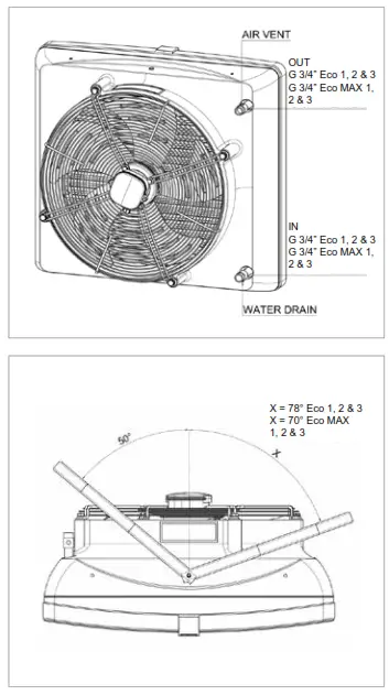 Use flexible connections to allow the heater to be turned to the sides. Depending on the flexible connections, the maximum turn is 70° – for Solano Eco MAX, 78° – for Solano Eco 1, 2 and 3 to both sides. Figure shows maximum angle to one side and 50° to the other with minimal distance left for connections.
Automatic control – installation
A set of automatic control may be used (powered 230V) that consists of the following:
- COMFORT panel – including room thermostat and switch for regulation of 3 speeds of fan. One COMFORT panel may regulate up to
3 pcs of Solano Eco 1, 2 and 3 units or 2 pcs of Solano Eco MAX - 2-way water valve with actuator; valve should be installed on a return stub of the heater
- INTELLIGENT electronic control panel with an automatic speed controller, weekly program and BMS communication.
One INTELLIGENT panel may regulate up to 2 pcs of Solano Eco units or for single Solano Eco MAX - Splitter MULTI 6 – control up to 6 pcs of Solano Eco, Solano Eco MAX units from one COMFORT or INTELLIGENT Panel
The system is ready to start once the connections between the thermostat and the valve actuator are done, 230V power is supplied to the thermostat and the fan’s motor is powered by the revs controller.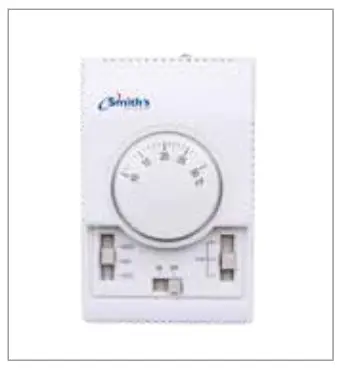
COMFORT panel description
ON/OFF – turning ON/OFF a unit
I-II-III – switch for fan speed regulation
HEAT – thermostat sends signal for valve and actuator and fan, fan turns off when temperature in room is achieved, valve/actuator closes water supply.
FAN – function not active, unit will not operate when FAN switch is selected
COOL – thermostat sends signal only to fan and to the servo of the valve, fan begins operation starting from temperature which is set on thermostat (function used to air mixer Solano MIX or for room ventilation in summer season)
First start
Do all the connections (electrical, water and automatic control), check for tightness of all connections done by an installer and air-release/vent the device then start the device in the following sequence:
- Switch on the mains,
- Set requested speed of fan on revs controller,
- Set requested temperature on thermostat,
The fan operates continuously irrespective of whether the heater’s valve is opened or not.
Turning off
To switch the device off do the following:
- Set minimum temperature on thermostat – after 7 seconds valve will be closed and heating switched off.
- Set main switch to the “0” position (off); fan will be switched off and the thermostat will be off the power.
Operation
The engine and fan used in Solano Eco and Eco MAX units are maintenance-free devices but regular check-ups are advised, especially motor and bearing (fan’s rotor should rotate freely, free from any axial and radial throws and undesired knocks/rattles).
NOTICE!
- In case of any metallic knocks, vibration or increase in sound level check if the fan mounting/fixing does not work loose contact the installer or Smith’s Authorised Service
Maintenance
The heat exchanger requires systematical cleaning all with all dirt/impurities cleaned off. Before the start of the heating period the heat ex-changer is advised to be cleaned with compressed air directed to the air outlets; there is no need for dismantling of the device. Pay special attention when cleaning the exchanger’s fin due to high possibility of damaging them. If fins are bent use a tool specifically designated to carry out such repairs. If the device has not been used for a longer period of time, unplug it before the next use. The heat exchanger is not equipped with any frost protection device. The heat exchanger may be damaged if the room temperature goes below 0°C.
Anti-freeze liquid must be added to the water circulation/system. Anti-freeze liquid must be appropriate for the material the exchanger is made of (copper) as well as other elements of the hydraulic system. The liquid must be diluted with water according to the solution recommended by the anti-freeze manufacturer.
Technical data
Heater Eco 1
| inlet/outlet water temperature | water 50/30 °C | water 60/40 °C | water 70/50 °C | |||||||||||||
| inlet air temperature | °C | 0 | 5 | 10 | 15 | 20 | 0 | 5 | 10 | 15 | 20 | 0 | 5 | 10 | 15 | 20 |
High speed – Air flow 3900 m³/h (speed 3)
| heat output | kW | 8.7 | 7.1 | 5.4 | 3.6 | 1.7 | 12.4 | 10.8 | 9.3 | 7.7 | 6.1 | 16.0 | 14.4 | 12.9 | 11.3 | 9.7 |
| outlet air temperature | °C | 7.3 | 10.5 | 14.2 | 17.8 | 21.3 | 10.2 | 14.4 | 18.5 | 22.7 | 26.9 | 12.8 | 16.9 | 21.2 | 25.3 | 29.4 |
| water flow | m³/h | 0.4 | 0.3 | 0.2 | 0.2 | 0.1 | 0.5 | 0.5 | 0.4 | 0.3 | 0.3 | 0.7 | 0.6 | 0.6 | 0.5 | 0.4 |
| pressure drop | kPa | 2.8 | 1.9 | 1.2 | 0.6 | 0.2 | 4.8 | 3.8 | 2.9 | 2.1 | 1.4 | 7.1 | 5.9 | 4.8 | 3.8 | 2.9 |
Mid speed – Air flow 2500 m³/h (speed 2)
| heat output | kW | 6.7 | 5.5 | 4.2 | 2.1 | 1.5 | 9.7 | 8.5 | 7.2 | 6.0 | 4.7 | 12.5 | 11.3 | 10.0 | 8.8 | 7.6 |
| outlet air temperature | °C | 8.8 | 11.6 | 15.0 | 17.6 | 21.8 | 12.4 | 16.3 | 20.2 | 24.1 | 28.0 | 15.6 | 19.5 | 23.3 | 27.2 | 31.1 |
| water flow | m³/h | 0.3 | 0.2 | 0.2 | 0.1 | 0.1 | 0.4 | 0.4 | 0.3 | 0.3 | 0.2 | 0.5 | 0.5 | 0.4 | 0.4 | 0.3 |
| pressure drop | kPa | 1.8 | 1.2 | 0.8 | 0.2 | 0.1 | 3.1 | 2.4 | 1.9 | 1.3 | 0.9 | 4.6 | 3.8 | 3.1 | 2.5 | 1.9 |
Low speed – Air flow 1850 m³/h (speed 1)
| heat output | kW | 5.6 | 4.5 | 3.4 | 2.0 | 1.4 | 8.1 | 7.1 | 6.1 | 5.0 | 3.9 | 10.5 | 9.5 | 8.4 | 7.4 | 6.4 |
| outlet air temperature | °C | 9.9 | 12.4 | 15.5 | 18.2 | 22.3 | 14.0 | 17.8 | 21.5 | 25.1 | 28.6 | 17.7 | 21.4 | 25.1 | 28.7 | 32.3 |
| water flow | m³/h | 0.3 | 0.2 | 0.2 | 0.1 | 0.1 | 0.4 | 0.3 | 0.3 | 0.2 | 0.2 | 0.5 | 0.4 | 0.4 | 0.3 | 0.3 |
| pressure drop | kPa | 1.3 | 0.9 | 0.5 | 0.2 | 0.1 | 2.3 | 1.8 | 1.4 | 1.0 | 0.6 | 3.4 | 2.8 | 2.3 | 1.8 | 1.4 |
| inlet/outlet water temperature | water 80/60 °C | water 90/70 °C | water 120/90 °C | |||||||||||||
| inlet air temperature | °C | 0 | 5 | 10 | 15 | 20 | 0 | 5 | 10 | 15 | 20 | 0 | 5 | 10 | 15 | 20 |
High speed – Air flow 3900 m³/h (speed 3)
| heat output | kW | 21.1 | 19.4 | 17.6 | 15.9 | 14.2 | 23.0 | 21.4 | 19.7 | 17.9 | 16.1 | 37.9 | 35.9 | 33.9 | 31.9 | 29.9 |
| outlet air temperature | °C | 17.2 | 21.7 | 26.3 | 30.8 | 35.5 | 18.0 | 25.8 | 30.7 | 35.5 | 40.3 | 30.7 | 36.0 | 41.3 | 46.6 | 51.9 |
| water flow | m³/h | 0.8 | 0.8 | 0.7 | 0.6 | 0.6 | 0.8 | 0.8 | 0.7 | 0.7 | 0.6 | 0.9 | 0.8 | 0.8 | 0.7 | 0.7 |
| pressure drop | kPa | 9.7 | 8.4 | 7.1 | 5.9 | 4.8 | 9.7 | 8.7 | 7.7 | 6.8 | 5.9 | 9.4 | 8.5 | 7.7 | 6.9 | 6.1 |
Mid speed – Air flow 2500 m³/h (speed 2)
| heat output | kW | 16.4 | 15.1 | 13.8 | 12.4 | 11.1 | 21.0 | 19.5 | 18.1 | 16.6 | 15.2 | 29.6 | 28.0 | 26.5 | 24.9 | 23.4 |
| outlet air temperature | °C | 20.9 | 25.2 | 29.4 | 33.7 | 38.0 | 25.6 | 30.1 | 34.6 | 39.0 | 43.6 | 37.4 | 42.3 | 47.3 | 52.2 | 57.3 |
| water flow | m³/h | 0.7 | 0.6 | 0.5 | 0.5 | 0.4 | 0.8 | 0.7 | 0.7 | 0.6 | 0.6 | 0.7 | 0.6 | 0.6 | 0.6 | 0.5 |
| pressure drop | kPa | 6.3 | 5.4 | 4.6 | 3.8 | 3.1 | 8.0 | 7.1 | 6.2 | 5.3 | 4.5 | 6.0 | 5.5 | 4.9 | 4.4 | 4.0 |
Low speed – Air flow 1850 m³/h (speed 1)
| heat output | kW | 13.8 | 12.7 | 11.6 | 10.4 | 9.3 | 17.6 | 16.4 | 15.2 | 14.0 | 12.8 | 24.8 | 23.5 | 22.2 | 20.9 | 19.6 |
| outlet air temperature | °C | 23.6 | 27.7 | 31.8 | 35.8 | 39.8 | 29.0 | 33.2 | 37.5 | 41.8 | 45.9 | 42.3 | 47.0 | 51.8 | 56.4 | 61.2 |
| water flow | m³/h | 0.5 | 0.5 | 0.5 | 0.4 | 0.4 | 0.6 | 0.6 | 0.6 | 0.5 | 0.5 | 0.6 | 0.5 | 0.5 | 0.5 | 0.4 |
| pressure drop | kPa | 4.6 | 3.9 | 3.3 | 2.8 | 2.3 | 5.9 | 5.2 | 4.5 | 3.9 | 3.3 | 4.4 | 4.0 | 3.6 | 3.2 | 2.9 |
Heater Eco 2
| inlet/outlet water temperature | water 50/30 °C | water 60/40 °C | water 70/50 °C | |||||||||||||
| inlet air temperature | °C | 0 | 5 | 10 | 15 | 20 | 0 | 5 | 10 | 15 | 20 | 0 | 5 | 10 | 15 | 20 |
High speed – Air flow 3350 m³/h (speed 3)
| heat output | kW | 12.5 | 10.5 | 8.4 | 6.1 | 2.8 | 19.6 | 17.3 | 15.0 | 12.6 | 10.2 | 26.2 | 23.7 | 21.3 | 18.8 | 16.3 |
| outlet air temperature | °C | 10.7 | 14.3 | 16.9 | 19.5 | 21.9 | 16.6 | 19.0 | 21.2 | 23.5 | 25.8 | 22.1 | 24.6 | 27.1 | 29.5 | 32.0 |
| water flow | m³/h | 0.7 | 0.6 | 0.5 | 0.3 | 0.2 | 1.0 | 0.8 | 0.7 | 0.6 | 0.5 | 1.2 | 1.1 | 1.0 | 0.9 | 0.8 |
| pressure drop | kPa | 4.4 | 3.2 | 2.1 | 1.2 | 0.3 | 7.2 | 5.8 | 4.4 | 3.3 | 2.2 | 10.5 | 8.8 | 7.2 | 5.8 | 4.5 |
Mid speed – Air flow 2000 m³/h (speed 2)
| heat output | kW | 9.1 | 7.6 | 6.0 | 4.2 | 2.4 | 14.2 | 12.6 | 10.9 | 9.2 | 7.4 | 19.0 | 17.2 | 15.5 | 13.7 | 11.9 |
| outlet air temperature | °C | 12.9 | 19.4 | 21.4 | 23.0 | 24.5 | 20.2 | 22.1 | 23.9 | 25.8 | 27.7 | 26.9 | 28.9 | 30.9 | 33.0 | 35.0 |
| water flow | m³/h | 0.5 | 0.4 | 0.3 | 0.2 | 0.1 | 0.7 | 0.6 | 0.5 | 0.4 | 0.4 | 0.9 | 0.8 | 0.7 | 0.6 | 0.5 |
| pressure drop | kPa | 2.5 | 1.8 | 1.2 | 0.6 | 0.2 | 4.1 | 3.3 | 2.5 | 1.9 | 1.3 | 5.9 | 4.9 | 4.1 | 3.3 | 2.6 |
Low speed – Air flow 1450 m³/h (speed 1)
| heat output | kW | 7.3 | 6.1 | 4.8 | 2.9 | 2.1 | 11.5 | 10.2 | 8.8 | 7.4 | 6.0 | 15.3 | 13.9 | 12.5 | 11.1 | 9.6 |
| outlet air temperature | °C | 14.4 | 21.0 | 22.5 | 22.6 | 25.5 | 22.5 | 24.1 | 25.8 | 27.3 | 28.8 | 29.9 | 31.7 | 33.5 | 35.2 | 37.0 |
| water flow | m³/h | 0.4 | 0.3 | 0.3 | 0.2 | 0.1 | 0.6 | 0.5 | 0.4 | 0.4 | 0.3 | 0.7 | 0.6 | 0.6 | 0.5 | 0.4 |
| pressure drop | kPa | 1.7 | 1.2 | 0.8 | 0.3 | 0.2 | 2.8 | 2.2 | 1.7 | 1.3 | 0.9 | 4.0 | 3.4 | 2.8 | 2.2 | 1.8 |
| inlet/outlet water temperature | water 80/60 °C | water 90/70 °C | water 120/90 °C | |||||||||||||
| inlet air temperature | °C | 0 | 5 | 10 | 15 | 20 | 0 | 5 | 10 | 15 | 20 | 0 | 5 | 10 | 15 | 20 |
High speed – Air flow 3350 m³/h (speed 3)
| heat output | kW | 32.5 | 30.0 | 27.5 | 24.9 | 22.4 | 39.3 | 36.7 | 34.0 | 31.4 | 28.8 | 53.4 | 50.7 | 48.0 | 45.3 | 42.6 |
| outlet air temperature | °C | 27.2 | 29.7 | 32.2 | 34.8 | 37.3 | 32.4 | 35.0 | 37.6 | 40.2 | 42.7 | 45.0 | 47.6 | 50.4 | 53.1 | 55.9 |
| water flow | m³/h | 1.5 | 1.3 | 1.2 | 1.1 | 1.0 | 1.7 | 1.6 | 1.5 | 1.4 | 1.2 | 1.5 | 1.4 | 1.3 | 1.3 | 1.2 |
| pressure drop | kPa | 14.1 | 12.2 | 10.4 | 8.8 | 7.2 | 18.2 | 16.0 | 14.0 | 12.1 | 10.4 | 13.6 | 12.4 | 11.2 | 10.1 | 9.0 |
Mid speed – Air flow 2000 m³/h (speed 2)
| heat output | kW | 23.5 | 21.7 | 19.9 | 18.1 | 16.3 | 28.4 | 26.5 | 24.6 | 22.7 | 20.9 | 38.6 | 36.7 | 34.8 | 32.8 | 30.9 |
| outlet air temperature | °C | 32.9 | 35.0 | 37.1 | 39.2 | 41.3 | 39.2 | 41.4 | 43.5 | 45.6 | 47.8 | 54.5 | 56.7 | 59.0 | 61.2 | 63.4 |
| water flow | m³/h | 1.1 | 1.0 | 0.9 | 0.8 | 0.7 | 1.2 | 1.1 | 1.1 | 1.0 | 0.9 | 1.1 | 1.0 | 1.0 | 0.9 | 0.9 |
| pressure drop | kPa | 7.9 | 6.8 | 5.8 | 4.9 | 4.1 | 10.1 | 8.9 | 7.8 | 6.8 | 5.8 | 7.6 | 6.9 | 6.3 | 5.7 | 5.1 |
Low speed – Air flow 1450 m³/h (speed 1)
| heat output | kW | 19.0 | 17.5 | 16.1 | 14.6 | 13.2 | 22.9 | 21.4 | 19.9 | 18.4 | 16.9 | 31.2 | 29.6 | 28.1 | 26.5 | 25.0 |
| outlet air temperature | °C | 36.6 | 38.4 | 40.2 | 42.1 | 43.9 | 43.5 | 45.4 | 47.3 | 49.2 | 51.1 | 60.6 | 62.5 | 64.6 | 66.5 | 68.4 |
| water flow | m³/h | 0.8 | 0.8 | 0.7 | 0.7 | 0.6 | 1.0 | 0.9 | 0.9 | 0.8 | 0.7 | 0.9 | 0.8 | 0.8 | 0.7 | 0.7 |
| pressure drop | kPa | 5.4 | 4.7 | 4.0 | 3.4 | 2.8 | 6.9 | 6.1 | 5.3 | 4.6 | 4.0 | 5.2 | 4.7 | 4.3 | 3.9 | 3.5 |
| inlet/outlet water temperature | water 50/30 °C | water 60/40 °C | water 70/50 °C | |||||||||||||
| inlet air temperature | °C | 0 | 5 | 10 | 15 | 20 | 0 | 5 | 10 | 15 | 20 | 0 | 5 | 10 | 15 | 20 |
High speed – Air flow 2950 m³/h (speed 3)
| heat output | kW | 20.0 | 17.0 | 14.0 | 10.8 | 7.2 | 27.9 | 24.8 | 21.7 | 18.6 | 15.3 | 35.3 | 32.1 | 29.0 | 25.8 | 22.6 |
| outlet air temperature | °C | 20.1 | 21.5 | 22.8 | 24.0 | 24.9 | 27.2 | 28.8 | 30.2 | 31.6 | 33.0 | 34.2 | 35.8 | 37.3 | 38.7 | 40.2 |
| water flow | m³/h | 1.0 | 0.9 | 0.7 | 0.5 | 0.4 | 1.3 | 1.2 | 1.0 | 0.9 | 0.7 | 1.7 | 1.5 | 1.4 | 1.2 | 1.1 |
| pressure drop | kPa | 7.9 | 5.9 | 4.1 | 2.6 | 1.3 | 12.5 | 10.1 | 8.0 | 6.0 | 4.3 | 17.8 | 15.0 | 12.5 | 10.1 | 8.0 |
Mid speed – Air flow 1700 m³/h (speed 2)
| heat output | kW | 13.5 | 11.5 | 9.4 | 7.2 | 3.9 | 18.7 | 16.7 | 14.6 | 12.6 | 10.4 | 23.6 | 21.5 | 19.5 | 17.4 | 15.3 |
| outlet air temperature | °C | 23.9 | 24.8 | 25.5 | 26.3 | 27.0 | 32.3 | 33.2 | 34.2 | 35.1 | 35.9 | 40.4 | 41.4 | 42.4 | 43.4 | 44.4 |
| water flow | m³/h | 0.7 | 0.6 | 0.5 | 0.4 | 0.2 | 0.9 | 0.8 | 0.7 | 0.6 | 0.5 | 1.1 | 1.0 | 0.9 | 0.8 | 0.7 |
| pressure drop | kPa | 3.9 | 2.9 | 2.0 | 1.3 | 0.4 | 6.1 | 5.0 | 3.9 | 3.0 | 2.1 | 8.6 | 7.3 | 6.1 | 5.0 | 3.9 |
Low speed – Air flow 1200 m³/h (speed 1)
| heat output | kW | 10.4 | 8.8 | 7.2 | 5.4 | 3.4 | 14.4 | 12.9 | 11.3 | 9.7 | 8.0 | 18.1 | 16.6 | 15.0 | 13.4 | 11.8 | |
| outlet air temperature | °C | 26.1 | 27.9 | 29.6 | 31.1 | 32.3 | 35.2 | 36.0 | 36.6 | 37.1 | 37.6 | 44.0 | 44.7 | 45.5 | 46.2 | 46.9 | |
| water flow | m³/h | 0.5 | 0.4 | 0.4 | 0.3 | 0.2 | 0.7 | 0.6 | 0.5 | 0.5 | 0.4 | 0.9 | 0.8 | 0.7 | 0.6 | 0.6 | |
| pressure drop | kPa | 2.4 | 1.8 | 1.3 | 0.8 | 0.3 | 3.8 | 3.1 | 2.5 | 1.9 | 1.3 | 5.4 | 4.6 | 3.8 | 3.1 | 2.5 |
| inlet/outlet water temperature | water 80/60 °C | water 90/70 °C | water 120/90 °C | |||||||||||||
| inlet air temperature | °C | 0 | 5 | 10 | 15 | 20 | 0 | 5 | 10 | 15 | 20 | 0 | 5 | 10 | 15 | 20 |
High speed – Air flow 2950 m³/h (speed 3)
| heat output | kW | 42.5 | 39.4 | 36.2 | 33.0 | 29.8 | 50.1 | 46.9 | 43.6 | 40.4 | 37.2 | 67.1 | 63.8 | 60.5 | 57.2 | 54.0 |
| outlet air temperature | °C | 41.0 | 42.6 | 44.1 | 45.7 | 47.2 | 47.9 | 49.5 | 51.0 | 52.6 | 54.1 | 63.5 | 65.0 | 66.5 | 68.0 | 69.5 |
| water flow | m³/h | 2.0 | 1.8 | 1.7 | 1.5 | 1.4 | 2.3 | 2.1 | 2.0 | 1.9 | 1.7 | 2.0 | 1.9 | 1.8 | 1.7 | 1.6 |
| pressure drop | kPa | 23.6 | 20.5 | 17.6 | 14.9 | 12.4 | 29.9 | 26.5 | 23.3 | 20.3 | 17.5 | 22.5 | 20.6 | 18.7 | 16.9 | 15.2 |
Mid speed – Air flow 1700 m³/h (speed 2)
| heat output | kW | 28.3 | 26.3 | 24.2 | 22.1 | 20.0 | 33.3 | 31.2 | 29.1 | 27.0 | 24.9 | 44.7 | 42.5 | 40.4 | 38.2 | 36.1 |
| outlet air temperature | °C | 48.3 | 49.3 | 50.4 | 51.4 | 52.4 | 56.2 | 57.3 | 58.4 | 59.4 | 60.5 | 74.6 | 75.6 | 76.7 | 77.7 | 78.7 |
| water flow | m³/h | 1.3 | 1.2 | 1.1 | 1.0 | 0.9 | 1.5 | 1.4 | 1.3 | 1.2 | 1.1 | 1.4 | 1.3 | 1.2 | 1.2 | 1.1 |
| pressure drop | kPa | 11.3 | 9.9 | 8.5 | 7.2 | 6.1 | 14.3 | 12.7 | 11.2 | 9.8 | 8.5 | 10.8 | 9.9 | 9.0 | 8.2 | 7.4 |
Low speed – Air flow 1200 m³/h (speed 1)
| heat output | kW | 21.7 | 20.2 | 18.6 | 17.0 | 15.4 | 25.5 | 23.9 | 22.3 | 20.7 | 19.1 | 34.2 | 32.6 | 31.0 | 29.4 | 27.8 |
| outlet air temperature | °C | 54.2 | 53.3 | 54.0 | 54.8 | 55.5 | 60.4 | 61.1 | 61.9 | 62.7 | 63.4 | 79.6 | 80.4 | 81.2 | 81.9 | 82.7 |
| water flow | m³/h | 1.0 | 0.9 | 0.9 | 0.8 | 0.7 | 1.2 | 1.1 | 1.0 | 0.9 | 0.9 | 1.0 | 1.0 | 0.9 | 0.9 | 0.8 |
| pressure drop | kPa | 7.0 | 6.1 | 5.3 | 4.5 | 3.8 | 8.8 | 7.9 | 6.9 | 6.1 | 5.3 | 6.7 | 6.1 | 5.6 | 5.1 | 4.6 |
Heater Eco MAX 1
| inlet/outlet water temperature | water 50/30 °C | water 60/40 °C | water 70/50 °C | |||||||||||||
| inlet air temperature | °C | 0 | 5 | 10 | 15 | 20 | 0 | 5 | 10 | 15 | 20 | 0 | 5 | 10 | 15 | 20 |
High speed – Air flow 5700 m³/h (speed 3)
| heat output | kW | 24.5 | 20.5 | 16.5 | 12.3 | 7.5 | 32.2 | 28.3 | 24.5 | 20.6 | 16.7 | 39.7 | 35.9 | 32.0 | 28.3 | 24.5 |
| outlet air temperature | °C | 13.7 | 16.8 | 19.8 | 22.7 | 25.0 | 18.0 | 21.1 | 24.2 | 27.3 | 30.2 | 22.3 | 25.5 | 28.6 | 31.7 | 34.8 |
| water flow | m³/h | 0.8 | 0.6 | 0.5 | 0.4 | 0.2 | 1.0 | 0.9 | 0.8 | 0.7 | 0.5 | 1.3 | 1.2 | 1.0 | 0.9 | 0.8 |
| pressure drop | kPa | 3.5 | 2.5 | 1.7 | 0.9 | 0.3 | 5.8 | 4.6 | 3.5 | 2.6 | 1.8 | 8.4 | 7.0 | 5.7 | 4.5 | 3.5 |
Mid speed – Air flow 3900 m³/h (speed 2)
| heat output | kW | 19.6 | 16.4 | 13.1 | 9.7 | 4.4 | 25.7 | 22.6 | 19.5 | 16.5 | 13.4 | 31.7 | 28.6 | 25.6 | 22.6 | 19.6 |
| outlet air temperature | °C | 15.9 | 18.6 | 21.3 | 23.7 | 24.4 | 20.9 | 23.7 | 26.6 | 29.2 | 31.8 | 25.9 | 28.8 | 31.6 | 34.5 | 37.2 |
| water flow | m³/h | 0.9 | 0.8 | 0.6 | 0.5 | 0.2 | 1.3 | 1.1 | 1.0 | 0.8 | 0.7 | 1.6 | 1.4 | 1.3 | 1.1 | 1.0 |
| pressure drop | kPa | 5.1 | 3.7 | 2.5 | 1.4 | 0.4 | 8.5 | 6.7 | 5.2 | 3.8 | 2.6 | 12.3 | 10.2 | 8.3 | 6.7 | 5.1 |
Low speed – Air flow 2800 m³/h (speed 1)
| heat output | kW | 15.9 | 13.3 | 10.6 | 7.7 | 4.0 | 20.9 | 18.4 | 15.9 | 13.4 | 10.8 | 25.6 | 23.2 | 20.7 | 18.3 | 15.9 |
| outlet air temperature | °C | 18.0 | 20.4 | 22.7 | 24.5 | 25.4 | 23.6 | 26.2 | 28.7 | 31.0 | 33.3 | 29.2 | 31.9 | 34.5 | 37.0 | 39.4 |
| water flow | m³/h | 0.8 | 0.6 | 0.5 | 0.4 | 0.2 | 1.0 | 0.9 | 0.8 | 0.7 | 0.5 | 1.3 | 1.2 | 1.0 | 0.9 | 0.8 |
| pressure drop | kPa | 3.5 | 2.5 | 1.7 | 0.9 | 0.3 | 5.8 | 4.6 | 3.5 | 2.6 | 1.8 | 8.4 | 7.0 | 5.7 | 4.5 | 3.5 |
| inlet/outlet water temperature | water 80/60 °C | water 90/70 °C | water 120/90 °C | |||||||||||||
| inlet air temperature | °C | 0 | 5 | 10 | 15 | 20 | 0 | 5 | 10 | 15 | 20 | 0 | 5 | 10 | 15 | 20 |
High speed – Air flow 5700 m³/h (speed 3)
| heat output | kW | 47.5 | 43.6 | 39.8 | 36.0 | 32.2 | 55.0 | 51.1 | 47.2 | 43.4 | 39.6 | 72.4 | 68.5 | 64.5 | 60.6 | 56.8 |
| outlet air temperature | °C | 26.0 | 29.2 | 32.3 | 35.4 | 38.4 | 30.1 | 33.3 | 36.4 | 39.5 | 42.6 | 39.3 | 42.6 | 45.9 | 49.1 | 52.2 |
| water flow | m³/h | 1.5 | 1.4 | 1.3 | 1.2 | 1.0 | 1.8 | 1.7 | 1.5 | 1.4 | 1.3 | 1.6 | 1.5 | 1.4 | 1.3 | 1.3 |
| pressure drop | kPa | 11.3 | 9.7 | 8.2 | 6.8 | 5.6 | 14.5 | 12.7 | 11.0 | 9.4 | 8.0 | 10.9 | 9.8 | 8.8 | 7.9 | 7.0 |
Mid speed – Air flow 3900 m³/h (speed 2)
| heat output | kW | 37.8 | 34.7 | 31.7 | 28.7 | 25.7 | 43.7 | 40.6 | 37.6 | 34.5 | 31.5 | 57.4 | 54.3 | 51.1 | 48.0 | 45.0 |
| outlet air temperature | °C | 30.2 | 33.1 | 36.0 | 38.7 | 41.5 | 34.9 | 37.8 | 40.7 | 43.5 | 46.3 | 45.8 | 48.8 | 51.9 | 54.8 | 57.7 |
| water flow | m³/h | 1.9 | 1.8 | 1.6 | 1.4 | 1.3 | 2.2 | 2.1 | 1.9 | 1.8 | 1.6 | 2.0 | 1.9 | 1.8 | 1.7 | 1.5 |
| pressure drop | kPa | 16.6 | 14.2 | 12.0 | 10.0 | 8.2 | 21.4 | 18.7 | 16.2 | 13.9 | 11.8 | 16.1 | 14.5 | 13.0 | 11.6 | 10.3 |
Low speed – Air flow 2800 m³/h (speed 1)
| heat output | kW | 30.6 | 28.1 | 25.6 | 23.2 | 20.8 | 35.3 | 32.8 | 30.4 | 27.9 | 25.5 | 46.5 | 43.9 | 41.3 | 38.9 | 36.4 |
| outlet air temperature | °C | 34.0 | 36.8 | 39.3 | 41.8 | 44.2 | 39.3 | 42.0 | 44.6 | 47.1 | 49.7 | 51.5 | 54.5 | 57.2 | 59.9 | 62.5 |
| water flow | m³/h | 1.5 | 1.4 | 1.3 | 1.2 | 1.0 | 1.8 | 1.7 | 1.5 | 1.4 | 1.3 | 1.6 | 1.5 | 1.4 | 1.3 | 1.3 |
| pressure drop | kPa | 11.3 | 9.7 | 8.2 | 6.8 | 5.6 | 14.5 | 12.7 | 11.0 | 9.4 | 8.0 | 10.9 | 9.8 | 8.8 | 7.9 | 7.0 |
| inlet/outlet water temperature | water 50/30 °C | water 60/40 °C | water 70/50 °C | |||||||||||||
| inlet air temperature | °C | 0 | 5 | 10 | 15 | 20 | 0 | 5 | 10 | 15 | 20 | 0 | 5 | 10 | 15 | 20 |
High speed – Air flow 5600 m³/h (speed 3)
| heat output | kW | 31.9 | 27.0 | 22.2 | 17.2 | 11.8 | 41.6 | 36.8 | 32.0 | 27.3 | 22.5 | 53.0 | 48.0 | 43.1 | 38.2 | 33.3 |
| outlet air temperature | °C | 20.9 | 24.8 | 28.4 | 31.9 | 35.1 | 27.3 | 31.4 | 35.5 | 39.3 | 43.2 | 35.0 | 39.3 | 43.3 | 47.4 | 51.3 |
| water flow | m³/h | 1.4 | 1.2 | 0.9 | 0.7 | 0.5 | 1.7 | 1.5 | 1.3 | 1.1 | 0.9 | 2.2 | 2.0 | 1.8 | 1.6 | 1.4 |
| pressure drop | kPa | 10.5 | 7.8 | 5.4 | 3.4 | 1.7 | 15.9 | 12.7 | 9.9 | 7.4 | 5.2 | 23.7 | 19.8 | 16.3 | 13.1 | 10.2 |
Mid speed – Air flow 3800 m³/h (speed 2)
| heat output | kW | 25.3 | 21.4 | 17.5 | 13.5 | 9.0 | 32.9 | 29.1 | 25.3 | 21.6 | 17.8 | 41.9 | 37.9 | 34.0 | 30.2 | 26.4 |
| outlet air temperature | °C | 24.2 | 27.6 | 30.8 | 33.8 | 36.0 | 31.6 | 35.3 | 38.9 | 42.3 | 45.6 | 40.4 | 44.3 | 47.9 | 51.5 | 55.0 |
| water flow | m³/h | 1.1 | 0.9 | 0.7 | 0.6 | 0.4 | 1.4 | 1.2 | 1.1 | 0.9 | 0.7 | 1.7 | 1.6 | 1.4 | 1.3 | 1.1 |
| pressure drop | kPa | 6.9 | 5.1 | 3.6 | 2.2 | 1.1 | 10.4 | 8.3 | 6.5 | 4.8 | 3.4 | 15.4 | 12.9 | 10.6 | 8.5 | 6.7 |
Low speed – Air flow 2750 m³/h (speed 1)
| heat output | kW | 20.1 | 17.3 | 14.1 | 10.8 | 6.1 | 26.5 | 23.5 | 20.4 | 17.4 | 14.4 | 33.7 | 30.5 | 27.4 | 24.3 | 21.2 |
| outlet air temperature | °C | 27.2 | 30.1 | 32.8 | 35.2 | 35.5 | 35.5 | 38.8 | 41.9 | 45.1 | 47.8 | 45.3 | 48.8 | 52.1 | 55.1 | 58.2 |
| water flow | m³/h | 0.9 | 0.7 | 0.6 | 0.5 | 0.3 | 1.1 | 1.0 | 0.9 | 0.7 | 0.6 | 1.4 | 1.3 | 1.1 | 1.0 | 0.9 |
| pressure drop | kPa | 4.7 | 3.5 | 2.4 | 1.5 | 0.5 | 7.0 | 5.6 | 4.4 | 3.3 | 2.3 | 10.4 | 8.7 | 7.2 | 5.8 | 4.5 |
| inlet/outlet water temperature | water 80/60 °C | water 90/70 °C | water 120/90 °C | |||||||||||||
| inlet air temperature | °C | 0 | 5 | 10 | 15 | 20 | 0 | 5 | 10 | 15 | 20 | 0 | 5 | 10 | 15 | 20 |
High speed – Air flow 5600 m³/h (speed 3)
| heat output | kW | 61.9 | 57.0 | 52.1 | 47.3 | 42.5 | 74.2 | 69.0 | 63.9 | 58.9 | 53.9 | 96.6 | 91.4 | 86.3 | 81.2 | 76.2 |
| outlet air temperature | °C | 41.0 | 45.5 | 49.9 | 54.1 | 58.2 | 49.1 | 53.5 | 57.9 | 62.2 | 66.4 | 63.2 | 68.1 | 72.6 | 77.2 | 81.8 |
| water flow | m³/h | 2.6 | 2.4 | 2.2 | 2.0 | 1.8 | 3.1 | 2.8 | 2.6 | 2.4 | 2.2 | 2.6 | 2.5 | 2.4 | 2.2 | 2.1 |
| pressure drop | kPa | 30.1 | 25.9 | 22.0 | 18.4 | 15.2 | 40.3 | 35.3 | 30.7 | 26.5 | 22.5 | 28.9 | 26.1 | 23.5 | 21.0 | 18.7 |
Mid speed – Air flow 3800 m³/h (speed 2)
| heat output | kW | 48.9 | 45.0 | 41.1 | 37.3 | 33.5 | 58.4 | 54.3 | 50.3 | 46.4 | 42.4 | 76.2 | 72.1 | 68.0 | 64.0 | 60.0 |
| outlet air temperature | °C | 47.4 | 51.5 | 55.4 | 59.2 | 62.9 | 56.5 | 60.6 | 64.6 | 68.4 | 72.1 | 72.9 | 77.4 | 81.7 | 85.8 | 89.8 |
| water flow | m³/h | 2.0 | 1.9 | 1.7 | 1.5 | 1.4 | 2.4 | 2.2 | 2.1 | 1.9 | 1.8 | 2.1 | 2.0 | 1.9 | 1.7 | 1.6 |
| pressure drop | kPa | 19.6 | 16.8 | 14.3 | 12.0 | 9.9 | 26.1 | 22.9 | 19.9 | 17.1 | 14.6 | 18.7 | 16.9 | 15.2 | 13.6 | 12.1 |
Low speed – Air flow 2750 m³/h (speed 1)
| heat output | kW | 39.3 | 36.2 | 33.1 | 30.0 | 27.0 | 46.9 | 43.7 | 40.4 | 37.2 | 34.1 | 61.3 | 58.0 | 54.7 | 51.4 | 48.2 |
| outlet air temperature | °C | 53.2 | 56.8 | 60.3 | 63.7 | 67.1 | 63.1 | 66.8 | 70.5 | 73.9 | 77.3 | 81.7 | 85.8 | 89.7 | 93.5 | 97.1 |
| water flow | m³/h | 1.6 | 1.5 | 1.4 | 1.2 | 1.1 | 1.9 | 1.8 | 1.7 | 1.5 | 1.4 | 1.7 | 1.6 | 1.5 | 1.4 | 1.3 |
| pressure drop | kPa | 13.2 | 11.3 | 9.6 | 8.1 | 6.7 | 17.5 | 15.3 | 13.3 | 11.5 | 9.8 | 12.6 | 11.4 | 10.2 | 9.2 | 8.1 |
Heater Eco MAX 3
| inlet/outlet water temperature | water 50/30 °C | water 60/40 °C | water 70/50 °C | |||||||||||||
| inlet air temperature | °C | 0 | 5 | 10 | 15 | 20 | 0 | 5 | 10 | 15 | 20 | 0 | 5 | 10 | 15 | 20 |
High speed – Air flow 5100 m³/h (speed 3)
| heat output | kW | 42.1 | 35.7 | 29.3 | 22.9 | 16.0 | 54.1 | 47.9 | 41.7 | 35.5 | 29.3 | 68.3 | 61.9 | 55.5 | 49.2 | 42.9 |
| outlet air temperature | °C | 26.9 | 29.8 | 32.6 | 35.3 | 37.6 | 34.7 | 38.1 | 41.2 | 44.3 | 47.1 | 44.1 | 47.5 | 50.6 | 53.8 | 56.8 |
| water flow | m³/h | 1.6 | 1.4 | 1.1 | 0.9 | 0.6 | 2.1 | 1.8 | 1.6 | 1.4 | 1.1 | 2.6 | 2.4 | 2.1 | 1.9 | 1.6 |
| pressure drop | kPa | 14.3 | 10.7 | 7.5 | 4.8 | 2.5 | 21.6 | 17.3 | 13.5 | 10.1 | 7.2 | 32.1 | 26.8 | 22.0 | 17.7 | 13.8 |
Mid speed – Air flow 3400 m³/h (speed 2)
| heat output | kW | 32.3 | 27.4 | 22.5 | 17.5 | 12.1 | 41.4 | 36.7 | 32.0 | 27.3 | 22.5 | 52.2 | 47.2 | 42.4 | 37.6 | 32.9 |
| outlet air temperature | °C | 30.9 | 33.3 | 35.6 | 37.6 | 39.0 | 39.8 | 42.7 | 45.4 | 47.8 | 50.2 | 50.5 | 53.4 | 56.1 | 58.7 | 61.1 |
| water flow | m³/h | 1.2 | 1.1 | 0.9 | 0.7 | 0.5 | 1.6 | 1.4 | 1.2 | 1.0 | 0.9 | 2.0 | 1.8 | 1.6 | 1.4 | 1.3 |
| pressure drop | kPa | 8.9 | 6.6 | 4.6 | 2.9 | 1.5 | 13.3 | 10.7 | 8.3 | 6.3 | 4.4 | 19.6 | 16.4 | 13.5 | 10.9 | 8.5 |
Low speed – Air flow 2400 m³/h (speed 1)
| heat output | kW | 25.3 | 21.5 | 17.6 | 13.6 | 9.0 | 32.4 | 28.7 | 25.0 | 21.4 | 17.7 | 40.7 | 36.9 | 33.1 | 29.4 | 25.7 | |
| outlet air temperature | °C | 34.4 | 36.4 | 38.1 | 39.4 | 39.7 | 44.4 | 46.7 | 49.0 | 51.0 | 52.8 | 56.1 | 58.4 | 60.7 | 62.9 | 64.9 | |
| water flow | m³/h | 1.0 | 0.8 | 0.7 | 0.5 | 0.3 | 1.2 | 1.1 | 1.0 | 0.8 | 0.7 | 1.6 | 1.4 | 1.3 | 1.1 | 1.0 | |
| pressure drop | kPa | 5.7 | 4.2 | 3.0 | 1.9 | 0.9 | 8.6 | 6.9 | 5.4 | 4.0 | 2.9 | 12.5 | 10.5 | 8.6 | 6.9 | 5.4 |
| inlet/outlet water temperature | water 80/60 °C | water 90/70 °C | water 120/90 °C | |||||||||||||
| inlet air temperature | °C | 0 | 5 | 10 | 15 | 20 | 0 | 5 | 10 | 15 | 20 | 0 | 5 | 10 | 15 | 20 |
High speed – Air flow 5100 m³/h (speed 3)
| heat output | kW | 79.5 | 73.1 | 66.8 | 60.6 | 54.4 | 93.9 | 87.3 | 80.8 | 74.4 | 68.0 | 121.6 | 115.0 | 108.4 | 101.9 | 95.5 |
| outlet air temperature | °C | 51.0 | 54.5 | 57.9 | 61.2 | 64.5 | 60.1 | 63.6 | 67.0 | 70.4 | 73.5 | 78.0 | 81.8 | 85.5 | 89.2 | 92.6 |
| water flow | m³/h | 3.0 | 2.8 | 2.6 | 2.3 | 2.1 | 3.6 | 3.4 | 3.1 | 2.9 | 2.6 | 3.1 | 3.0 | 2.8 | 2.6 | 2.5 |
| pressure drop | kPa | 40.8 | 35.1 | 29.8 | 24.9 | 20.5 | 54.3 | 47.5 | 41.3 | 35.5 | 30.2 | 39.2 | 35.4 | 31.8 | 28.4 | 25.2 |
Mid speed – Air flow 3400 m³/h (speed 2)
| heat output | kW | 60.6 | 55.8 | 51.0 | 46.2 | 41.5 | 71.5 | 66.4 | 61.5 | 56.6 | 51.7 | 92.8 | 87.7 | 82.6 | 77.7 | 72.8 |
| outlet air temperature | °C | 58.3 | 61.3 | 64.3 | 67.0 | 69.8 | 68.5 | 71.6 | 74.5 | 77.3 | 80.0 | 89.1 | 92.5 | 95.8 | 98.9 | 101.9 |
| water flow | m³/h | 2.3 | 2.1 | 1.9 | 1.8 | 1.6 | 2.7 | 2.6 | 2.4 | 2.2 | 2.0 | 2.4 | 2.3 | 2.1 | 2.0 | 1.9 |
| pressure drop | kPa | 25.0 | 21.4 | 18.2 | 15.3 | 12.6 | 33.0 | 28.9 | 25.1 | 21.6 | 18.3 | 23.9 | 21.6 | 19.4 | 17.3 | 15.4 |
Low speed – Air flow 2400 m³/h (speed 1)
| heat output | kW | 47.3 | 43.5 | 39.7 | 36.1 | 32.4 | 55.6 | 51.6 | 47.8 | 44.0 | 40.2 | 72.3 | 68.3 | 64.4 | 60.5 | 56.7 |
| outlet air temperature | °C | 64.6 | 67.3 | 69.8 | 72.2 | 74.4 | 75.8 | 78.4 | 81.0 | 83.4 | 85.6 | 98.8 | 101.8 | 104.7 | 107.3 | 109.9 |
| water flow | m³/h | 1.8 | 1.7 | 1.5 | 1.4 | 1.2 | 2.1 | 2.0 | 1.8 | 1.7 | 1.5 | 1.9 | 1.8 | 1.7 | 1.6 | 1.5 |
| pressure drop | kPa | 15.9 | 13.6 | 11.6 | 9.7 | 8.0 | 20.9 | 18.3 | 15.9 | 13.6 | 11.6 | 15.2 | 13.7 | 12.3 | 11.0 | 9.7 |
Electrical connection diagrams
13.1. Connecting Solano units with no automatic control
* The unit set does not consist of: a master switch, a fuse, a feeding cable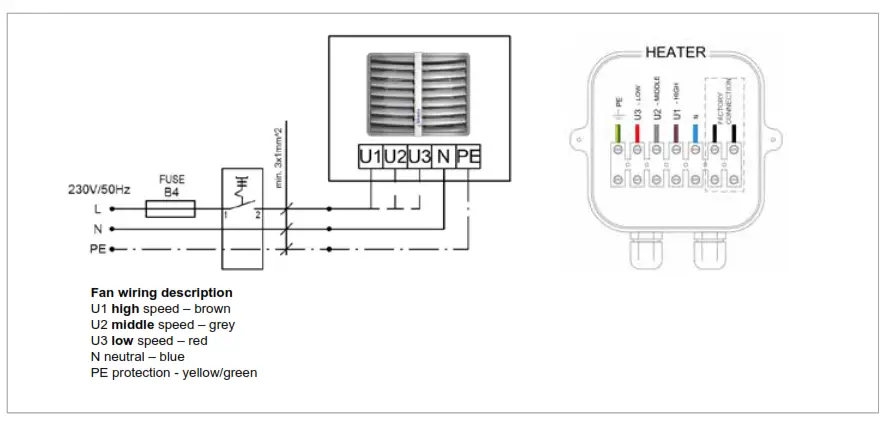
13.2. Connecting severalSolano units with COMFORT panel, valves and actuators
One COMFORT panel may regulate up to:
- 3 pcs of Solano Eco 1, 2 or 3
- 2 pcs of Solano MAX
- The unit set does not consist of: a master switch, a fuse, a feeding cable
HEAT – thermostat sends signal for valve/actuator and fan, fan turns off when temperature in room is achieved, valve/actuator closes water supply.
FAN – function not active, unit will not operate when FAN switch is selected
COOL – thermostat sends signal only to fan and the servo of the valve, fan begins operation starting from temperature which is set on thermostat (function used to air mixer Salano MIX or for room ventilation in summer season)
Attention! You can use additional jumper on the contacts 4-5 of COMFORT Panel, in this case you may only use function of changing speed of fan I-II-IIl and ON/OFF. The thermostat and switches HEAT/FAN/CCOL remain not active.
Additional jumper on terminals 4-5 might be applied when for ex different (supplied by user) thermostat is used to control the system.
In that case:
– motor would be working on set speed
– thermostat open/close the servo of the valve depending on set temperature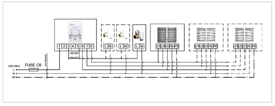
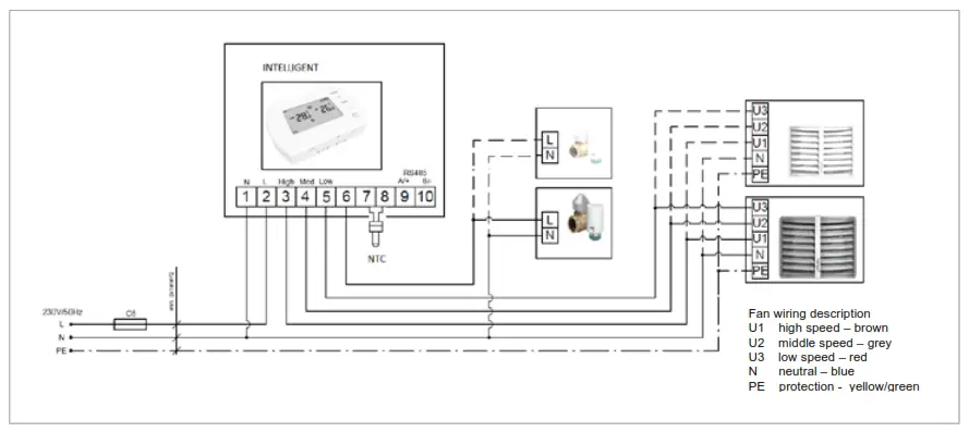
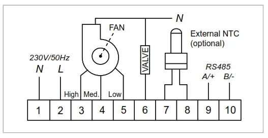
13.3. Connecting Solano units with panel INTELLIGENT.
Panel Intelligent controls actuators/valves and automatically regulates fans’ speed depending on the required room temperature.
Fans speed changes automatically for lower rate, when temperature in a room gets closer to desired one.
Additional functions – weekly thermostat, availability of BMS communication signals Possibility to connect outside temperature sensor NTC, supplied with cable lenght 5 m, max cable length 20 m.
One INTELLIGENT panel may regulate:
- up to 2 pcs of Solane Eco.
- For Solano Eco MAX only 1 pcs
- The unit set does not consist of: a master switch, a fuse, a feeding cable

13.4. Splitter MULTI 6 – control up to 6 pieces of Solano Eco/Solano Eco MAX from one COMFORT or INTELLIGENT Panel
MULTI 6 Splitter allows to connect and control more fan heaters (up to 6 pcs.) and valves with actuators (up to 6 pcs.). Control of fans and valves is done using COMFORT or INTELLIGENT panel.
To connect more than 6 fans and valves, it is possible to connect Splitter MULTI 6 with each other (maximum extension of up to 10 MULTI 6 splitters). In such case, in the first Splitter MULTI 6 there should be connector DS-N left open, in other Splitters MULTI 6 (2.10) connector DS-N must be closed.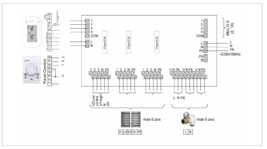
14. Panel intelligent – programmable controller manual Panel Intelligent controls actuators/valves and automatically regulates fan’s speed depending on the required room temperature. The lower temperature in the room the higher air output is set. Fans speed changes automatically for lower rate, when temperature in a room gets closer to desired one.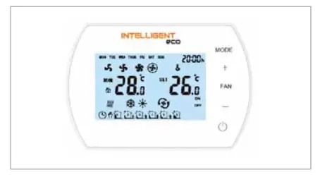
Functions
Panel INTELLINGENT is designed for the Smith’s products
- Weekly thermostat (5/1/1 days)
- Automatic or manual 3-step fan speed adjustment.
- Control room temperature (by opening/closing the vale, or by adjusting air volume automatically).
- Antifreeze mode- protection against dropping room temperature be-low critical level +5/-15°C.
- Possibility to connect external NTC temperature sensor.
- BMS communication by MODBUS protocol
Panel description.
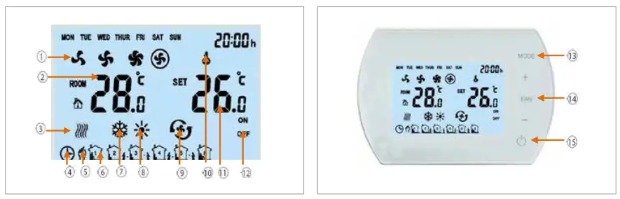
| 1. Fan Speed: LOW, MED, HI and AUTO 2. ROOM TEMP or NTC EXTERNAL SENSOR TEMP 3. Anti-freeze indication 4. Automatic programmable mode Press shortly to select manual or automatic mode | 8. Heating mode 9. Ventilation mode 15. ON/OFF INTELLIGENT Panel 10. Buttons lock 11. SET TEMP. (desired room temperature) (measured temperature) 12. ON/OFF status time zones 13. MODE 14. FAN Press shortly and select fan speed: Low, Med, High or Auto |
Technical parameters
| 1 | Power supply | 230VAC/50Hz |
| 2 | Temperature setting range | 5°C 40°C |
| 3 | Temperature working range | -10°C 60°C |
| 4 | IP class | 20 |
| 5 | Temperature sensor | Internal/external NTC (optional) |
![]() WARNING!
WARNING!
RISK OF ELECRICAL SHOCK. Disconnect power supply before making any electrical connections. Contact with components carrying hazardous voltage can cause electrical shock and may result in severe personal injury
Dimensions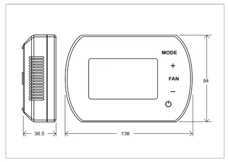
Setting menu
When Panel Intelligent is switched off, press and hold MODE for 5 seconds
To change option use MODE button
To change value use +/- buttons.
| Setting menu | Option | Value |
| 1 | Temperature calibration | –9°C ~ +9°C |
| 2 | Fan status | C1: Thermostatic mode | C2: Continuous mode |
| 3 | Temperature sensor | 0: Internal Sensor | 1: External Sensor NTC (optional) |
| 4 | Antifreeze | 0: Off | 1: On |
| 5 | Antifreeze range | +5°C ~ +10°C |
| 6 | BMS speed | 0-2400 / 1-9600 / 2-19200 |
| 7 | Modbus ID | 1~247 (01~F7) |
Button lock/unlock![]()
To LOCK buttons press and hold + and then – and hold both of them for 5 seconds To UNLOCK buttons press and hold + and then – and hold both of them for 5 seconds.
Press MODE
Change on manual mode![]() or automatic mode
or automatic mode![]()
Hold MODE for 5 seconds
zilt Change to cool mode ![]() heating mode
heating mode![]() ‘IC ventilation
‘IC ventilation![]()
Press FAN
Change the fan speed low ![]() medium
medium ![]() high
high ![]() automatic
automatic![]()
Hold FAN for 5 seconds
Manual callendar programming Monday – Friday, Saturday, Sunday 6 settings per day
BMS Functions
- Setting/Reading work parameters Work/Stop conditions
- Weekly program
- Temperature
- Fan speed
- Heating, ventilation, cool mode Antifreeze mode
| No. | Setting | Parameters |
| 1 | Working Mode | RS485 Semi-duplex; PC or main controller is master; thermostat is slave |
| 2 | Interface | A(+),B(-), 2 wires |
| 3 | Baud Rate | 0-2400 / 1-9600 / 2-19200 |
| 4 | Byte | 9 bits in total: 8 data bit + 1 stop bit |
| 5 | Modbus | RTU Mode |
| 6 | Transmission | RTU (Remote Terminal Unit) format (please refer to MOBUS instruction) |
| 7 | Thermostat address | 1-247: (0 is broadcast address and stand for all thermostat without response) |
Registering your product
Thank you for purchasing a Smith’s product. It has been designed and manufactured to the highest quality standards to ensure it gives you efficient and trouble-free service for many years. We are committed to achieving the highest standards and our faith is supported by a free parts and labour guarantee with every product.
For more information on the warranty period for this product please visit our website smithsep.co.uk/product-registration/ This gives you the peace of mind that in the unlikely event of product failure, we will repair or replace the product completely free of charge providing the product has been installed, used and maintained in accordance with the instructions. Your statutory rights are not affected by this warranty.
It is important to register as soon as possible online at: smithsep.co.uk/product-registration/.
This will ensure you will receive prompt and efficient service if your product requires attention within the warranty period. If you do not register your product, you will be required to produce proof of purchase prior to receiving service.
For more details please visit our website: SmithsEP.co.uk
 https://smithsep.co.uk/2019-form/
Disposal
As part of the policy of continuous product improvement, Smith’s Environmental Products LTD reserves the right to alter specification without prior notice.
Products with this symbol (crossed out wheelie bin) cannot be disposed as household waste. Old electrical and electronic equipment must be recycled at a facility capable of handling these products and their waste by-products. If you are purchasing replacement equipment your retailer may offer a ‘take back’ scheme, or will be able to give details of the nearest approved authorised treatment facility. Proper recycling and waste disposal will help conserve resources whilst preventing detrimental effects on our health and the environment. WEEE Registered Code: WEE/ED0093VW

After sales and spares
If you experience any problems with the use of your product, please contact our after-sales office +44 (0) 1245 324560.
For product information, customer services or sales support call us on +44 (0) 1245 324900
For the Republic of Ireland, contact MT Agencies on 01 864 3363
Sales: [email protected]
General information: [email protected]
Smith’s Environmental Products Ltd
Blackall Industrial Estate, South Woodham Ferrers, Chelmsford, Essex CM3 5UW
SmithsEP.co.uk
@SmithsEP_UK
#ThinkSmiths
Happy to help
Smith’s Environmental Products Ltd is one of the leading manufacturers of heating and cooling products in the UK. We are committed to achieving the highest standards and
our faith is supported by a free parts and labour guarantee with every product (see our website for more information). Our customer service is second to none and we are appy to offer any help and guidance that you might need.
Stockists
All products are available nationally from Builders’ Merchants, Plumbers’ Merchants, Heating Equipment Distributors and Kitchen Equipment Distributors. In the event of difficulty, please contact us or visit our website SmithsEP.co.uk for details of your nearest stockist. Information and advice
Full technical specifications and list prices is available to download from our website or in hard copy from our office. Also available on our website are price lists, individual product data sheets, installation & user guides, where to buy, who to contact and a media centre. Alternatively contact our office 9.00am to 5.00pm Monday to Friday.
As part our commitment to continuous improvement Smith’s Environmental Products may change the specifications of its products without prior notification or public announcement. All descriptions, illustrations, drawings and specifications in this publication present only general particulars and shall not form part of any contract. All dimensions are in mm unless otherwise stated. Please visit the website for the most up to date information.
To view the full product information download the datasheet at: www.SmithsEP.co.uk
For product information, customer services or sales support call us on +44 (0) 1245 324900
For the Republic of Ireland, contact MT Agencies on 01 864 3363
Sales: [email protected]
General information: [email protected]
Smith’s Environmental Products Ltd
Blackall Industrial Estate, South Woodham Ferrers,
Chelmsford, Essex CM3 5UW
SmithsEP.co.uk
@SmithsEP_UK
#ThinkSmiths
Issue 002 | November 2022
Smith’s, providing comfort for the built environment


