TROJAN GP-2000A Automatic Grinder and Polisher User Manual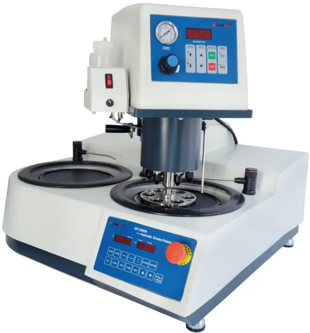
Product Description
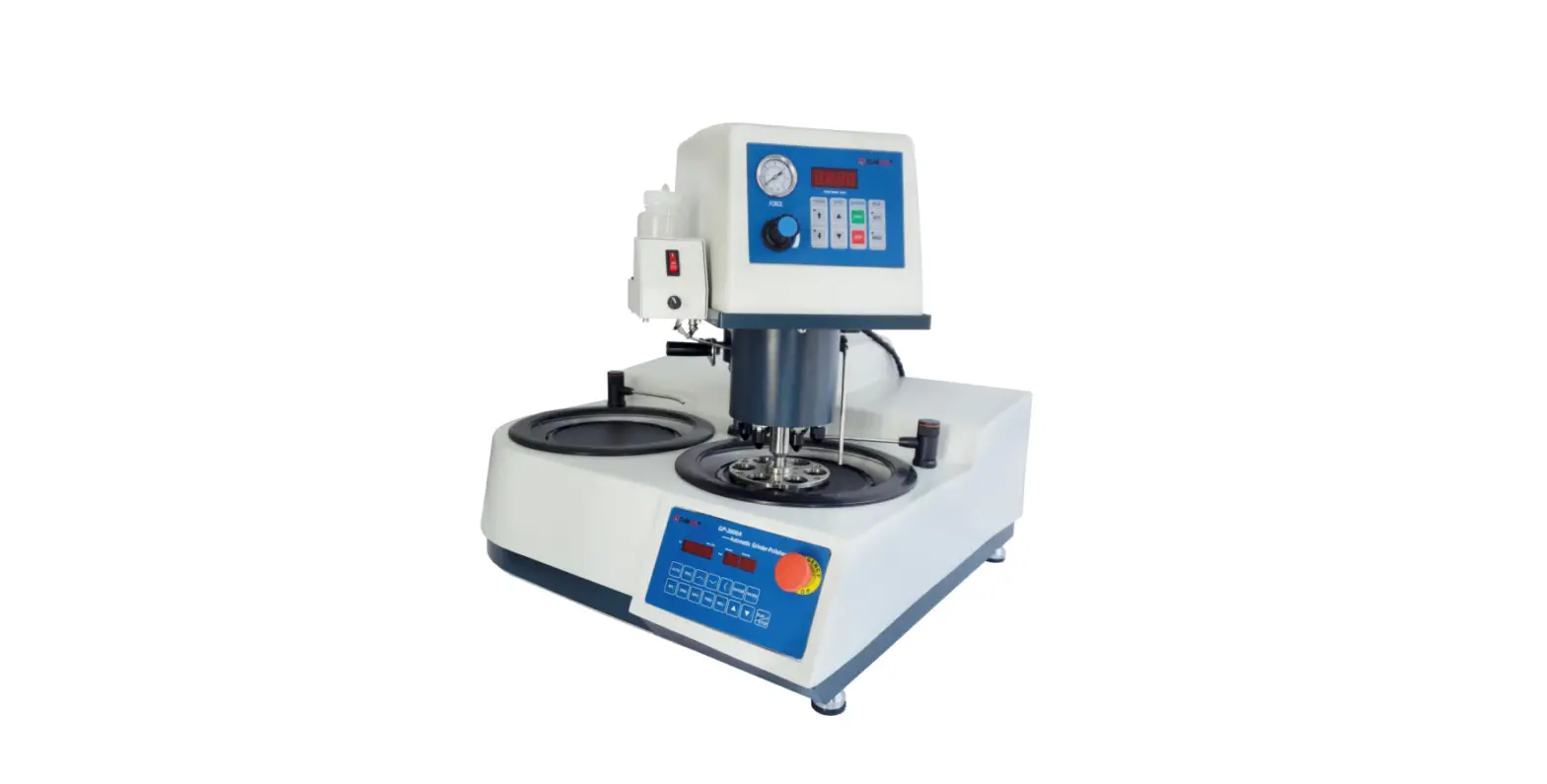
The GP-2000A is a variable speed polishing head (0-200 rpm) for use with the grinding/ polishing base machine for automated metallographic specimen preparation. It can also run either automatically with the polishing base or in a manual mode with independent control.
Technical Specifications
- Electrical specifications: 110V single-phase ,60 Hz
- Number of specimens: 1-6 samples (less than 1-1/2inch diameter). 1-3 samples (2-inch diameter)
- Diameter of specimens: 1-1/4 inch
- Force application: Individual piston
- Force adjustment: 0.1~0.5MPa (with an air pressure regulating valve)
- Head motor power: 125 W
- Base motor power: 750 W
- Base working wheel: 10 inch
- Head speed: 0 to 200 rpm variable speed
- Base wheel speed: 20 to 1000 rpm variable speed
- Weight: Approx. 85 kg (187LBs)
- Dimensions (WxHxD): Approx. 27.5 inch x 29.5 inch x 27.5 inch (700 mm x 750 mm x 700 mm)
Features and Benefits
The GP-2000A is equipped with a 125 W variable 0-200 rpm speed motor. The drive mechanism is connected to the motor via a maintenance-free anti-slip polychain.
The GP-2000A also has a lubricant dispenser in addition to a high flow water valve for hands free wet grinding with abrasive papers and lubrication for polishing.
In addition, the GP-2000A can be operated either automatically or independently of the polishing base.
Installation
Install unit carefully! The GP-2000A should be placed on a flat stable surface. Requires air, water supply, drain and electrical connections. After connecting air, water, drain and electrical supplies the system is ready for operation by activating the main power switches on both the polisher and head for automatic operation.
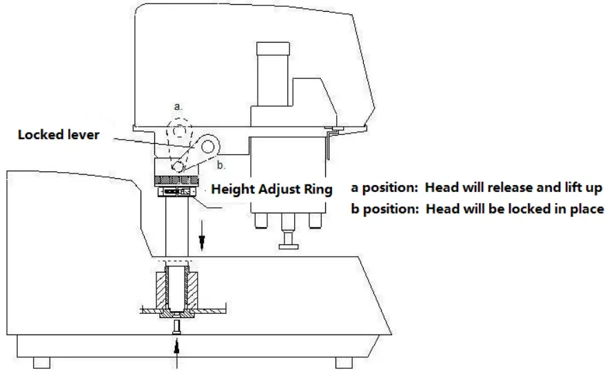
After connecting air, switch the locked lever to “a” position, the head will lift up, then you can swing the head to the left or right side. Move the lever slightly away from “a” position, the head will fall down. Continue to push the lever to “b” position by force, then the head will be locked. In order to achieve better effects, the height from the sample holder to the working wheel should be around 2mm. If the distance is not good, lift up the head, then release the M5 screw on the Height Adjust Ring, and move the ring up or down to get the proper height.
Backside connections
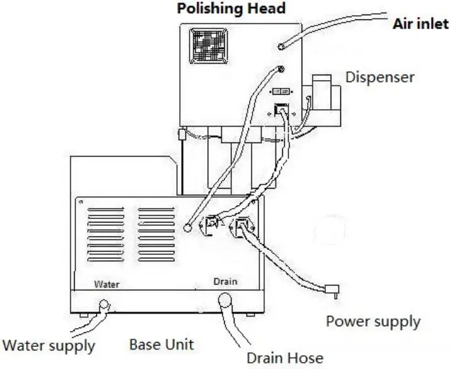
External air supply: It is recommended that the air supply be clean, filtered and lubricated to extend the life and performance of the systems.
Electrical connection: Connect electrical power cable and communications cable.
Heads Operation
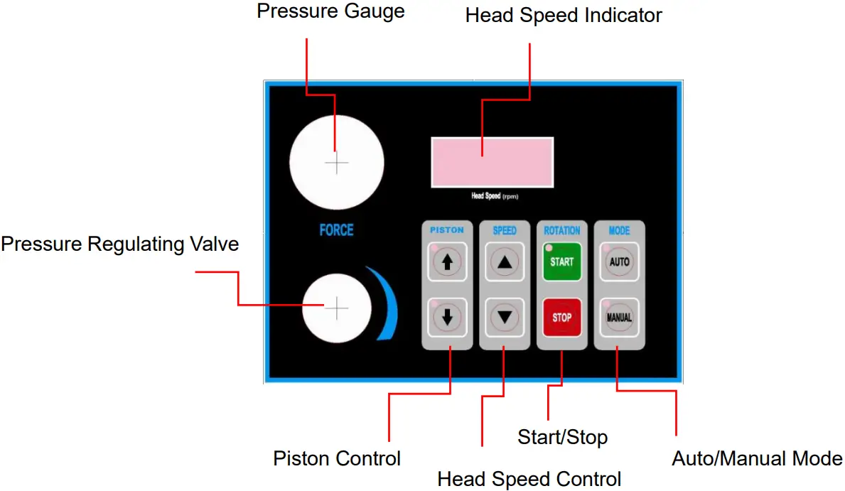
Start / stop buttons: Start or stops the head in the manual mode.
Auto/ manual: Manual mode operates the head independent of the polisher. Auto mode operates head in conjunction with the polisher.
Pistons control: UP/DOWN controls the pistons in the manual mode.
Head speed control: UP/DOWN arrows for increasing or decreasing the speed.
Head speed indicator: Displays the motor speed (0-200 rpm).
Pressure adjustment: Controls the pressure applied to the pistons.
Base Polisher Control Panel
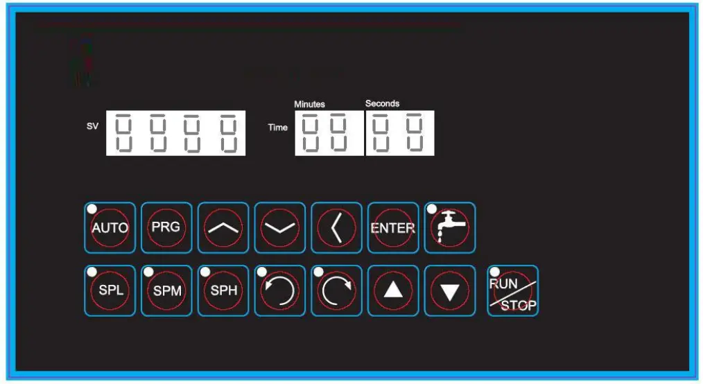
![]() Function key, press to display the function setting menu.
Function key, press to display the function setting menu.
![]() : Display the menu forward in turn, or increase the number.
: Display the menu forward in turn, or increase the number.
![]() : Display the menu in reverse order, or decrease the number.
: Display the menu in reverse order, or decrease the number.
![]() : When setting the value, switch the number of digits.
: When setting the value, switch the number of digits.
![]() : Enter button. When the function setting menu is displayed, press to display the corresponding parameter value, and press to save the set value after modifying the parameter
: Enter button. When the function setting menu is displayed, press to display the corresponding parameter value, and press to save the set value after modifying the parameter
![]() Control the water on and off.
Control the water on and off.
![]() : The operation mode of the working panel is auto mode, that is, there can be 8 sections of variable speed and the running time can be set.
: The operation mode of the working panel is auto mode, that is, there can be 8 sections of variable speed and the running time can be set.
![]() The operating speed of the working disk is the preset value of parameter SL.
The operating speed of the working disk is the preset value of parameter SL.![]() :The operating speed of the working disk is the preset value of parameter SN.
:The operating speed of the working disk is the preset value of parameter SN.![]() :The operating speed of the working disk is the preset value of parameter sh.
:The operating speed of the working disk is the preset value of parameter sh.![]() :Set the operating direction of the working wheel to counter clockwise
:Set the operating direction of the working wheel to counter clockwise![]() :Set the working wheel running direction to clockwise.
:Set the working wheel running direction to clockwise.![]() :Speed up.
:Speed up.![]() :Speed down.
:Speed down.![]() :Start / stop
:Start / stop
| Menu name | Description | Remarks |
| SP1 | Speed 1. Unit: RPM | SP1 ~ Sp8, T1 ~ T8 are called “8-stage speed” in this manual. When t is set to 0, the corresponding speed segment will skip and not run. To set the speed, press and to increase and decrease the speed value. Set the running direction by pressing and. |
| t1 | Running time for speed 1. Unit: Second | |
| SP2 | Speed 2 | |
| t2 | Running time of speed 2 | |
| SP3 | Speed 3 | |
| t3 | Running time of speed 3 | |
| SP4 | Speed 4 | |
| t4 | Running time of speed 4 | |
| SP5 | Speed 5 | |
| t5 | Running time of speed 5 | |
| SP6 | Speed 6 | |
| t6 | Running time of speed 6 | |
| SP7 | Speed 7 | |
| t7 | Running time of speed 7 | |
| SP8 | Speed 8 | |
| t8 | Running time of speed 8 | |
| Cn | Set the operation times of 8-stage speed. The operation from SP1 to Sp8 is one time. | When this parameter is set to 0, it will run until the stop key is pressed. |
| SL | Speed SPL. Low speed section | SPL, SPM and SPH are referred to as 3-stage speed in this manual. When the operating mode of the working disk is 3-stage speed, the speed in operation can be changed (increased or decreased) by pressing and |
| SLt | Timer for SPL. Unit: second. If set 0, it will keep running until press the stop button. | |
| Sn | Speed SPM. Medium speed section | |
| Snt | Timer for SPM. Unit: second. If set 0, it will keep running until press the stop button. | |
| SH | Speed SPH. High speed section | |
| SHt | Timer for SPH. Unit: second. If set 0, it will keep running until press the stop button. | |
| Sr | Set the transmission ratio between the motor and the working disk | This parameter can not be modified at will, otherwise the speed display will be inaccurate. Password is required to modify this parameter10: Display speed. 1: Display frequency. It is currently set to display only the speed. |
| dF | Restore all parameters to factory default values | This parameter can not be modified at will, otherwise the circuit board will be damaged. Password is required to modify this parameter |
| U | Set the input voltage (110 / 220 V). | |
| St | Set the protection temperature of frequency converter, when it exceeds the temperature, it will stop automatically | |
| Ct | Displays the current temperature of the inverter | |
| nS | The number of poles of the motor. | Password is required to modify this parameter |
| CD1 | Set the start / stop control mode | 0: through the panel. 1: It is controlled by inputting an external signal. Password is required to modify this parameter |
| CD2 | Set the display content of LED tube. | 10: Display speed. 1: Display frequency. It is currently set to display only the speed. |
Trouble Shooting
| Problem | Cause | Solution |
| No power or function | Unit is disconnected from main electrical power supply. Main power switch is off. Blown fuse | 1.Verify electrical source and connection. 2.Turn on main power switch. 3. Replace fuse |
| No air supply | Air regulator blocked | Clean air connections |
| Specimens not polished evenly across sample | Specimen not breaking down grinding paper uniformly. Relative velocity of base and head does not match. | Position specimen holder so that specimen tracks over the entire radius of the grinding paper. Match head and base speed |
Electrical Drawings
Drawings of the head.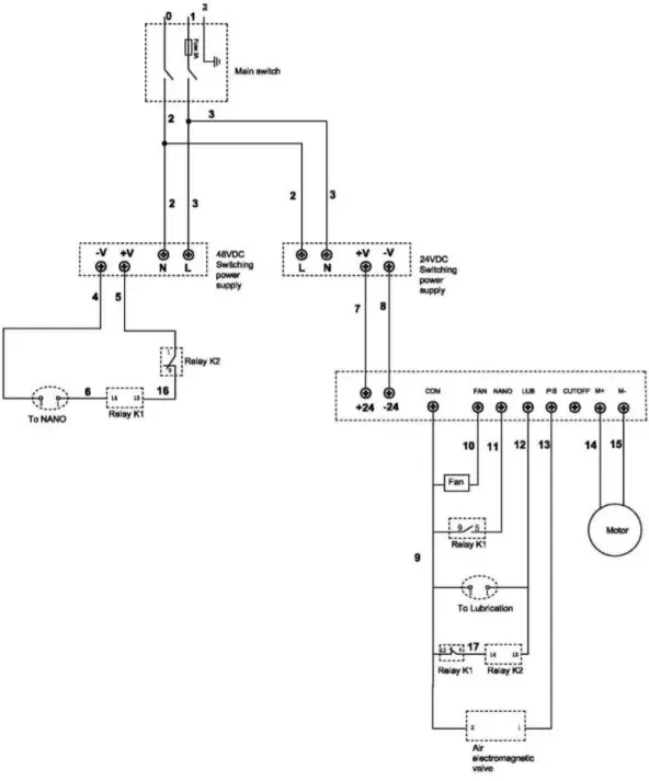
Drawings of the base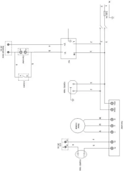
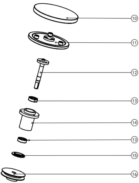
Schematics and Part list
| 10 | Working wheel | 1 |
| 11 | Support wheel | 1 |
| 12 | Spindle shaft | 1 |
| 13 | Bear ins | 2 |
| 14 | Bearing | 1 |
| 15 | Bearing end plate | 1 |
| 16 | Working wheel pulley | 1 |
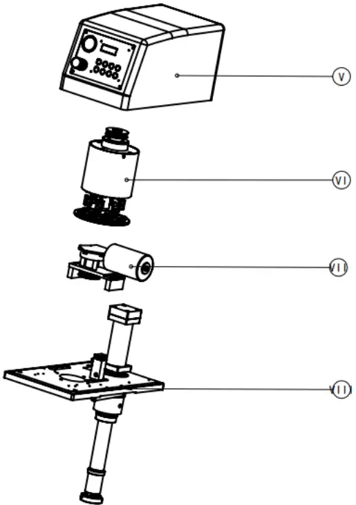
| I tems | Part Name | Quantity |
| v | Cover Assembly | 1 |
| V l | Grinding head | 1 |
| V l l | Motor Assembly | 1 |
| V l l l | Base Assembly | 1 |
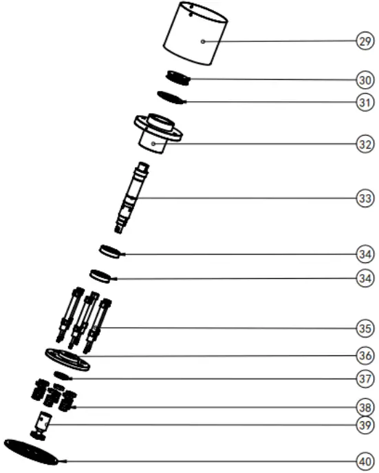
| I tems | Part Name | Quant it |
| 29 | Roller | 1 |
| 30 | Beit pulley | 1 |
| 31 | Bearing end plate | 1 |
| 32 | Flange | 1 |
| 33 | Spindle Shaft | 1 |
| 34 | Bearing | 2 |
| 35 | Ari Cylinder | 6 |
| 36 | Clamping plate | 1 |
| 37 | Nut | 1 |
| 38 | Cylinder parts | 6 |
| 39 | Adapting piece | 1 |
| 40 | Holder | 1 |
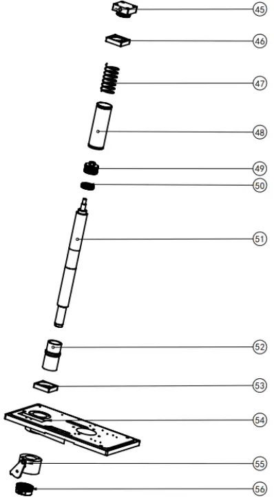
| I tems | Part Name | Quantiy |
| 45 | Cylinder block | 1 |
| 46 | Cylinder flange-2 | 1 |
| 47 | Spring | 1 |
| 48 | Cylinder Sleeve | 1 |
| 49 | Piston | 1 |
| 50 | Bearing | 1 |
| 51 | Piston rod | 1 |
| 52 | Cylinder | 1 |
| 53 | Cylinder flange-2 | 1 |
| 54 | Base | 1 |
| 55 | Fixing Sleeve | 1 |
| 56 | Locking ring | 1 |
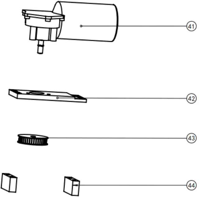
| I tems | Part Name | Quantiy |
| 41 | Motor | 1 |
| 42 | Motor bracket | 1 |
| 43 | Motor Pulley | 1 |
| 44 | Heel block | 2 |
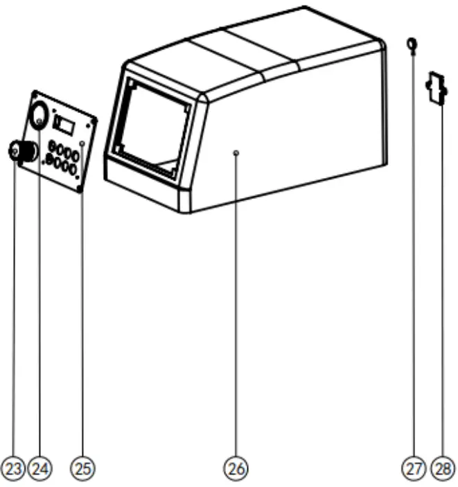
| I tems | Part Name | Quantiy |
| 23 | Air-vent Valve | 1 |
| 24 | Pressure gauge | 1 |
| 25 | Control Panel | 1 |
| 26 | Cover | 1 |
| 27 | Date interface | 1 |
| 28 | Switch | 1 |
Packing List
| NO | Name | Unit | Quality | Remark |
| 1 | Working wheels | Pc | 2 | |
| 2 | Abrasive Disc | Pc | 2 | |
| 3 | Polish cloth | Pc | 1 | |
| 4 | PU 8, water inlet | Pc | 1 | |
| 5 | 1-inch ID water outlet | Pc | 1 | |
| 6 | Power line | Pc | 1 | |
| 7 | Instruction Manual | 1 | ||
| 8 | Packing list | Pc | 1 |