BLUE JAY CBM3000 Circuit Breaker Manager
CBM3000 Circuit Breaker Manager
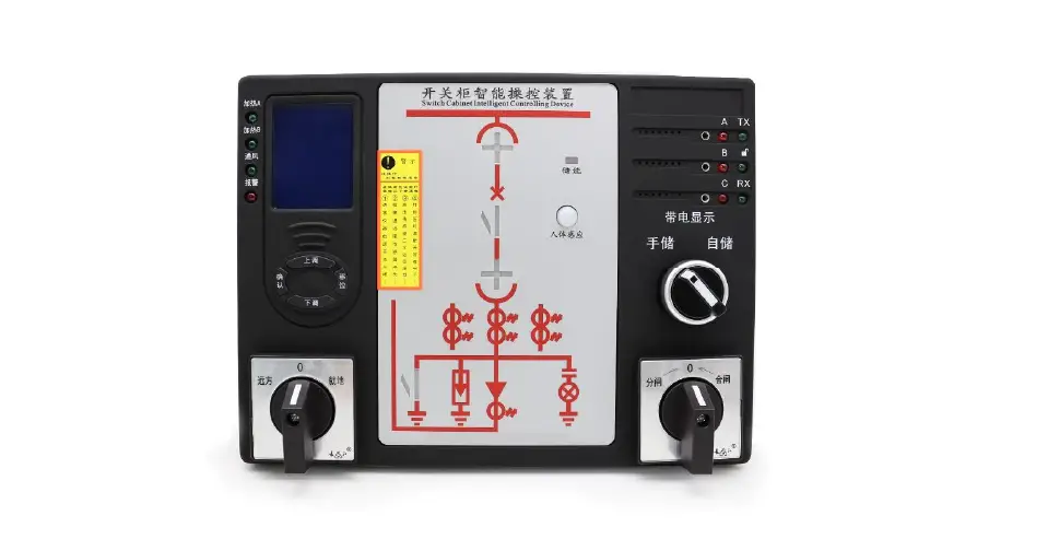
The CBM3000 Circuit Breaker Manager is a new generation product designed for 3~35KV indoor switchgear. It is suitable for switchgear cabinet, handcart cabinet, fixed cabinet, RMU, and other types of switchgears. The product provides real-time display for temperature and humidity, automatic heating dehumidification control, circuit breaker status indication, spring storage and grounding switch indicator, and also shows the circuit diagram and the simulation sub-switch LED to indicate. All products use industrial-grade electronic components with rigorous design and manufacturing processes to ensure high reliability, long life, and strong anti-interference capability. The product meets standards DL/T538-2006 [High voltage live display device technical conditions].
Technical Parameters
- Voltage level: 3~35KV
- Temperature range: -40°C~+85°C
- Humidity range: 0%~100%RH
- Power supply: AC220V±10% 50Hz
- Power Consumption: ≤10W
- Communication interface: RS485 or Ethernet
- Storage capacity: 2GB SD card
Installation and Start-Up
- Connect the power supply in strict accordance with the marked voltage level, and the wiring must be strictly in accordance with the markings on the terminals on the back.
- During installation, tighten the terminals and fix the equipment in a place that is strong, fire-resistant, and not easy to vibrate. Install the equipment vertically, with a height of 1.8m.
- During the withstand voltage test, disconnect the high voltage live display sensor plug, disconnect the temperature and humidity sensor plug, and the wireless receiving head.
- All digital contacts must be passive access.
- Wiring according to the actual wiring mark, subject to change without prior notice.
- The company is not responsible for improper use or malfunctions not caused by this product.
Note: Please read this user manual carefully and save it for future reference.
Read me
When you use CBM3000, be sure to carefully read this user manual, and be able to fully understand the implications, the correct guidance of operations in accordance with user manual, which will help you make better use CBM3000, and help to solve the various problems at the scene.
- The power supply must be connected in strict accordance with the marked voltage level, and the wiring must be strictly in accordance with the markings on the terminals on the back.
- During installation, the terminals should be tightened, and the equipment should be fixed in a place that is strong, fire-resistant, and not easy to vibrate. The effect is best when the equipment is looking up, so it should be installed vertically, and the height should be 1.8M.
- During the withstand voltage test, it is necessary to disconnect the high voltage live display sensor plug, disconnect the temperature and humidity sensor plug and the wireless receiving head.
- All digital contacts must be passive access.
- Wiring according to the actual wiring mark, subject to change without prior notice.
- The company is not responsible for improper use or malfunctions not caused by this product.
- Please read this user manual carefully
- Please save this document
SUMMARIZE
CBM3000 Circuit Breaker Manager is a new generation product mainly design and development for 3 ~ 35KV indoor switchgear, it is suitable for switchgear cabinet, handcart cabinet, fixed cabinet, RMU and other types switchgears. The product provides real-time display for temperature and humidity; automatic heating dehumidification control; circuit breaker status indication; spring storage and grounding switch indicator; also show the circuit diagram and the simulation sub-switch LED to indicate.
Products all use industrial-grade electronic components, Rigorous design and manufacturing process make high reliability, long life, and strong anti-interference capability. Meet standards DL/T538-2006 [High voltage live display device technical conditions].
APPLICATIONS
- Automatically cut off the power
- Monitor the operating status of electrical equipment
- Monitor electrical energy consumption in power systems
- Power equipment in substations and power plants
- Ensuring the Safety and Reliability of Power Systems
- Reduce energy consumption and enhance equipment safety
- Automated remote control and monitoring
FEATURES
- Automatically cut off the power
- With door lock indicator (NC/NO)
- Optional high voltage indicator
- Optional RS485 communication
- Switchgear inside temperature & humidity display (LED or LCD)
- With electronic thermostat can automatic control fan /heater
- With primary side analog diagram to show switchgear inner wiring
- Integrated led indicator to show switch position, breaker position, earth switch position, VCB spring energy state
TECHNICAL PARAMETERS
| Basic parameters | |
| Auxiliary Power | 85~265Vac/dc |
| Power consumption | 15VA |
| Display screen | LCD with 4 button operation key |
| Communication | RS-485, MODBUS-RTU |
| Environment temperature | -10 ~ +60°C |
| Environment humidity | RH 20% ~ 95% (No condensation) |
| Altitude | <3000m |
| Withstand voltage | AC2000V/1min |
| Dielectric strength | 100Mohm |
| Electromagnetic compatibility | Comply with IEC255-22 |
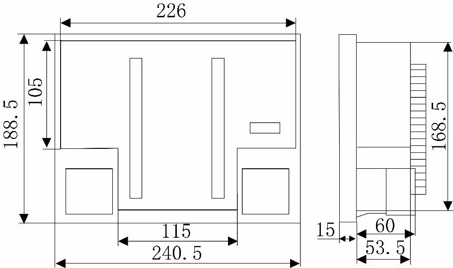
| Dimensions | 250x190x68mm (WxHxD) |
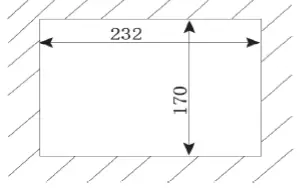
| Install hole open | 226x165mm |
| Temperature protection relay | |
| Temperature set range | -20C ~80C |
| Resolution | 0.1C |
| Humidity set range | 0% ~ 100% |
| Resolution | 0.1%RH |
| Integrate power metering | |
| Network | 1P2W, 3P3W, 3P4W |
| Rated voltage | AC100V, 220V, 380V depends on VT |
| Burden | <0.1VA (Per phase) |
| Rated current | AC1A, 5A depends on CT |
| Burden | <0.4VA (Per phase) |
| Accuracy level | full scale 0.5%, RMS |
| Frequency range | 40~65Hz, accuracy: ±0.02Hz |
| Power | KW and Kvar, accuracy: 0.5% |
| Energy | Kwh 0.5S class, Kvarh 2.0 class |
| Other protection functions | |
| High voltage indicator sensitive | [Rated voltage] x 0.15~0.65 |
| Door lock relay act voltage | >[Rated voltage] x 0.65 |
INSTALLATION AND START-UP
The manual you hold in your hands contains information and warnings that the user should respect in order to guarantee a proper operation of all the instrument functions and keep its safety conditions. The instrument must not be powered and used until its definitive assembly on the cabinet’s door.
Whether the instrument is not used as manufacturer’s specifications, the protection of the instrument can be damaged.
When any protection failure is suspected to exist (for example, it presents external visible damages), the instrument must be immediately powered off. In this case contact a qualified service representative.
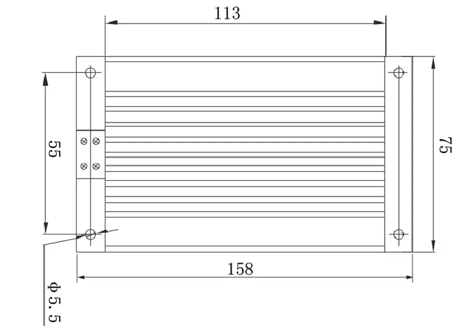
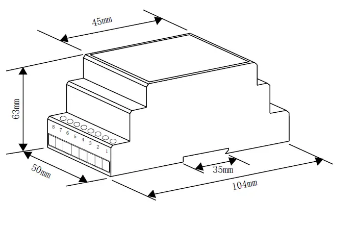
Dimension:
Installation hole: unit mm
Physical Dimensions: unit mm
Sensor mounting
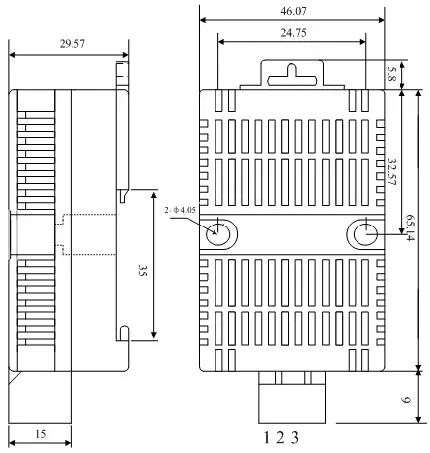
- Using 35mm rail mounting or screw.
- Fixed installation (pitch 37mm diameter 4mm).
- Using the interface plug-ins to connect temperature and humidity sensors and instruments
Heater size
Basic functions introduction
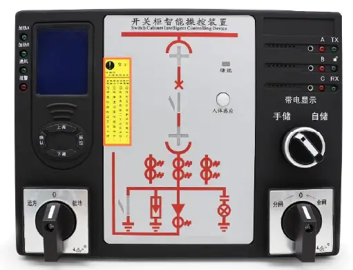
Front panel introduction
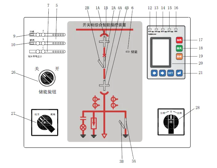
| No. | Description |
| 1A,4A | working position indication |
| 1B,4B | test position indication |
| 2A | Circuit breaker (VCB) closed indication |
| 2B | Circuit breaker (VCB) opened indication |
| 3A | Grounding switch closed indication |
| 3B | Grounding switch opened indication |
| 5 | Voice alarm speaker |
| 6 | Spring storage indicator |
| 7 | High voltage indicator |
| 9 | Door locked indicator |
| 10 | Door unlocked indicator |
| 12 | Heater_1 working condition indicator |
| 13 | Heater_2 working condition indicator |
| 14 | Fan_1 working condition indicator |
| 15 | Fan_2 working condition indicator |
| 16 | Cabinet lighting ON indicator |
| 17 | Forced Heating |
| 18 | Forced cooling |
| 19 | Button “open cabinet lighting/ Move the cursor right” |
| 20 | LCD screen area |
| 21 | Operation button |
| 26 | Switch for spring storage Off/On |
| 27 | Switch for Remote/local selection |
| 28 | Switch for Closing/opening |
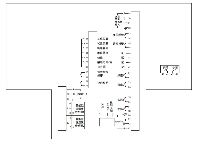
Rear panel introduction
| No. | Description | No. | Description | |||
| 21 | VCB working |
DI terminal from VCB | 33 | Switchgear safety locker |
Passive NO node | |
| 22 | VCB test | 34 | ||||
| 23 | VCB opened | 44 | Phase lose | |||
| 24 | VCB closed | 45 | ||||
| 25 | Spring storage | 51 | Fan 1 controlled by Probe 1 | |||
| 26 | Ground switch Opened/Closed | 52 | ||||
| 27 | COM port for VCB | 53 | Fan 2 controlled by Probe 2 | |||
| 56 | Sensor, disconnect detect loop | Passive DO | 54 | |||
| 57 | 35 | Heater 1 controlled by Probe 1 | ||||
| 15 | Light loop | Passive DO | 36 | |||
| 16 | 37 | Heater 2 controlled by Probe 2 | ||||
| 58 | RS485 port A |
COMM | 38 | |||
| 59 | RS485 port B | 61 | A |
Wireless probe terminal | ||
| 60 | RS485 GND | 62 | B | |||
| 81 | Temperature Humidity Probe 1 |
Input | 63 | GND | ||
| 82 | Temperature Humidity Probe 2 | 64 | + | |||
| 29 | Phase A high voltage sensor | Input | 1 | Power supply | ||
| 30 | Phase B high voltage sensor | 2 | AC/DC110~220V | |||
| 31 | Phase C high voltage sensor | GND | ||||
| 32 | Ground for high voltage sensor | 40~43 Spring storage/released | ||||
OPERATION MODE
Button description
 On and off function of the heating output relay.
 On and off function of the exhaust output relay.
 Control the lighting function on or off.
 Set the menu to scroll upwards during programming or switch forward; Long press is the self-check function
 Set the menu to scroll upwards during programming or switch next;
 Enter the programming menu, exit the menu level by level.
 Confirm and save the entered information or displayed settings.
 On and off function of the exhaust output relay.
 Control the lighting function on or off.
 Confirm and save the entered information or displayed settings.
4.2.-Parameter setting
In the measurement state, press the ” 
 ” keys, the screen will display the following data in sequence:
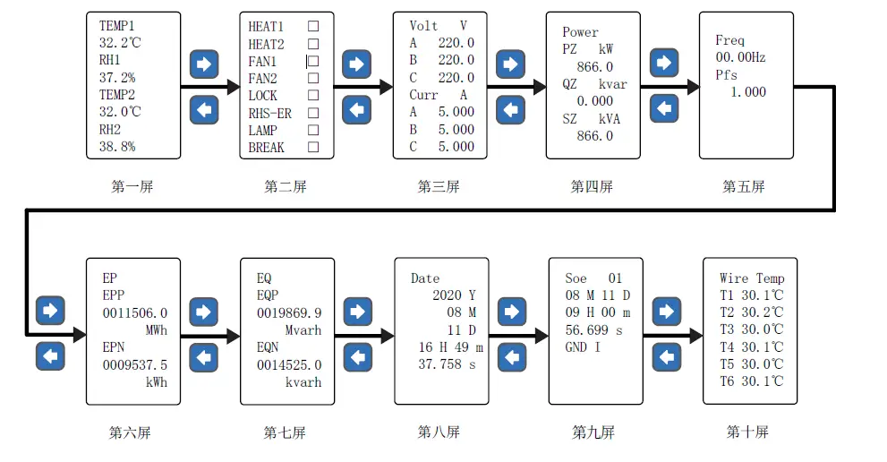
| Screen No. | Definition |
| Screen-1 | Temperature and humidity values and exhaust air heating control status |
| Screen-2 | The working status of the relay |
| Screen-3 | The effective value of three-phase voltage and current |
| Screen-4 | Active power, reactive power and apparent power |
| Screen-5 | Power factor and frequency |
| Screen-6 | Active energy consumed and generated |
| Screen-7 | Reactive energy consumed and generated |
| Screen-8 | RTC |
| Screen-9 | Event logging |
| Screen-10 | Multi-channel wireless temperature measurement value |
Press ”  ” key to enter the menu programming state, enter the correct password (factory password is 0001,) to confirm the specific parameter settings. It needs to be saved after setting up and exit. The programming menu structure and description are shown in the following table:
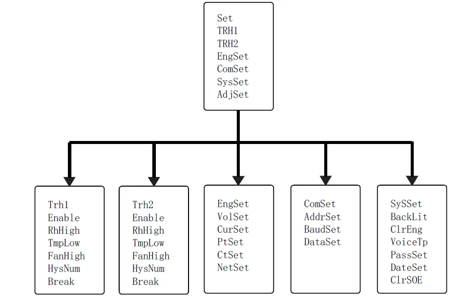
Menu layer
| Level-1 | Level-2 | Level-3 | Description |
| Temperature and humidity 1 and 2 | Status | ON | ” ON ” and ” OFF ” are optional |
| Dehumidifying | Start>XX%; Stop< XX% | Start 5%RH~99%RH Stop 0%RH~94%RH | |
| Heating | Start<XXXX°C; Stop >XXXX°C | Start -40°C ~+35°C Stop -35°C ~+40°C | |
| Cooling | Start >XXXX°C; Stop <XXXX°C | Start -35°C ~+125°C Stop -40°C ~+120°C | |
| Hysteresis | XX | left and right arrows to select, and Enter key to confirm. | |
| Delay | XX sec | ||
| Load disconnection | ON | “ON” and “OFF” are optional | |
| Electrical test settings | Voltage range | 100V | 100V or 380V, Default 100V |
| Current range | 5A | 5A or 1A, Default 1A | |
| Voltage ratio | XXXX | Voltage magnification ratio | |
| CT ratio | XXXX | Current magnification ratio | |
| Wiring mode | 4P3L | 3P4L\3P3L3CT\3P3L2CT | |
| Comm | Device address | XXX; | 001~255 |
| Baud rate | XXXX | 2400,4800,9600,19200 | |
| Data Format | n.8.1 | n.8.1 \0.8.1\e.8.1\ n.8.2 | |
| SYS | Backlight control | XXXX Min | left and right arrows to select, and Enter key to confirm. |
| Reset counter | ON | ” ON ” for reset to zero | |
| Voice | ON | ” ON ” and ” OFF ” are optional | |
| Reset password | XXXX | Enter the 4-digit new password |
Notes: Part of the content is modifiable or optional.
FUNCTIONS INTRODUCTION
Status indication function
| Functions | Definition |
| VCB indicate | When the handcart is in the working position (working position contact is closed), the handcart indicator red (1A, 4A) light is on; |
| When the handcart is in the test position (the contact in the test position is closed), the green (1B, 4B) lights of the driving indicator are on; | |
| When the handcart is in the working position or between the test position and the working position, close the grounding knife forcibly, and the indicator lights (1A, 1B, 4A, 4B) of the handcart will continue to flash; | |
| When the handcart is not in the cabinet (the contacts in the working and test positions are not closed and the contacts of the circuit breaker are disconnected), the red and green (1A, 4A, 1B, 4B) lights of the handcart indicator are not on; | |
| Circuit breaker status indicate | When the circuit breaker is closed (the contact of the circuit breaker is closed), the indicator light (2A) of the circuit breaker is on; |
| When the circuit breaker is open (circuit breaker sub-contact is closed), the circuit breaker indicator green (2B) light is on; | |
| When the circuit breaker is not in the cabinet (both closed and open contacts of the circuit breaker are not closed), the red and green (2A, 2B) indicators of the circuit breaker are off; | |
| Ground switch indicate | When the grounding switch is closed (the opening/closing contact of the grounding switch is closed), the grounding switch indicator red (3A) light is on; |
| When the grounding switch is not closed (the opening/closing contact of the grounding switch is not closed), the green (3B) light of the grounding switch is on | |
| Spring status indicate | When the contact is closed, the energy storage indicator red light (6) is on; |
Intelligent voice warning function
Warning 1:
When the circuit breaker is closed and the handcart is between the test position and the working position (the contacts of the test position and the working position are both disconnected), the 1A, 4A, 1B, 4B, 2B indicator lights flash, and the 2A indicator light is always on. Lights up and there is a voice prompt “Please turn off the circuit breaker”
Warning 2:
When the handcart is in the working position or between the test position and the working position, close the grounding knife forcibly, the 1A, 4A, 1B, 4B, 3B indicator lights will flash, the 3A indicator light will always be on and there will be a voice prompt “Please open the grounding switch ”
Warning 3:
When both the grounding knife and the circuit breaker are closed, when the trolley is accidentally pushed to switch from the test position to the working position, the 2B and 3B indicator lights will flash at the same time, accompanied by language prompts “Please switch off the circuit breaker” and “Please switch off the grounding switch”
Warning 4:
When the circuit is electrified and the human body senses a signal, there will be a voice prompt of “This circuit is electrified”
High voltage indicate and lock function
| Functions | Definition |
| High voltage live display | When the three phases A, B, and C are charged (voltage ≥ 15% of the rated voltage), the corresponding three- phase indicators (7) of A, B, and C will start to glow; |
| High voltage live lock | When any one of the three phases A, B, and C is electrified (voltage ≥ 65% of the rated voltage), the high- voltage lock indicator red light (9) is on, the high-voltage unlock indicator green light (10) is off, and the corresponding high-voltage lock contact output pops open; When the three phases are not charged, the green light (10) of the high-voltage unlocking indicator is on, the red light (9) of the high-voltage locking indicator is off, and the output of the corresponding high-voltage locking contact is closed; |
| High voltage phase loss alarm | When any one or two of the three phases A, B, and C are charged (voltage ≥ 65% of the rated voltage), the phase loss alarm contact output is closed; When all three phases are not charged or all three phases are charged, the phase loss alarm contact The output is turned on. |
Note: A, B, C three-phase matching sensor, its output short-circuit current must reach 220uA ± 10%.
Operation function
| Functions | Definition |
| Switch off/on storage | |
| Opening/closing operation | |
| Remote/local conversion | |
| Test | In the measurement state, long press ” |
| Cabinet lighting | In the measurement state, press the button |
Working mode
| Functions | Definition |
| Measurement | In the measurement state, the area 20 displays the current channel, temperature, humidity value, electrical parameter value, switch status, etc., and can choose to cycle display. For the specific interface, please refer to the “Instructions for Use” below. |
| Control | When the temperature or humidity of the environment meets the pre-set working conditions, the heater or fan is started, and the corresponding indicator light is on. When the load fails and does not work according to the conditions, the corresponding load disconnection relay is closed, and the Appears on the display. |
| Control test | Under normal working conditions, press  button to force heat; button to force heat;press |
Setting mode
Enter/exit system setting mode
Enter the system: Under normal condition, press button to enter the system setting mode. Press ![]() the left and right keys to enter the password. refer to the following “Instructions” for each setting interface.
the left and right keys to enter the password. refer to the following “Instructions” for each setting interface.
Note: The default password is 0001.
Wireless temperature measurement function
Wireless Temperature Receiver:
Each device can be equipped with 1 wireless temperature receiver and 9 (according to customer needs can be expanded to 12) wireless temperature collector, each 3 serial number connected wireless temperature collector is a group.
Dimension: unit(mm)
Installation: 35mm Din rail
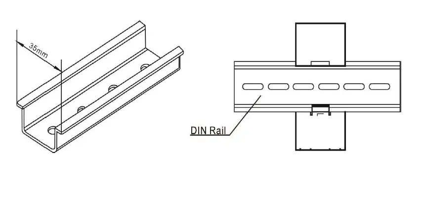
Wireless temperature collector:
The specific installation method of the wireless temperature collector is shown in the figure below. Each collector has a temperature-sensing point, and the temperature measured by the collector is the temperature of the temperature-sensing point.
If the collector is placed in the air, the measured temperature is ambient temperature. In order to accurately measure the temperature of the surface of the object, it should be ensured that the temperature-sensing surface of the collector is in close contact with the surface of the object to be measured.

Watch strap wireless temperature collector
Each control device can be equipped with 1 wireless temperature receiver and 9 (can be expanded to 12 according to customer needs) wireless temperature collectors, and every 3 serial numbers connected wireless temperature collectors form a group.
Note: When installing, follow the position marked on the label on the wireless temperature collector. If the installation location is not corresponding, the temperature displayed on the control device from T1 to T12 is not the temperature of the actual location.
The supporting wireless receiving box (rail-mounted installation) must be installed in the handcart room of the circuit breaker, and connected to the control device through a 4-core connecting line (preferably shielded cable). The corresponding connection relationship is as follows:
Wiring method of wireless temperature receiver:
| 8 | 7 | 6 | 5 | 4 | 3 | 2 | 1 |
| +5V | ┻ | 485B | 485A | power light | N | L |
The connection method between the wireless temperature receiver and the control terminal
| Wireless routing adapter terminal number | Temperature measurement terminal number | |
| 8 | +5V | 64 |
| 7 | ┻ | 63 |
| 6 | 485B | 62 |
| 5 | 485A | 61 |
| 4 | power light | |
When a wireless temperature sensor detects that the surface temperature of the target point exceeds the upper alarm limit, the red alarm light on the front of the device flashes, the corresponding serial number of the wireless temperature measurement display interface changes to “!” Flashes, and the information is saved in the event record; When the surface temperature of the target point exceeds the upper limit of the alarm, the alarm output relay draws in; when the surface temperature of the target point drops to the exit alarm temperature point (Th-5°C), the device automatically exits the alarm state of this aspect.
Technical Parameters
| Resolution | 0.1°C |
| Measurement accuracy | < ± 1°C |
| Measurement range | -40°C-150°C |
| Measurement interval | 0.5s |
| Sending interval | 1-60s (Adjustable) |
| Battery life | >= 5 years |
| Working temperature | -20°C ~80°C |
| Working environment humidity | ≤95%RH |
| Collection point and receiver distance | ≤80 meters (open viewing distance) |
| Receiver size | 60*45*26mm |
| Positioning hole diameter | 3mm |
| Positioning hole center distance | 69.6mm |
COMMUNICATION INTERFACE
MODBUS © protocol
CBM3000 can choose RS485 communication interface and support standard Modbus-RTU communication protocol.
Modbus RTU Frame Format:
| Address | 1-247 |
| Baud | 2400bps,4800bps, 9600bps,192000 bps |
| Data format | N. 8. 1 0. 8. 1 E. 8. 1 N. 8. 2 |
Note:
For detailed Modbus-RTU communication protocol description, please visit http://www.modbus.org, can refer to document Modbus_Application_Protocol_V1_1a.pdf.
Register Map
| Addr. | Data | Description | Byte |
| Secondary side parameters (integer data) | |||
| 0x00 | Ua | Phase-line voltage data, unit 0.1V | 1 |
| 0x01 | Ub | 1 | |
| 0x02 | Uc | 1 | |
| 0x03 | Uab | Phase-phase voltage data, unit 0.1V | 1 |
| 0x04 | Ubc | 1 | |
| 0x05 | Uca | 1 | |
| 0x06 | Ia | Current data, unit 0.001A | 1 |
| 0x07 | Ib | 1 | |
| 0x08 | Ic | 1 | |
| 0x09 | Pa | Split phase active power, unit 0.1W | 1 |
| 0x0a | Pb | 1 | |
| 0x0b | Pc | 1 | |
| 0x0c | P∑ | Total active power, unit 1W | 1 |
| 0x0d | Qa | Split phase reactive power, unit 0.1var | 1 |
| 0x0e | Qb | 1 | |
| 0x0f | Qc | 1 | |
| 0x10 | Q∑ | Total reactive power, unit 1var | 1 |
| Reserved | 1 | ||
| 0x14 | S∑ | Total apparent power, unit 1VA | 1 |
| Reserved | 1 | ||
| 0x18 | cosQ | Power factor 0~1.000 | 1 |
| 0x19 | FR | Frequency 0.01Hz | 1 |
| 0x1a | Ep+ | Positive active energy, unit Wh | 2 |
| 0x1c | Ep- | Reverse active energy (generated) | 2 |
| 0x1e | Eq+ | Inductive reactive energy, unit Varh | 2 |
| 0x20 | Eq- | Capacitive reactive energy, unit Varh | 2 |
| Reserved | 1 | ||
| 0x28 | T1 | Temperature sensor 1,Unit 0.1°C | 1 |
| 0x29 | RH1 | Humidity sensor 1,Unit 0.1%RH | 1 |
| 0x2A | T2 | Temperature sensor 2,Unit 0.1°C | 1 |
| 0x2B | RH2 | Humidity sensor 2,Unit 0.1%RH | 1 |
| Reserved | 1 | ||
| 0x44 | DI | Input signal status: 0 for opened, 1 for closed |
1 |
| 0x45 | DO | Output signal status: 0 for opened, 1 for closed [Bit 0] Heater_1 [Bit 1] Heater_2 [Bit 2] Fan_1 [Bit 3] Fan_2 [Bit 4] Door locker [Bit 5] Phase loose [Bit 6] Light lamp [Bit 7] Load disconnect |
1 |
| Primary side parameters (floating point data) | |||
| 0x100 | Ua | Phase-line voltage data, unit V | 2 |
| 0x102 | Ub | 2 | |
| 0x104 | Uc | 2 | |
| 0x106 | Uab | Phase-phase voltage data, unit V | 2 |
| 0x108 | Ubc | 2 | |
| 0x10a | Uca | 2 | |
| 0x10c | Ia | Current data, unit A | 2 |
| 0x10e | Ib | 2 | |
| 0x110 | Ic | 2 | |
| 0x112 | Pa | Split phase and total active power, unit kW | 2 |
| 0x114 | Pb | 2 | |
| 0x116 | Pc | 2 | |
| 0x118 | P∑ | 2 | |
| 0x11a | Qa | Split phase and total reactive power, unit kvar | 2 |
| 0x11c | Qb | 2 | |
| 0x11e | Qc | 2 | |
| 0x120 | Q∑ | 2 | |
| Reserved | 2 | ||
| 0x128 | S∑ | Total apparent power KVA | 2 |
| Reserved | 2 | ||
| 0x130 | COSQ | Power factor 0~1.000 | 2 |
| 0x132 | FR | Frequency 0.01Hz | 2 |
| 0x134 | Ep+ | Positive active energy, Unit kWh | 2 |
| 0x136 | Ep- | Reverse active energy (generated) | 2 |
| 0x138 | Eq+ | Inductive reactive energy, unit kVarh | 2 |
| 0x13a | Eq- | Capacitive reactive energy, unit kVarh | 2 |
| Wireless temperature measurement (integer data) | |||
| 0x300 | WX_T1 | Wireless probe-1(0.1°C) | 1 |
| 0x301 | WX_T2 | Wireless probe-2 | 1 |
| 0x302 | WX_T3 | Wireless probe-3 | 1 |
| 0x303 | WX_T4 | Wireless probe-4 | 1 |
| 0x304 | WX_T5 | Wireless probe-5 | 1 |
| 0x305 | WX_T6 | Wireless probe-6 | 1 |
| 0x306 | WX_T7 | Wireless probe-7 | 1 |
| 0x307 | WX_T8 | Wireless probe-8 | 1 |
| 0x308 | WX_T9 | Wireless probe-9 | 1 |
| 0x309 | WX_T10 | Wireless probe-10 | 1 |
| 0x30A | WX_T11 | Wireless probe-11 | 1 |
| 0x30B | WX_T12 | Wireless probe-12 | 1 |
| 0x30C | WX_T13 | Wireless probe-13 | 1 |
| 0x30D | WX_T14 | Wireless probe-14 | 1 |
| 0x30E | WX_T15 | Wireless probe-15 | 1 |
TECHNICAL SERVICE
For any inquiry about the instrument performance or whether any failure happens, contact to Blue Jay’s technical service.
- If there is any not understand in the description when user installation instructions, please contact technical directly.
- Company technology will answer any questions at any time.
- Issues arising from the use of the product within one working day to respond.
- These products is 1-year warranty, free of charge maintenance for life.
Blue Jay – After-sales service
1802,Building 2,No.88,Jianxin East Road, Chongqing,400020,China
Tel – + 0086 023 67628702
E-mail: [email protected]
Tel: +0086-023-67628702
www.cqbluejay.com
Add: 1802,Building 2,No.88,Jianxin East Road,Chongqing,400020,China
Email :[email protected]


