STANLEY BR87 Heavy Duty Breakers
Parts Illustration
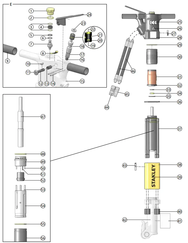
| BR87 Parts Illustration – Detail E | ||
| ITEM | P/N | DESCRIPTION |
| 1 | 06687 | Valve Cap |
| 2 | 04052 | O-ring* |
| 3 | 01772 | O-ring |
| 4 | 06684 | Sintered Filter |
| 5 | 22768 | Seal Spacer |
| 6 | 06688 | Retaining Ring |
| 7 | 04051 | Charge Valve |
| 8 | 10180 | Caution: Nitrogen Gas Under Pressure Decal |
| 9 | 02494 | Handle Grip |
| 10 | 11432 | Woodruff Key – Model BR8713201FS, BR8717201 |
| 11 | 01003 | Valve Button – Model BR8713201FS |
| 12 | 11431 | Lock Pin – Model BR8713201FS, BR8717201 |
| 13 | 11430 | Spring – Model BR8713201FS, BR8717201 |
| 14 | 22891 | Roll Pin |
| 15 | 04049 | Handle |
| 11435 | Handle – Model BR8713201FS, BR8717201 | |
| 16 | 05465 | Orifice Plug |
| 17 | 04058 | Spring |
| 18 | 04077 | Valve Spool |
| 19 | 01362 | O-ring* |
| 20 | 04057 | Bushing |
| 21 | 00293 | O-ring* |
| 22 | 04056 | Rod Wiper* |
| 23 | 04055 | Washer |
| 24 | 04053 | Trigger |
| 11434 | Trigger – Model BR8713201FS, BR8717201 | |
| 25 | 28322 | CE Decal |
| 26 | 11207 | Circuit Type “D” Decal |
| 27 | 58601 | Sound Power Decal |
| 28 | 28409 | Composite Safety Decal |
| 29 | 04054 | O-ring* |
| 30 | 04060 | Accumulator Cylinder |
| 31 | 04059 | Accumulator Diaphragm |
| 32 | 05309 | Accumulator Chamber |
| 33 | 05301 | Backup Washer |
| 34 | 05307 | Rod Seal* |
| 35 | 04064 | Seal Retainer Washer |
| 36 | 24666 | Elastomeric Spacer |
| 37 | 04071 | Side Rod |
| 38 | 05265 | Flow Sleeve Housing |
| 39 | 74832 | STANLEY Logo Decal |
| 40 | 04075 | Side Rod Nut |
| 41 | 11208 | Hex Shank Length Decal – Model BR8717201 |
| 42 | Depends on Model | Breaker Foot – See Detail F & G |
| 43 | 74673 | Tool Name Tag |
| 74666 | Tool Name Tag – Model BR87120D | |
| 44 | 03972 | Female Coupler |
| 45 | 03973 | Male Coupler |
| 46 | 01652 | Hose |
| 47 | 16812 | Piston |
| 48 | 04054 | O-ring* |
| 49 | 04066 | Automatic Valve Body |
| 50 | 04571 | Push Pin |
| 51 | 07890 | Roll Pin |
| 52 | 04065 | Automatic Valve |
| 53 | 04067 | Push Pin |
| 54 | 04069 | Flow Sleeve |
| 55 | 04054 | O-ring* |
| 56 | 04068 | Flow Sleeve Tube |
| 57 | 05485 | Seal Kit (Not Shown) – * In Seal Kit |
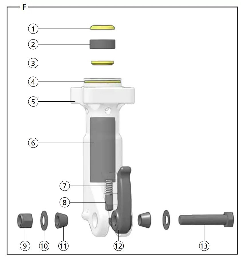
| Breaker Foot Assembly – Detail F | |||||
MODEL | |||||
| ITEM | DESCRIPTION | QTY | BR87120, BR87120D, BR87120J | BR87130, BR8713201FS | BR87320 |
| 1 | Cup Seal | 1 | 34127* | ||
| 2 | Seal Insert | 1 | 05466 (Must purchase entire foot assembly) | 05467 (Must purchase entire foot assembly) | 08855 (Must purchase entire foot assembly) |
| 3 | Rod Wiper | 1 | 04074* | ||
| 4 | O-ring | 1 | 04073* | ||
| 5 | Breaker Foot | 1 | 05466 (Must purchase entire foot assembly) | 05467 (Must purchase entire foot assembly) | 08855 (Must purchase entire foot assembly) |
| 6 | Hex Bushing | 1 | 05466 (Must purchase entire foot assembly) | 05467 (Must purchase entire foot assembly) | 08855 (Must purchase entire foot assembly) |
| 7 | Spring | 1 | 01744 | ||
| 8 | Detent | 1 | 08411 | ||
| 9 | Nylock Nut | 1 | 04984 | ||
| 10 | Washer | 2 | 04985 | ||
| 11 | Taper Sleeve | 2 | 01269 | ||
| 12 | Latch | 1 | 01837 | ||
| 13 | Foot Latch Bolt | 1 | 04983 | ||
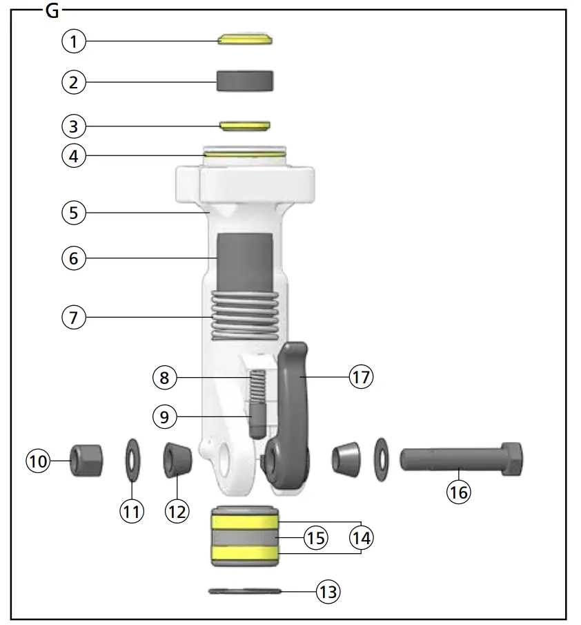
| Breaker Foot Assembly – Detail G | |||||
MODEL | |||||
| ITEM | DESCRIPTION | QTY | BR8713015E, BR87130E (07486) | BR87120E (07523 | BR8717201 (11638) |
| 1 | Cup Seal | 1 | 34127* | ||
| 2 | Seal Insert | 1 | 07486 (Must purchase entire foot assembly) | 07523 (Must purchase entire foot assembly) | 11638 (Must purchase entire foot assembly) |
| 3 | Rod Wiper | 1 | 04074* | ||
| 4 | O-ring | 1 | 04073* | ||
| 5 | Breaker Foot | 1 | 07486 (Must purchase entire foot assembly) | 07523 (Must purchase entire foot assembly) | 11638 (Must purchase entire foot assembly) |
| 6 | Hex Bushing | 1 | 07486 (Must purchase entire foot assembly) | 07523 (Must purchase entire foot assembly) | 11638 (Must purchase entire foot assembly) |
| 7 | Spring | 1 | 07514 | ||
| 8 | Spring | 1 | 01744 | ||
| 9 | Detent | 1 | 08411 | ||
| 10 | Nylock Nut | 1 | 04984 | ||
| 11 | Washer | 2 | 04985 | ||
| 12 | Taper Sleeve | 2 | 01269 | ||
| 13 | Retaining Ring | 1 | 07522 | ||
| 14 | Wear Ring | 2 | 07516 | ||
| 15 | Collar Support | 1 | 07520 | 07519 | 12013 |
| 16 | Foot Latch Bolt | 1 | 04983 | ||
| 17 | Latch | 1 | 01837 | ||
Safety Precautions
 | The Safety Alert Symbol alerts you to potential personal injury hazards. Obey all safety messages that follow to avoid possible injury or death. |
 | Indicates an imminently hazardous situation which will result in death or serious injury. |
 | Indicates a potentially hazardous situation which could result in death or serious injury |
 | Indicates a potentially hazardous situation which could result in property damage. |
Always observe safety symbols. They are included for your safety and for the protection of the tool.
 | WARNING: Read all safety warnings and instructions. Failure to follow the warnings and instructions may result in tool damage and/or serious injury. WARNING: To reduce the risk of injury, read the instruction manual. |
General
- Do not discard safety instructions. Give to the operator.
- This tool will provide dependable service if operated in accordance with the instructions given in this manual. Read and understand this manual and any stickers and tags attached to the tool and hoses before operation. Failure to do so could result in personal injury or equipment damage.
- Inspect the tool before each use and ensure all decals are legible. Contact STANLEY if replacements are needed.
- Establish a training program for all operators to ensure safe operation. Do not operate the tool unless thoroughly trained or under the supervision of an instructor. Keep out of the reach of children.
- Operators and maintenance personnel shall be able to physically handle the bulk, weight and power of the tool.
- Avoid unsuitable postures as these positions do not allow for counteracting of normal or unexpected movement of the tool, such as a sudden break of the tool bit. Change postures during extended tasks to help avoid discomfort or fatigue.
- Never use the tool unless the inserted tool is retained with a proper retainer.
- Do not operate a damaged, improperly adjusted, modified or incompletely assembled tool.
- Use and maintain the tool as stated in this manual. Misuse of the tool can cause serious injury. Do not modify the tool in any way.
- Do not operate the tool in explosive atmospheres, such as in the presence of flammable liquids, gases or dust. Power tools create sparks which may ignite the dust or fumes.
- Provide adequate ventilation in closed areas when operating a gas or diesel hydraulic power source.
- Do not inspect, carry, clean, change accessories or perform maintenance on the tool while the power source is connected. Accidental engagement of the tool can cause serious injury.
- Ensure work piece is securely fixed. Be aware that failure of the work piece or accessories may generate high velocity projectiles.
- Never use the tool bit as a hand struck tool.
- Stay alert, watch what you are doing and use common sense when operating a hydraulic tool. Do not operate this tool if you are tired or under the influence of drugs or alcohol. A moment of inattention while operating hydraulic tools may result in serious injury.
- During operation, do not contact mechanisms, accessories or hardware as they can become very hot or sharp; use your Personal Protection Equipment (PPE).
- Supervising personnel should develop additional precautions relating to the specific work area and local safety regulations.
- Never operate the tool if you are unsure about the presence of underground utilities, such as electrical cables, gas pipes, etc. These can cause a hazard if damaged with the tool.
- The tool is not insulated against coming into contact with electric power. Use hose certified as non-conductive.
- Do not overreach. Maintain proper footing and balance at all times when using the tool.
- Slips, trips and falls are major causes of workplace injury. Be observant of hoses or oil surfaces lying about the work area, as they can be a tripping hazard.
- Operators must start in a work area without bystanders and must assess the risks to bystanders.
- Keep work area clean and well lit. Cluttered or dark areas invite accidents.
- Operators must be familiar with all prohibited work areas such as excessive slopes and dangerous terrain conditions.
- Only use clean hydraulic fluid, filling equipment and lubricants that have been recommended by STANLEY.
- Ensure tools are working properly and safely by performing preventative maintenance (PM) procedures.
- Repair and service of this tool must only be performed by an authorized
and certified dealer. - Do not force the tool to do the work of a larger tool. Use the correct tool for your application.
- Use only hoses and hose couplings that are rated for a minimum working pressure of 2500 PSI (172 BAR).
- In spite of the application of relevant safety regulations and the implementation of safety devices, certain residual risks cannot be avoided. These risks are: repetitive strain injury due to incorrect posture and risk of pinching fingers when changing tool bit.
Dust and Fumes
- WARNING: Some dust created by power sanding, sawing, grinding, drilling, and other construction activities contains chemicals known to the State of California to cause cancer, birth defects or other reproductive harm. Some examples of these chemicals are:
- Lead from lead-based paints,
- crystalline silica from bricks and cement and other masonry products, and
- arsenic and chromium from chemically-treated lumber.
Your risk from these exposures varies, depending on how often you do this type of work. To reduce your exposure to these chemicals: work in a well ventilated area, and work with approved safety equipment, such as those dust masks that are specially designed to filter out microscopic particles. Protect yourself and those around you. Research and understand the materials you are grinding. Follow correct safety procedures and comply with all applicable national, state or provisional health and safety regulations relating to them, including, if appropriate arranging for the safe disposal of the materials by a qualified person.
- When dust or fumes are created, control them at the point of emission. Direct tool exhaust to minimize disturbance of dust.
- Operate and maintain the tool as recommended in this manual to minimize dust.
- Use respiratory protection in accordance with employers instruction or as required by occupational health and safety regulations.
- Avoid prolonged contact with dust. Allowing dust to get into your mouth, eyes or lay on the skin may promote absorption of harmful chemicals.
PPE
- Always wear safety equipment such as impact resistant goggles, ear protection, head protection, breathing protection and safety shoes at all times when operating the tool.
- Hands may be exposed to hazards, impacts, cuts, abrasions and heat. Wear gloves.
- Wear a hardhat if performing overhead work.
- Use PPE that conforms to standards ANSI Z87.1 (Eye and Face Protection), ANSI Z89.1 (Head Protection), ANSI Z41.1 (Foot Protection) and ANSI S12.6 (S3.19) (Hearing Protection).
- Do not wear loose fitting clothing or jewelry when operating the tool.
 M003 Wear Ear ProtectionM004 Wear Eye ProtectionM016 Wear a Mask
 M003 Wear Ear Protection
 M004 Wear Eye Protection
 M016 Wear a Mask
Sound
- Exposure to high noise levels can cause permanent, disabling hearing loss and other problems, such as tinnitus (ringing, buzzing, whistling or humming in the ears). Use hearing protection in accordance with employer’s instructions and as required by occupational health and safety regulations.
- Use and maintain as recommended in the manual to prevent an unnecessary increase in noise levels.
Vibration
- When using a non-rotary percussive tool to perform work related activities, the operator can experience discomfort in the hands, arms, shoulders, neck or other parts of the body.
- If you experience numbness, tingling, pain or whitening of the skin in your fingers or hands, stop using the tool. Tell your employer and consult a physician.
- Wear warm clothing when working in cold conditions and keep your hands warm and dry.
- Exposure to vibration can cause disabling damage to the nerves and blood supply of the hands and arms.
- Use and maintain as recommended in the manual to prevent an unnecessary increase in vibration.
- Check for vibration level before each service. If you feel a higher than normal vibration, contact your STANLEY dealer for repair.
Hydraulic
- Warning: Hydraulic fluid under pressure could cause skin injection injury. Do not check for leaks with your hands. If you are injured by hydraulic fluid, get medical attention immediately.
- Do not let hydraulic oil get on the skin. Hydraulic oil is hot. Wear Personal Protection Equipment (PPE) at all times.
- If exposed to hydraulic fluid, wash hands immediately.
- Do not exceed the maximum relief valve setting stated on the tool.
- Inspect and clean couplers before use, daily. Replace damaged couplers immediately.
- Hydraulic circuit control valve must be OFF before coupling or uncoupling tools. Failure to do so may damage the couplers and cause overheating of the hydraulic system.
- Ensure the couplers are properly connected and are tight.
- Do not operate the tool at fluid temperatures above 140°F (60°C). Higher temperatures can cause operator discomfort and damage to the tool.
- Do not exceed the rated flow and pressure as stated on the tool. Rapid failure of the internal seals may result.
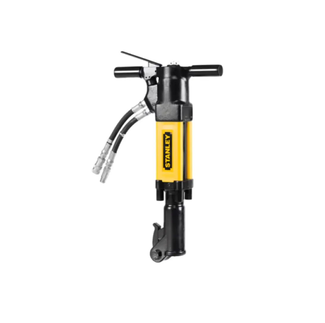
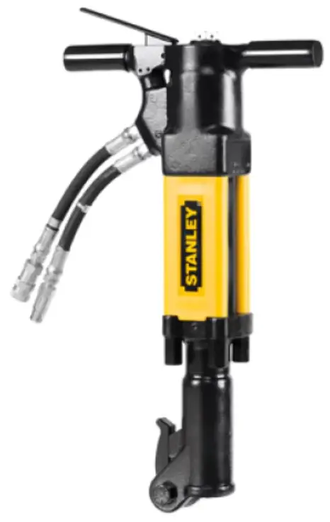
What is a BR87 Hydraulic Breaker?
BR87 is a hydraulic breaker for use in the 90 lbs. weight class. Its highly productive in utility construction, street maintenance, repair of water and gas mains, and general contracting jobs. BR87 requires an external hydraulic power source capable of supplying 7-9 GPM.
| Specifications | |
| Pressure | 1500-2500 PSI (103-172 BAR) |
| Flow | 7-9 GPM (26-34 LPM) |
| Max. Pressure | 2000 PSI (138 BAR) |
| Max. Relief Pressure | 2150 PSI (148 BAR) |
| Recommended Back Pressure | 250 PSI (17 BAR) or less – Can be used with higher back pressures with reduced seal life. |
| Couplers | 3/8 inch Male Pipe Hose Ends |
| Port Size | -8 SAE O-ring |
| Tool Weight | 83 Lbs (38 Kg) |
| Tool Length | 29 inches |
| Width (at handles) | 16 inches |
| Max. Hydraulic Oil Temp. | 140°F (60°C) |
| HTMA/EHTMA Category | Type II, Category D |
| Sound & Vibration Declaration | |
| Measured A-Weighted sound power level | 104.4 dBA |
| Uncertainty | 2.2 dBA |
| Measured A-Weighted Sound Pressure | 107 dBA |
| Values determined according to noise test code given in ISO 15744, using the basic standard ISO3744. Test conducted by independent notified body to comply with 2000/14/EC:2005. | |
| Measured Vibration Emission Value: 3-Axis (Trigger Handle) | 23.5 m/sec² |
| Measured Vibration Emission Value: 3-Axis (Non- Trigger Handle) | 21.7 m/sec² |
| Uncertainty | 6.6 m/sec² |
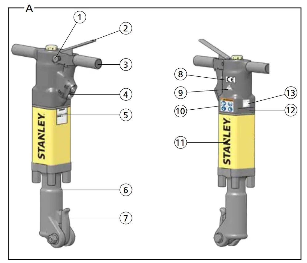
Parts of a BR87 – Detail A
| 1 | Trigger Lock |
| 2 | Trigger |
| 3 | Handle |
| 4 | Hydraulic Supply Ports |
| 5 | Tool Name Tag |
| 6 | Breaker Foot |
| 7 | Breaker Foot Latch |
| 8 | CE Decal |
| 9 | Circuit Type “D” Decal |
| 10 | Composite Safety Decal |
| 11 | STANLEY Logo Decal |
| 12 | Serial Number & Year of Manufacture |
| 13 | Sound Power Decal |
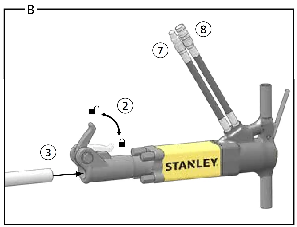
Tool Setup – Detail B
![]() Do not install or change tool accessories while the hydraulic power source is connected. Accidental engagement of the tool can cause serious injury. Disconnect the hydraulic power source before installing or changing accessories.
Do not install or change tool accessories while the hydraulic power source is connected. Accidental engagement of the tool can cause serious injury. Disconnect the hydraulic power source before installing or changing accessories.
- Disconnect the tool from the hydraulic power source.
Install the Breaker Bit The tool bit can get extremely hot during operation. Always wear gloves when installing bits. Hot bits can cause burns.
 - Unlock the breaker foot latch.
- Insert the tool bit and lock the latch. Never use BR87 unless the tool bit is locked in the retainer.
Note: Never use a blunt tool bit as they cause more vibration
Connect to a Hydraulic Power Source - Using a calibrated flow and pressure gauge, check the output of the hydraulic power source. Ensure it matches the flow and pressure in “Specifications” on page 9. Hydraulic fluid must be 50°F or above. Preheat if necessary.
- Ensure that the hydraulic power source is equipped with a relief valve
set to open at the maximum relief pressure. See “Specifications” on page 9. - Wipe hose couplers with a clean, lint free cloth.
- Connect the return hose to the tool port marked “Out”.
- Connect the pressure hose to the tool port marked “In”.
- Ensure couplers are undamaged, properly connected and are tight.
- Power up the hydraulic power source.
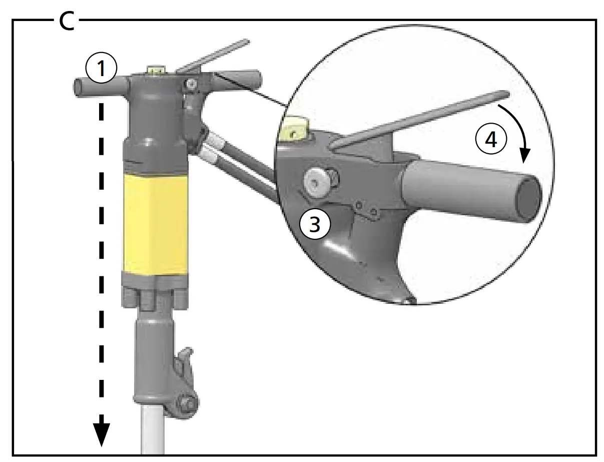
Tool Operation – Detail C
![]() Always hold tool with both hands to maximize control. Apply proper down pressure and maintain proper footing at all times.
Always hold tool with both hands to maximize control. Apply proper down pressure and maintain proper footing at all times.
- Wrap your hands around the handles. Stand in back of the tool, using your leg against the snap-on filler for stability.
Note: Hold the tool correctly and be ready to counteract normal or sudden movements. Have both hands available. - Place the breaker bit on the material to be broken, at a 90° angle. Apply down pressure.
- Push the trigger lock button in towards the handle (CE models only).
- Slowly squeeze the trigger to start breaking. Squeeze harder for fast speed operation.
- When starting, break until the tool bit breaks through, then reposition the bit. Do not use the tool bit as a lever to move material.
Note: Never cool a hot tool bit in water. Tools can become brittle and fail. - Continue breaking around the original hole, in 2 inch sized bites.
- Release trigger to stop the tool.
Note: If you encounter a breakdown or the tool stops for any reason, release the trigger and power down the hydraulic power source.
Tool Maintenance
![]() Do not perform maintenance on the tool while the hydraulic power source is connected. Accidental engagement of the tool can cause serious injury. Disconnect the hydraulic power source before servicing
Do not perform maintenance on the tool while the hydraulic power source is connected. Accidental engagement of the tool can cause serious injury. Disconnect the hydraulic power source before servicing
Daily Maintenance
- Remove hydraulic power from the tool and check all hydraulic connections and hoses for damage. Replace damaged parts before operating the tool.
- Inspect the tool bit latch and associated parts. Replace when they have become worn, cracked or distorted.
- Inspect tool to ensure all stickers are legible. Contact STANLEY if replacements are needed.
- Check the flow and pressure of the hydraulic power source using a calibrated flow meter. Proper flow and pressure maintain proper tool speed. If tool speed increases or decreases, stop using the tool and ensure proper flow and pressure.
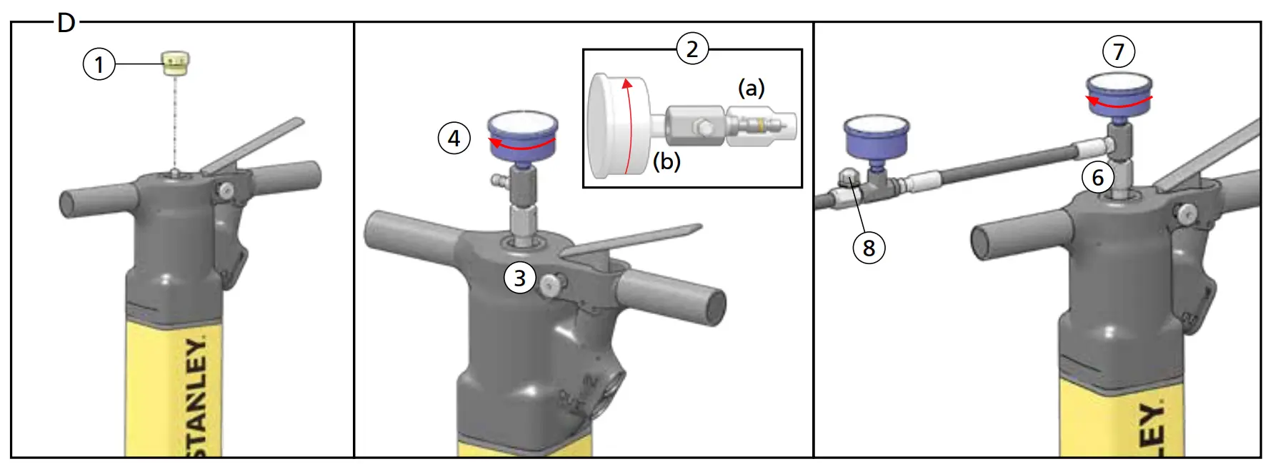
Check/Charge the Accumulator – Detail D
Check accumulator charge every 6 months or if poor performance develops.
Required Tools:
- STANLEY Accumulator Charge Kit (P/N 31254)
- Nitrogen Bottle
Check
- Remove the charging plug from the breaker handle.
- (a) Hold the chuck end of the tester and (b) twist the gauge counterclockwise. This will retract the valve stem.
- Screw the tester onto the breaker charging port.
- Twist the tester gauge clockwise and read the pressure indicated on the gauge. Charge should be 700-900 PSI (48-62 BAR).
Charge - Retract the tester valve stem.
- Connect the charging assembly hose to the tester.
- Twist the tester gauge clockwise to advance the valve stem.
- Slowly open the snub valve and charge to 800 PSI (55 BAR).
- Close the snub valve, retract the tester valve stem and remove the tester from the breaker charging port. Replace the charging plug.
Tool Storage & Transport
Storage
Plug open hydraulic ports. Clean the tool and store in a clean, dry space that is safe from damage.
Transport
Secure the tool to the transport vehicle. Lift only as high as necessary to load. NEVER lift or transport over people. Ensure tool is secured and will not move during transport. An unsecured tool could cause personal injury or damage to the tool.
Tool Disposal
Hydraulic Oil
Hydraulic oil can contaminate the air, ground and water if not properly recycled. Recycle hydraulic oil in accordance with all State, Federal and local laws, at your local oil recycling facility.
Hydraulic Hoses
Hang hydraulic hoses to drain. Collect the oil for recycling. Contact your local municipal recycling authorities for an approved hydraulic hose recycling site.
Tool Body
Drain hydraulic oil from the tool, making sure to collect the oil for recycling. Discharge the accumulator, disassemble the tool and dispose of all non-metal parts. Recycle the metal components. Contact your local municipal recycling authorities for recycling instructions.
Accessories
| Description | Part Number |
| 1 1/8 Inch Hex x 6 inch Shank | |
| Moil Point, 14 Inch Long, UC | 02333 |
| Chisel Point, 14 Inch Long, UC | 03990 |
| Description | Part Number |
| 3 Inch Chisel, 14 Inch Long, UC | 02334 |
| Clay Spade, 5 1/2 Inch Blade | 02331 |
| Asphalt Wedge, 12 Inch | 08106 |
| Asphalt Cutter, 5 Inch Wide | 02332 |
| Ground Rod Driver, 1 Inch Rod | 04176 |
| 1 1/4 Inch Hex x 6 Inch Shank | |
| Moil Point, 14 Inch Long, UC | 02336 |
| 3 Inch Chisel, 14 Inch Long, UC | 02337 |
| Clay Spade, 5 1/2 Inch Blade | 09262 |
| Asphalt Cutter, 5 Inch Wide | 02335 |
| Ground Rod Driver, 1 Inch Rod | 04367 |
| Heavy Duty Chisel, 1 Inch | 02338 |
| Heavy Duty Moil Point, 18 Inch | 04404 |
| Clay Spade, 8 Inch | 04405 |
| Asphalt Wedge | 08119 |
Troubleshooting
| Problem | Possible Cause | Solution |
| Tool does not run or runs improperly. | The hydraulic power source is not running or not running properly. | Ensure the power source delivers proper flow and pressure. See “Specifications” on page 9. Proper flow and pressure maintain proper tool speed. Check regularly. |
| Couplers or hoses are blocked. | Turn off and disconnect the tool from hydraulic power source. Ensure no blockage exists. | |
| Low accumulator charge. | Check and recharge accumulator. See “Check/Charge the Accumulator – Detail D” on page 10. | |
| Hydraulic fluid too hot. | Provide a cooler to maintain temperature. See “Specifications” on page 9. | |
| High back pressure. | Check the hydraulic system for excessive back pressure. | |
| Mechanical failure of piston or automatic valve. | Contact your STANLEY dealer for service. | |
| Fluid leakage on tool bit. | Lower piston seal failure. | Contact your STANLEY dealer for service. |
| Fluid leakage around the tool trigger. | Valve spool failure. | Contact your STANLEY dealer for service. |
Customer Support
STANLEY Infrastructure
6430 SE Lake Road, Portland, Oregon 97222 USA
(503) 659-5660 / Fax (503) 652-1780
www.stanleyinfrastructure.com