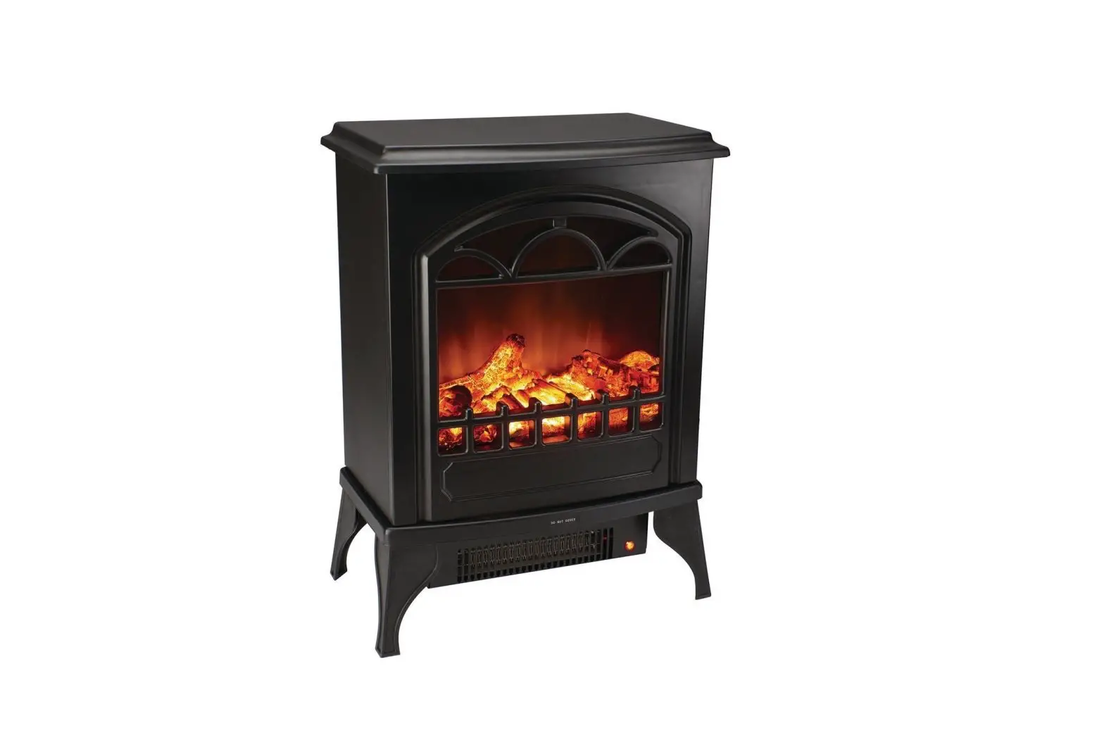
HARBOR FREIGHT 61796 1500W Wood Stove Style Electric Heater Owner’s Manual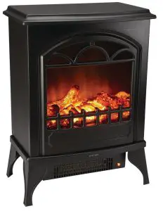
Owner’s Manual & Safety Instructions
Save This Manual Keep this manual for the safety warnings and precautions, assembly, operating, inspection, maintenance and cleaning procedures. Write the product’s serial number in the back of the manual near the assembly diagram (or month and year of purchase if product has no number). Keep this manual and the receipt in a safe and dry place for future reference.
WARNING SYMBOLS AND DEFINITIONS
WARNING SYMBOLS AND DEFINITIONS | |
 | This is the safety alert symbol. It is used to alert you to potential personal injury hazards. Obey all safety messages that follow this symbol to avoid possible injury or death. |
 | Indicates a hazardous situation which, if not avoided, will result in death or serious injury. |
 | Indicates a hazardous situation which, if not avoided, could result in death or serious injury. |
 | Indicates a hazardous situation which, if not avoided, could result in minor or moderate injury. |
  | Addresses practices not related to personal injury. |
IMPORTANT SAFETY INFORMATION
![]() When using electrical appliances, basic precautions should always be followed to reduce the risk of fire, electric shock, and injury to persons, including the following:
When using electrical appliances, basic precautions should always be followed to reduce the risk of fire, electric shock, and injury to persons, including the following:
- Read all instructions before using this heater.
- This heater is hot when in use. To avoid burns, do not let bare skin touch hot surfaces. Keep combustible materials, such as furniture, pillows, bedding, papers, clothes, and curtains at least 3 feet (0.9 m) from the front of the heater and keep them away from the sides and rear.
- Extreme caution is necessary when any heater is used by or near children or invalids and whenever the heater is left operating and unattended.
- Always unplug heater when not in use.
- Do not operate any heater with a damaged cord or plug or after the heater malfunctions, has been dropped or damaged in any manner. Return heater to authorized service facility for examination, electrical or mechanical adjustment, or repair.
- Do not use outdoors.
- This heater is not intended for use in bathrooms, laundry areas and similar indoor locations.
Never locate heater where it may fall into a bathtub or other water container. - Do not run cord under carpeting. Do not cover cord with throw rugs, runners, or similar coverings. Arrange cord away from traffic area and where it will not be tripped over.
- To disconnect heater, turn controls to off, then remove plug from outlet.
- Do not insert or allow foreign objects to enter any ventilation or exhaust opening as this may cause an electric shock or fire, or damage the heater.
- To prevent a possible fire, do not block air intakes or exhaust in any manner. Do not use on soft surfaces, like a bed, where openings may become blocked.
- A heater has hot and arcing or sparking parts inside. Do not use it in areas where gasoline, paint, or flammable liquids are used or stored.
- Use this heater only as described in this manual. Any other use not recommended by the manufacturer may cause fire, electric shock, or injury to persons.
- Avoid the use of an extension cord because the extension cord may overheat and cause a risk of fire. However, if you have to use an extension cord, the cord shall be 16 AWG minimum size and rated not less than 1,500 watts.
- The output of this heater may vary and its temperature may become intense enough to burn exposed skin. Use of this heater is not recommended for persons with reduced sensitivity to heat or an inability to react to avoid burns.
- Heater service must be performed only by an authorized service representative. Service or maintenance performed by unqualified personnel could result in a risk of fire or injury.
- Do not abuse the Power Cord. Never use the Power Cord to carry this heater or pull the Plug from an outlet. Keep the Power Cord away from heat, oil, or sharp edges. Replace damaged Power Cords immediately. Damaged Power Cords increase the risk of electric shock.
- Disconnect the Power Cord Plug from the power source and allow the heater to thoroughly cool before making any adjustments, changing accessories, or storing this heater. Such preventive safety measures reduce the risk of burns.
- When servicing this heater, use only identical replacement parts. Follow instructions in the “Inspection, Maintenance, and Cleaning” section of this manual. Use of unauthorized parts or failure to follow maintenance instructions may create a risk of electric shock or injury.
- People with pacemakers should consult their physician(s) before use. Electromagnetic fields in close proximity to heart pacemaker could cause pacemaker interference or pacemaker failure.
- The warnings, precautions, and instructions discussed in this instruction manual cannot cover all possible conditions and situations that may occur. It must be understood by the operator that common sense and caution are factors which cannot be built into this product, but must be supplied by the operator.
![]() SAVE THESE INSTRUCTIONS.
SAVE THESE INSTRUCTIONS.
Grounding
![]()
 TO PREVENT ELECTRIC SHOCK AND DEATH FROM INCORRECT GROUNDING WIRE CONNECTION:
Check with a qualified electrician if you are in doubt as to whether the outlet is properly grounded.
Do not modify the power cord plug provided with the tool. Never remove the grounding prong from the plug. Do not use the tool if the power cord or plug is damaged. If damaged, have it repaired by a service facility before use. If the plug will not fit the outlet, have a proper outlet installed by a qualified electrician.
Grounded Tools: Tools with Three Prong Plugs
- 3-Prong Plug and Outlet


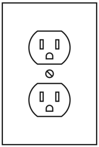
- Tools marked with “Grounding Required” have a three wire cord and three prong grounding plug. The plug must be connected to a properly grounded outlet. If the tool should electrically malfunction or break down, grounding provides a low resistance path to carry electricity away from the user, reducing the risk of electric shock. (See 3-Prong Plug and Outlet.)
- The grounding prong in the plug is connected through the green wire inside the cord to the grounding system in the tool. The green wire in the cord must be the only wire connected to the tool’s grounding system and must never be attached to an electrically “live” terminal. (See 3-Prong Plug and Outlet.)
- The tool must be plugged into an appropriate outlet, properly installed and grounded in accordance with all codes and ordinances. The plug and outlet should look like those in the preceding illustration. (See 3-Prong Plug and Outlet.)
Extension Cords
- Grounded tools require a three wire extension cord.
Double Insulated tools can use either a two or three wire extension cord. - As the distance from the supply outlet increases, you must use a heavier gauge extension cord. Using extension cords with inadequately sized wire causes a serious drop in voltage, resulting in loss of power and possible tool damage. (See Table A.)
- The smaller the gauge number of the wire, the greater the capacity of the cord. For example, a 14 gauge cord can carry a higher current than a 16 gauge cord. (See Table A.)
- When using more than one extension cord to make up the total length, make sure each cord contains at least the minimum wire size required. (See Table A.)
- If you are using one extension cord for more than one tool, add the nameplate amperes and use the sum to determine the required minimum cord size. (See Table A.)
- If you are using an extension cord outdoors, make sure it is marked with the suffix “W-A” (“W” in Canada) to indicate it is acceptable for outdoor use.
- Make sure the extension cord is properly wired and in good electrical condition. Always replace a damaged extension cord or have it repaired by a qualified electrician before using it.
- Protect the extension cords from sharp objects, excessive heat, and damp or wet areas.
TABLE A: RECOMMENDED MINIMUM WIRE GAUGE FOR EXTENSION CORDS* (120/240 VOLT)
NAMEPLATE
AMPERES
(at full load)
EXTENSION CORD LENGTH
25´
50´ 75´ 100´ 150´
0 – 2.0
18
18 18 18 16
2.1 – 3.4
18
18 18 16 14
3.5 – 5.0
18 18 16 14 12
5.1 – 7.0
18
16 14 12 12
7.1 – 12.0
18
14 12 10 –
12.1 – 16.0
14 12 10 – –
16.1 – 20.0
12
10 – – –
* Based on limiting the line voltage drop to five volts at 150% of the rated amperes.
Symbology
| Double Insulated |
| Volts Alternating Current |
| Amperes |
n0 xxxx/min. | No Load Revolutions per Minute (RPM) |

 | Read the manual before set-up and/or use. |
 | WARNING marking concerning Risk of Fire. Do not cover ventilation ducts. Keep flammable objects away. |
 | WARNING marking concerning Risk of Electric Shock. Properly connect power cord to appropriate outlet. |
Assembly
![]() Read the ENTIRE IMPORTANT SAFETY INFORMATION section at the beginning of this manual including all text under subheadings therein before set up or use of this product.
Read the ENTIRE IMPORTANT SAFETY INFORMATION section at the beginning of this manual including all text under subheadings therein before set up or use of this product.
![]()
TO PREVENT SERIOUS INJURY FROM ACCIDENTAL OPERATION:
Turn the Switches of the heater off, unplug the heater from its electrical outlet, and allow the heater to cool completely before performing any procedure in this section.
Note: For additional information regarding the parts listed in the following pages, refer to Parts List and Assembly Diagram on pages 6 and 7.
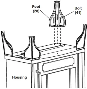
- Install one Foot (28) on each corner of the housing using 3 Bolts (41) as shown in Figure A.

- Make sure all Feet are installed securely before use.
Do not use with any Feet missing, bent, crooked or loose.
Operating Instructions
Read the ENTIRE IMPORTANT SAFETY INFORMATION section at the beginning of this manual including all text under subheadings therein before set up or use of this product.![]()
TO PREVENT SERIOUS INJURY FROM ACCIDENTAL OPERATION:
Turn the Switches of the heater off, unplug the heater from its electrical outlet, and allow the heater to cool completely before performing any procedure in this section.
- Place Heater on dry, hard, stable floor away from combustible materials. DO NOT USE ON CARPET.
Note: If the Heater is tilted at a 45° or greater angle, the tip-over switch will issue a warning sound and the heater will shut off. - Supervise children closely when near heater.
- Keep pets away from heater.
Controls
Note: Controls are located on the side of the Heater housing.
- Figure B: Control Pane
ON OFF
OFF
LOW HEAT
HIGHT HEAT
- On/Off: Switch to I position to turn the unit on and enable the flame effect.
- Low Heat: Switch to I position to turn the heater and fan on low.
Note: Low Heat must be on to use High Heat. - High Heat: Switch to I position to set the heather and fan on high.
Note: If heater reaches an unsafe temperature (212°F/100°C) the Temperature Limiting Control will automatically turn the Heater off. - 4. To reset:
- a. Unplug the power cord from the outlet.
- b. Turn the ON/OFF switch to OFF.
- c. Wait 5 minutes.
- d. Inspect the fireplace to make sure no vents are blocked, or clogged with dust or lint. If they are, use a vacuum to clean the vent areas.
- e. With the POWER switch in the OFF position, plug the power cord back into the outlet.
General Operating Instructions
- .To prevent accidental operation, turn the Switches off, then plug the heater into a grounded 120VAC electrical outlet.
- Adjust the controls as desired.
- After use, to prevent accidents, turn the Switches off, and unplug the power cord.
WARNING! Do not leave the heater unattended while switched on.
WARNING! TO PREVENT SERIOUS INJURY:
Allow Heater to cool completely before cleaning or storage. Once cool, clean, then store the heater indoors out of children’s reach.
Inspection and Maintenance
![]() Procedures not specifically explained in this manual must be performed only by a qualified technician.
Procedures not specifically explained in this manual must be performed only by a qualified technician.
![]()
TO PREVENT SERIOUS INJURY FROM ACCIDENTAL OPERATION: Turn the Switches.
of the heater off, unplug the heater from its electrical outlet, and allow the heater to cool completely before performing any procedures in this section.
to cool completely before performing any procedures in this section.
TO PREVENT SERIOUS INJURY AND FIRE FROM HEATER FAILURE:
Do not use damaged equipment. If abnormal noise or vibration occurs, have the problem corrected before further use.
Cleaning and Maintenance
- BEFORE EACH USE, inspect the general condition of the heater. Check for loose hardware, misalignment or binding of moving parts, cracked or broken parts, damaged electrical wiring, and any other condition that may affect its safe operation.
- For the metal parts of the Heater:
- a. Buff using a soft cloth, slightly dampened with a citrus oil-based product.
- b. DO NOT use brass polish or household cleaners as these will damage the metal.
- For the glass parts of the Heater:
- a. Use glass cleaner and dry thoroughly with a paper towel or lint-free cloth.
- b. DO NOT use abrasive cleansers or any cleaner that could scratch the surface.
- For the vents of the Heater:
- a. Use a vacuum or duster to remove dust and dirt from the heater and vent areas.
- b. Clean the exterior of the stove with a slightly damp cloth or duster.
- Dry case thoroughly with a soft dry cloth before operating the heater.
WARNING! Do not allow water to run into the interior of the heater as this could create a fire or electric shock hazard.
WARNING! TO PREVENT SERIOUS INJURY: If the supply cord of this heater is damaged, it must be replaced only by a qualified service technician.
Changing the Light Bulb
- Unplug Power Cord from outlet.
- Let Bulb cool for 10 minutes.
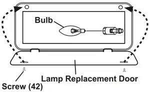
- Open the Lamp Replacement Door on the rear of the Heater by removing the Screws. See Figure C.
Figure C
- Replace the Bulb with a new bulb described under Specifications section on page 2.
WARNING! TO PREVENT SERIOUS INJURY:
Do not use a different type of light bulb or one with output greater than 40 watts to prevent fire. - Reattach Lamp Replacement Door with Screws.
WARNING! TO PREVENT SERIOUS INJURY:
Do not operate this heater without the access panel in place. Do not remove back cover.
Troubleshooting
If the heater does not operate:
- a. Make sure that the heater is plugged in.
- b. Ensure that the outlet used is powered and that the circuit breaker is not tripped.
- c. Avoid the use of an extension cord. However, if you have to use an extension cord, the cord shall be No. 16 AWG minimum size and rated not less than 1500 watts.
- d. Check for any obstruction in the heater’s vents.
If an obstruction is found, unplug the heater and wait for it to cool completely.
Then, carefully remove the obstruction. - e. Make sure the heater is placed on an even surface. Uneven surfaces may activate the heater’s tip-over switch, which turns the heater off.
If the above remedies do not solve the problem, take the heater to a qualified service technician for diagnosis and repair.
Parts List and Assembly Diagram
PLEASE READ THE FOLLOWING CAREFULLY
THE MANUFACTURER AND/OR DISTRIBUTOR HAS PROVIDED THE PARTS LIST AND ASSEMBLY DIAGRAM IN THIS MANUAL AS A REFERENCE TOOL ONLY. NEITHER THE MANUFACTURER OR DISTRIBUTOR MAKES ANY REPRESENTATION OR WARRANTY OF ANY KIND TO THE BUYER THAT HE OR SHE IS QUALIFIED TO MAKE ANY REPAIRS TO THE PRODUCT, OR THAT HE OR SHE IS QUALIFIED TO REPLACE ANY PARTS OF THE PRODUCT. IN FACT, THE MANUFACTURER AND/OR DISTRIBUTOR EXPRESSLY STATES THAT ALL REPAIRS AND PARTS REPLACEMENTS SHOULD BE UNDERTAKEN BY CERTIFIED AND LICENSED TECHNICIANS, AND NOT BY THE BUYER. THE BUYER ASSUMES ALL RISK AND LIABILITY ARISING OUT OF HIS OR HER REPAIRS TO THE ORIGINAL PRODUCT OR REPLACEMENT PARTS THERETO, OR ARISING OUT OF HIS OR HER INSTALLATION OF REPLACEMENT PARTS THERETO.
Parts List
Part | Description | Qty. | Part | Description | Qty. | |
| 1 | Lamp Replacement Door | 1 | 22 | Synchronous Motor | 1 | |
2 | Plate | 1 | 23 | Roller Sleeve | 1 | |
| 3 | Plate Frame | 1 | 24 | Reflector Roller | 1 | |
4 | Light Buble Socket Bracket | 1 | 25 | Fan Motor | 1 | |
| 5 | Plate Strip | 1 | 26 | Heating Element | 1 | |
6 | Left Side Plate | 1 | 27 | Close-end Connector | 3 | |
| 7 | Left Synchronous Motor Support | 1 | 28 | Foot | 4 | |
8 | Frame | 1 | 29 | Wiring Terminal | 1 | |
| 9 | Plate Batten | 1 | 30 | Power Cord | 1 | |
10 | Right Synchronous Motor Support | 1 | 31 | Cord Fastener | 1 | |
| 11 | Right Side Plate | 1 | 32 | Single Plug Spring | 14 | |
12 | Outside Glass Strip | 1 | 33 | Power Line Deduction | 1 | |
| 13 | Terminal Support | 1 | 34 | Screw | 1 | |
14 | Motor Box | 1 | 35 | Light Bulb Socket | 1 | |
| 15 | Upper Cover | 1 | 36 | Tieline Buckle | 7 | |
16 | Upper Cover Plate | 1 | 37 | Light Bulb | 1 | |
| 17 | Reflection Panel | 1 | 38 | Retaining Coil | 2 | |
18 | Back Cover | 1 | 39 | Rocker Switch | 3 | |
| 19 | Glass | 1 | 40 | Knob | 1 | |
20 | Resin Log | 1 | 41 | Bolt* | 12 | |
| 21 | Base Plate | 1 | 42 | Screw* | 2 |
Record Product’s Serial Number Here:
Note: If product has no serial number, record month and year of purchase instead.
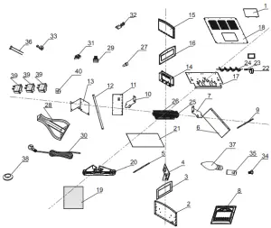
Note: Some parts are listed and shown for illustration purposes only, and are not available individually as replacement parts. Specify UPC 193175038890 when ordering parts.
Assembly Diagram
Limited 90 Day Warranty
Harbor Freight Tools Co. makes every effort to assure that its products meet high quality and durability standards, and warrants to the original purchaser that this product is free from defects in materials and workmanship for the period of 90 days from the date of purchase. This warranty does not apply to damage due directly or indirectly, to misuse, abuse, negligence or accidents, repairs or alterations outside our facilities, criminal activity, improper installation, normal wear and tear, or to lack of maintenance. We shall in no event be liable for death, injuries to persons or property, or for incidental, contingent, special or consequential damages arising from the use of our product. Some states do not allow the exclusion or limitation of incidental or consequential damages, so the above limitation of exclusion may not apply to you. THIS WARRANTY IS EXPRESSLY IN LIEU OF ALL OTHER WARRANTIES, EXPRESS OR IMPLIED, INCLUDING THE WARRANTIES OF MERCHANTABILITY AND FITNESS.
To take advantage of this warranty, the product or part must be returned to us with transportation charges prepaid. Proof of purchase date and an explanation of the complaint must accompany the merchandise. If our inspection verifies the defect, we will either repair or replace the product at our election or we may elect to refund the purchase price if we cannot readily and quickly provide you with a replacement. We will return repaired products at our expense, but if we determine there is no defect, or that the defect resulted from causes not within the scope of our warranty, then you must bear the cost of returning the product. This warranty gives you specific legal rights and you may also have other rights which vary from state to state.
Specifications
Electrical Input | 120VAC / 60Hz / 12A |
Heat Settings | 750W / 1500W |
| Light Bulb Type | 40W Type E-12 Candelabra |

US
253158

26541 Agoura Road • Calabasas, CA 91302 • 1-888-866-5797
![]()
Read this material before using this product. Failure to do so can result in serious injury. SAVE THIS MANUAL.
When unpacking, make sure that the product is intact and undamaged. If any parts are missing or broken, please call 1-888-866-5797 as soon as possible.
Copyright© 2020 by Harbor Freight Tools®. All rights reserved. No portion of this manual or any artwork contained herein may be reproduced in any shape or form without the express written consent of Harbor Freight Tools. Diagrams within this manual may not be drawn proportionally. Due to continuing improvements, actual product may differ slightly from the product described herein.
Tools required for assembly and service may not be included.
Visit our website at: http://www.harborfreight.com
Email our technical support at: [email protected]


