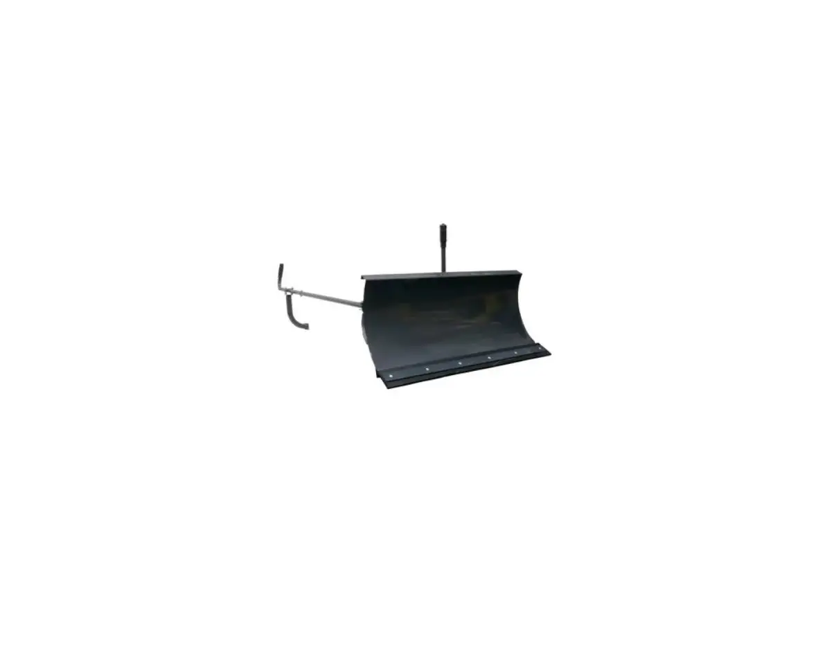
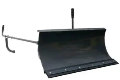
TOPMAQ 31455 Optional Plow Blade
MODEL NUMBER : 31455
SERIAL NUMBER :
Both model number and serial number may be found on the main label.
You should record both of them in a safe place for future use.
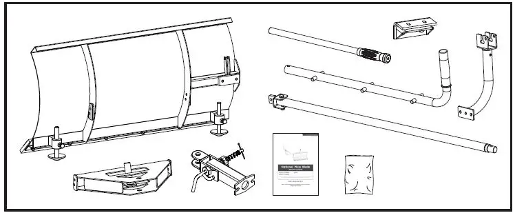
CONTENTS SUPPLIED
The plow blade comes partially assembled and is shipped in carefully packed package. After all the parts have been removed from the package, you should have:
ASSEMBLY OF OPTIONAL ACCESSORIES
This mini tracked dumper was completely assembled at the factory. To assemble the optional plow blade follow the below instructions.
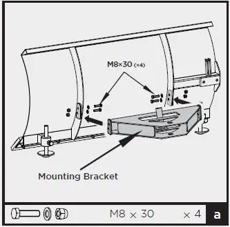
Plow Blade (Optional)
- Mount the mounting bracket to the blade using M8×30 hex bolts, washers and nuts.

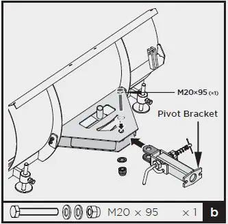
- Position the pivot bracket inside the mounting bracket and align with mounting bracket holes. Secure with M20×95 hex bolt, washers and nut.

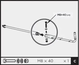
- Insert the shorter control lever into the longer lever. Align holes and fasten with M8×40 hex bolt, washers and nut.

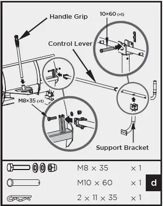
- Attach control lever to the guide tube.
Line up holes and fasten with M8×35 bolt, washers and nut. - Insert the handle grip into the holder.
- Secure the support bracket into the control lever with pin 10×60 and bridge clip.

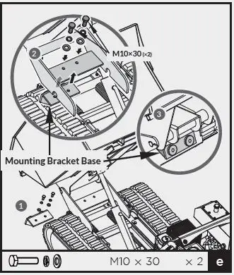
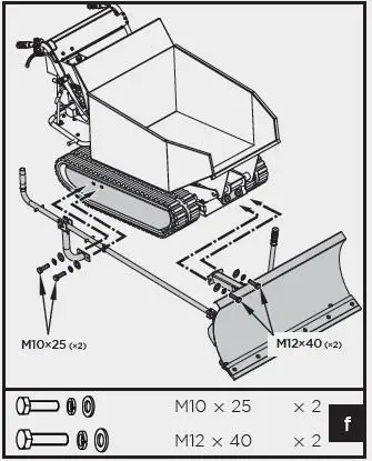
- Install the mounting bracket base with two M10×30 bolts and washers.

- Install the already assembled plow blade to the trackbarrow as shown.
PARTS SCHEDULE
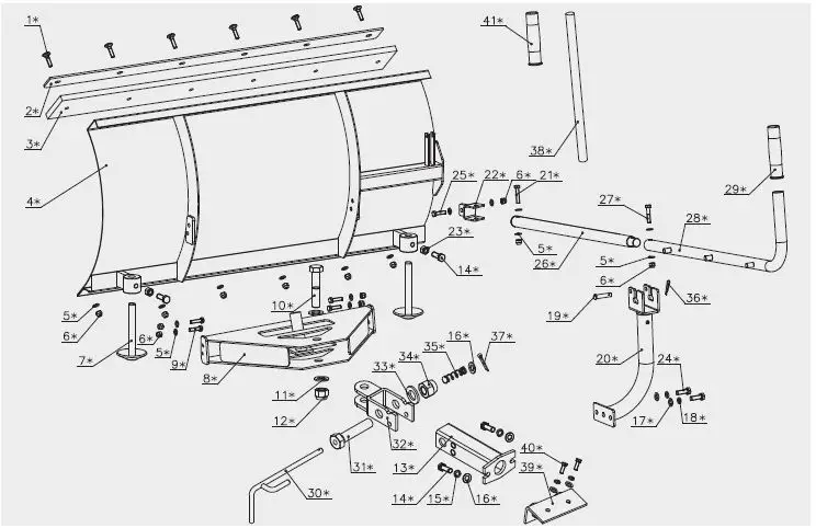
| No. | Description | Q’ty |
| 1 | Bolt M8×35 | 6 |
| 2 | Shave Plate | 1 |
| 3 | Rubber Plate | 1 |
| 4 | Blade Weldment | 1 |
| 5 | Washer8 | 16 |
| 6 | Nut M8 | 13 |
| 7 | Landing Leg Weldment | 2 |
| 8 | Blade Fixed Bracket Weldment | 1 |
| 9 | Bolt M8×30 | 4 |
| 10 | Bolt M20×95 | 1 |
| 11 | Washer 20 | 2 |
| 12 | Nut M20 | 1 |
| 13 | Blade Connecting Bracket Weldment | 1 |
| 14 | Bolt M12×40 | 4 |
| 15 | Washer 12 | 2 |
| 16 | Washer 12 | 3 |
| 17 | Washer 10 | 4 |
| 18 | Washer 10 | 4 |
| 19 | Pin 10×60 | 1 |
| 20 | Curved Support Bracket Weldment | 1 |
| No. | Description | Q’ty |
| 21 | Bolt M8×50 | 1 |
| 22 | Active Connecting Weldment | 1 |
| 23 | Nut M12 | 2 |
| 24 | Bolt M10×25 | 2 |
| 25 | Bolt M8×35 | 1 |
| 26 | Adjusting Rod Weldment B | 1 |
| 27 | Bolt M8×40 | 1 |
| 28 | Adjusting Rod Weldment A | 1 |
| 29 | Handle Sleeve 28 | 2 |
| 30 | Limiter Rod Wedment | 1 |
| 31 | Bolt M24×110 | 1 |
| 32 | Limiter Weldment | 1 |
| 33 | Washer24 | 1 |
| 34 | Lock Nut M24 | 1 |
| 35 | Spring | 1 |
| 36 | Bridge Pin 2×11×35 | 1 |
| 37 | Pin 4×40 | 1 |
| 38 | Handle Grip 2 | 1 |
| 39 | Bended Plate | 1 |
| 40 | Bolt M10×30 | 2 |
| 41 | Handle Sleeve 25 | 1 |


