![]() LED Lighting Fixture
LED Lighting Fixture
Installation Guide
MWP2 LED Lighting Fixture
![]() BEFORE YOU BEGIN
BEFORE YOU BEGIN
Read and follow all safety instructions![]() WARNING
WARNING
RISK OF FIRE, EXPLOSION AND ELECTRIC SHOCK
![]()
- This product should be installed, inspected, and maintained by a qualified electrician only, in accordance with the NEC (National Electric Code) and all local codes.
- Turn off electrical power before inspection, installation or removal.
- Use only UL (or other NTRL) approved wire for input/output connections.
- Minimum size 18 AWG or 14 AWG for continuous runs.
- Make sure LEDs and drivers are cool to touch when performing maintenance.
- Make sure the supply voltage is the same as the rated voltage of the luminaire.
- Do not install in a hazardous atmosphere, except where the ambient temperature does not exceed the rated operating temperature of the fixture.
- Keep tightly closed when in operation
Prepare Electrical Wiring
Electrical Requirements
 The LED driver must be supplied with the voltage specified on the product label and connected to an individual, properly grounded branch circuit protected by a 20 Ampere circuit breaker. Use min. 75°C supply.
Grounding Instructions
 The grounding and bonding of the overall system shall be done in accordance with NEC Article 600 and local codes
Medium Wall Pack, Gen-2
Tools Required:
| Drill | Wire Strippers5/16″ |
| Drill bit | Wire Cutters |
| 1/4″ Bit Driver | Assorted driver bits |
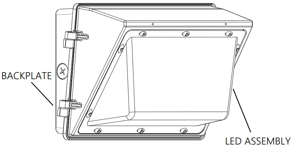
- Open the fixure by loosening the two (2) tamper-proof screws on the side of the housing.
- Disconnect the LED module power leads from the LED driver and remove the LED assembly. Do not drop or mishandle the LED assembly.
- Prepare the back plate for mounting by drilling or knocking out the appropriate holes. Item A on Fig. 1.
- Line up the back plate in the desired location and mount securely. LED driver assembly may need to be removed.
- Apply silicone caulking around the back plate between the mounting surface for a weather-tight seal.
- Reattach the LED driver assebly to the back plate.
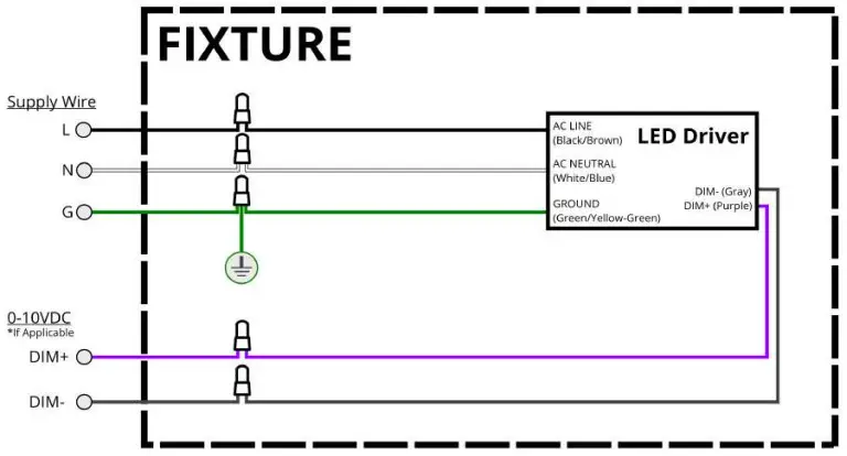
- Wire the fixture leads to the supply leads per Fig. 2 below.
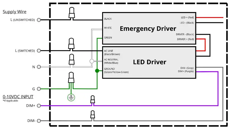
** For EM: Please refer to the wiring diagram on Fig. 3 below. Supply power to the fixture. Connect the battery plug to the EM. Turn off the wall switch to the fixture. - Reattach the LED module power leads to the driver and replace the LED assembly using the provided tamper-proof screws.
- For EM fixture, press the test button on the side of the fixture to make sure EM is functioning properly.
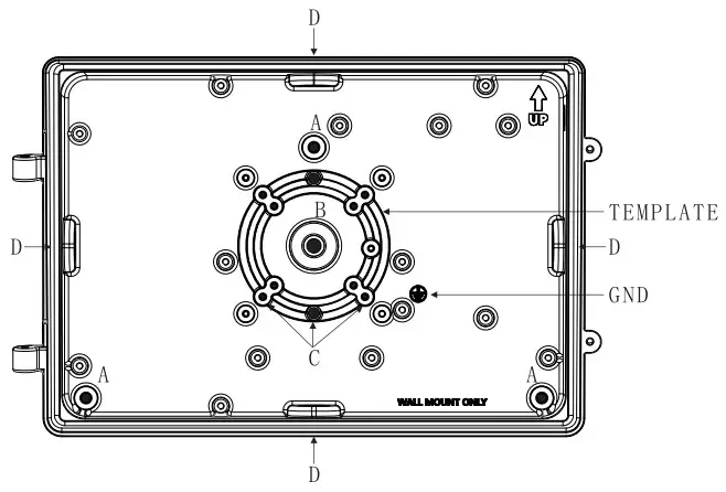
FIG.1
MOUNTING:
The back plate has a cast-in drill and knock-out template to match any standard recessed junction box, three 5/16” knockouts for mounting holes A and three 1/2” NPS tapped holes D for surface conduit or photocontrol unit.
A – 5/16” dia. Knockouts
B – 9/16” dia. Knockouts
C – Knockouts for #10 screw
D – 1/2” NPS tapped holes.
Medium Wall Pack, Gen-2
Electrical Wiring Diagram – Figure 2 | Electrical Wiring Diagram With EM Backup – Figure 3 |
 |  |
 https://www.howard-lighting.com/index.cfm
SAVE THESE INSTRUCTIONS


