T D TR72A-S Thermo Recorder User Manual
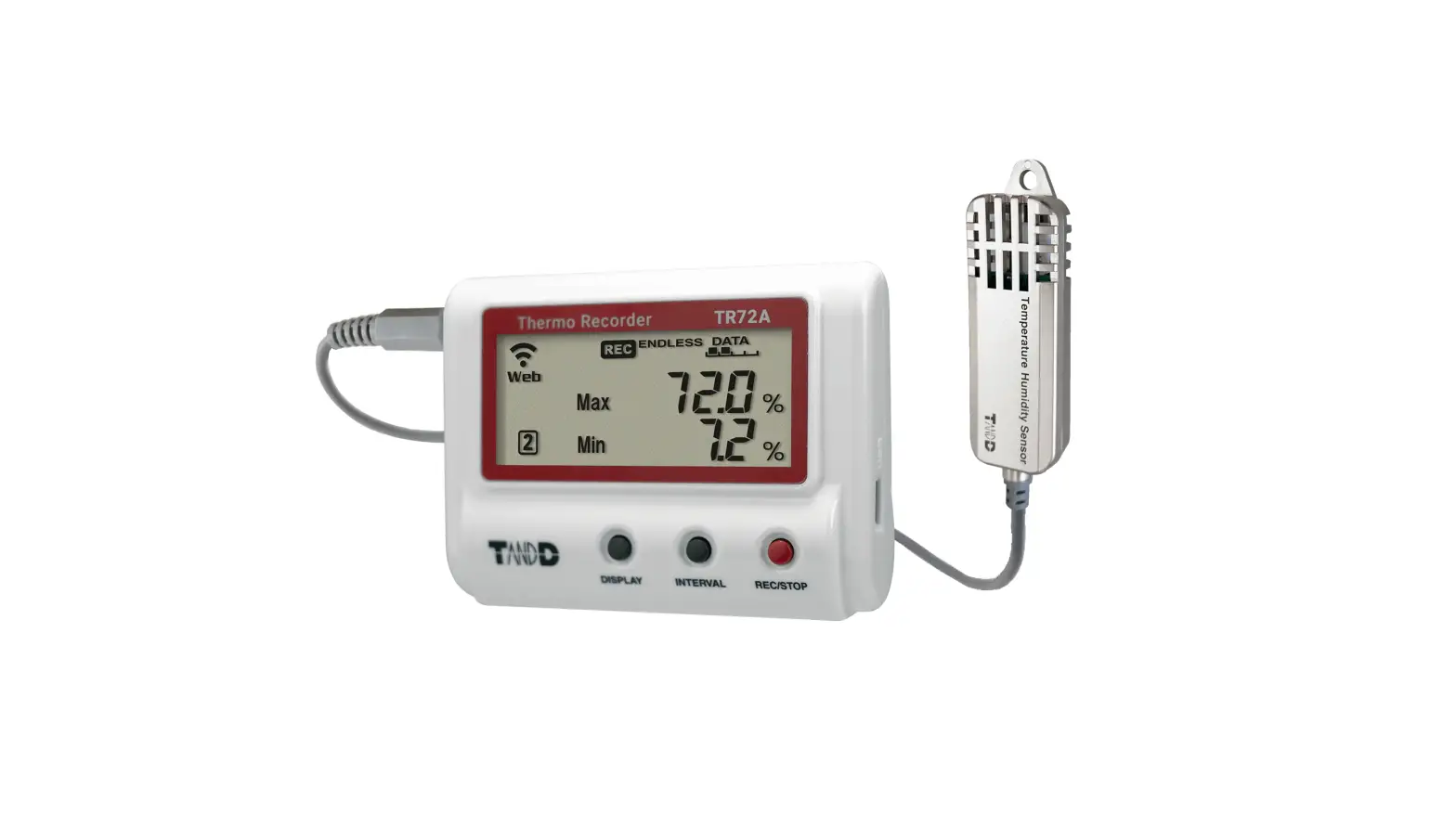
TR71A / TR72A / TR72A-S are data loggers for measuring and recording temperature and humidity. Device settings are made on a PC via USB cable. The recorded data can be either directly downloaded to a PC or automatically uploaded to the cloud service via wireless LAN. By using the cloud service, it is possible to receive a warning notification by email when a deviation such as temperature excursion is detected.
Also, the TR71A has a vaccine mode that is useful for managing vaccine temperature. The vaccine mode can be set using the PC software “TR7 for Windows”.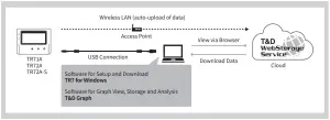
In this document, TR71A, TR72A and TR72A-S are collectively referred to as the “TR7A Series” or simply as the “device” or “logger”.
TR71A Operational Differences by Mode
Normal Mode | Vaccine Mode | |
Max / Min Values | Refresh at newly measured value | Refresh at newly recorded value |
| Warning Judgment Time | 30 sec to 60 min (9 selections) A warning will be issued when a measurement exceeds the set threshold value or a sensor error occurs for longer than the set judgment time. | 0 sec. If a recorded value exceeds the set threshold value or if a sensor error occurs, a warning will be issued. |
Warning Display [ALM] Icon | Warning alarms for exceeding a set upper and lower limit and for sensor errors will both disappear when the warning condition is resolved. | Warning alarms for exceeding a set upper and lower limit will not disap- pear even after a value returns to within the threshold range. Warning alarms for sensor errors will disappear upon return to normal. |
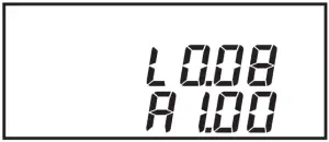
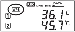
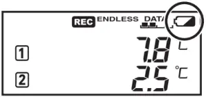
Marks on LCD Screen
| Wireless LAN ON : Connected to the wireless network. (Signal strength: 1 to 3 bars) BLINKING : Unable to connect to the wireless network. OFF : Wireless LAN Settings are not made or Auto-Upload is “OFF”. | |
| ON : Connected to the server. BLINKING : Unable to connect to the server. OFF : Wireless LAN Settings are not made or Auto-Upload is “OFF”. | |
| Displayed Measurement Channel | |
| ON : Wireless LAN Setup using WPS Possible | |
| ON : Connected via LAN or USB. BLINKING : LAN or USB communication in Progress | |
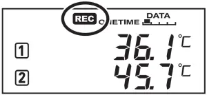
 | ON : Recording in Progress |
|
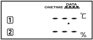
| ENDLESS : Upon reaching the logging capacity of 30,000 readings, the oldest data is overwritten and recording continues. ONETIME : Upon reaching the logging capacity of 30,000 readings, record- ing automatically stops. Cannot be set or changed using buttons on the logger. |
 | Amount of Recorded Data in Device |
|
| Battery Warning Mark BLINKING : Indicates low battery ON : Auto-upload will stop. (Recording will continue.)
|
| Auto Upload Interval | |
| Recording Interval | |
 | BLINKING : Indicates either upper/lower limit error or sensor error |
| Maximum and minimum values since the start of measurement or reset |


Messages on LCD Screen

Indicates a sensor error (No sensor connected, improper connection, damaged, etc.)
Recording Full (Recording Stopped)
This appears when the logging capacity (30,000 readings) is reached in “ONETIME”
mode.
Dead Battery (Recording Stopped)
This appears if, after the battery warning mark is displayed, no action is taken and the batteries run out.
Please refer to “About Battery Replacement” on the back of this document, and change the batteries.
If the dead batteries are not changed, the display will automatically shut off. The previously recorded data will remain saved.
The logger will then turn off the LCD display and reset the internal clock. Please refer to “About Battery Replacement” on the back of this document, and change the batteries.
Firmware Version
This appears immediately after the power is turned on.


Factory Default Settings
Recording Mode: Endless
Recording Interval: 10 min
Auto-Upload: OFF
Upload Destination: T&D WebStorage Service
Warning Settings: OFF
Max/Min Auto Reset: ON / every day at 0:00
Time Zone: GMT+1:00 for Serial Number “No.4XXXXXXX”
GMT-8:00 for Serial Number “No.3XXXXXXX”
Free Cloud Storage “T&D Web Storage Service”
“T&D WebStorage Service” is a free cloud-based storage service provided by T&D Corporation, which enables you to access the uploaded recorded data from a web browser and check the current readings, remaining battery life of the device, and alert status. You can also receive warning notifications by email. In order to use the “T&D WebStorage Service”, user registration (free) and device registration are required.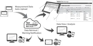
Important Notes
- Before registering as a user, please read [Service Details / License Agreement] for infor-mation on service contents and specifications, including the data storage period in the “T&D WebStorage Service”.
- The registration code of the device can be found on the supplied Registration Code Label. If you lose the code label, install the software “TR7 for Windows” and connect your logger via USB to the computer. The registration code and device information will be displayed at the lower-left area of the screen.
- When the storage period in “T&D WebStorage Service” is exceeded, old data will be deleted.
User and Device Registration Procedures
- Access “T&D WebStorage Service” from the web browser. https://www.webstorage-service.com/
- Click [Create Account] to go to the registration page, and follow the directions to complete the registration.
- Login by entering the registered User ID and Password.
- Click [Devices] in the left menu to open the Device Settings window. 5. Clicking the [+Device] button will take you to the Add a Device page. 6. Enter the serial number and registration code for the device, then click [Add].
Device Settings using Windows Software
Software Installation
- Download “TR7 for Windows” from the T&D Website and install it to your PC.
tandd.com/software/tr7win.html - Connect the TR7A Series device via USB to your computer.
“TR7 for Windows” will open automatically. (If not, please open it manually from the Windows Start Menu or Start Screen.)
Clock Settings
Open [Clock Settings] from the [Settings] menu, and make necessary settings related to the time.
Auto-Adjustment
Select [Auto-Adjustment] when using the Autoupload to automatically send the recorded data to the “T&D WebStorage Service”, or select [Set to Computer Clock] when using a USB connection to download data to your PC.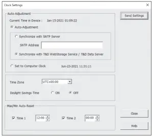
Time Zone
Specify the region where the device will be used.
Default Setting
GMT +1:00 (for serial number “No.4XXXXXXX”)
GMT -8:00 (for serial number “No.3XXXXXXX”)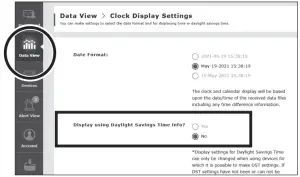
When turning on the Daylight Saving Time option in the Clock Settings for the device that automatically sends data to the “T&D WebStorage Service”, you need to access “T&D WebStorage Service” from your browser and go to [View Data] – [Clock Display Settings] and set the [Display using Daylight Savings Time info?] to “Yes”.
Max/Min Auto Reset
The TR7A Series has a function to automatically reset the maximum and minimum values on the LCD at specific time(s) of the day. If necessary, change the auto-reset setting, reset time and frequency.
Default Setting: ON / 0:00 every day
Recording Settings
Click the [Start Recording] tab and make necessary settings for recording.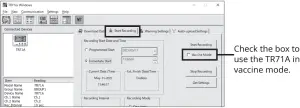
Setting Items which can be set or changed in [Start Recording] tab:
Recording Start Method (Programmed Start or Immediate Start), Recording Interval, Recording Mode, Group Name, Device Name, Channel Name
Recording Interval in Vaccine Mode
- In the vaccine mode, warning judgments are made on the recorded value at the interval set for recording on the logger.
- 60-min interval is not available.
References:
Recording Intervals & Estimated Maximum Recording Times
| Recording Interval | 1 sec. | 30 sec. | 5 min | 10 min (default) | 15 min | 60 min |
| Estimated Time | About 8 hours | About 10 days | About 100 days | About 200 days | About 1 year | About 3.5 years |
Recording Intervals & Corresponding Maximum Length (in days) of Data Stored in T & D WebStorage Service
| Recording Interval | 1 sec. | 2 sec. | 5 sec. | 10 sec. | 15 sec. | 20 sec. | 30 sec. | 1 min. | 2 min. | 5 min. | 10 min. | 15 min. | 20 min. | 30 min. | 1 hr. |
| Maximum Length (in days) | 1 day | 2 days | 3 days | 6 days | 9 days | 12 days | 20 days | 30 days | 80 days | 200 days | 450 days | 450 days | 450 days | 450 days | 450 days |
Warning Settings
Click the [Warning Settings] tab and make the necessary settings. By making warning settings, you will see the blinking on the LCD screen of the logger when a deviation such as temperature excursion is detected. You can also receive a warning email from “T&D WebStorage Service” by making Wireless LAN Settings in the “Auto-Upload Settings”. Warning mail recipients can be set in the “T&D WebStorage Service”.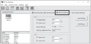
Setting Items which can be set or changed in [Warning Settings] tab:
Lower Limit, Upper Limit, Sensor Warning, Judgment Time, Battery Warning
By changing the temperature unit to Fahrenheit in [Settings] – [Temperature Unit Settings] menu, the upper and lower limits can be set in Fahrenheit here.
Warning Judgment Time in Vaccine Mode
- In the vaccine mode, warning judgments are made on the recorded value at the interval set for recording on the logger. (Warning Judgment Time is fixed to 0 sec. and cannot be changed.)
Auto-Upload Settings
To automatically send the recorded data to “T&D WebStorage Service” or to use the warning mail function, configure the Wireless LAN Settings in the [Auto-upload Settings] tab.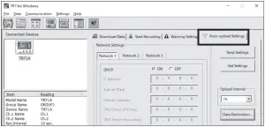
Setting Items which can be set or changed in [Auto-upload Settings] tab:
DHCP, Wireless LAN Settings, Proxy Server, Upload Interval, Data Destination, Clock Settings
Ref: Auto-Upload Intervals & Corresponding Estimated Battery Life
In general, the shorter the upload interval, the shorter the battery life.
| Upload Interval | 1 min | 10 min | 1 hr | 12hrs or more |
| Battery Life | About 10 days | About 2 months | About 1 year | About 15 months |
- All estimates are based on operations carried out with a new battery and are in no way a guarantee of actual battery life.
- When Auto-upload is used frequently on TR71A, the measurement of the internal sensor may rise by around 0.3°C.
Applying Settings
- Click the [Send Settings] button on the [Warning Settings] tab or the [Auto-upload Settings] tab to send the settings to the device. The settings can also be applied by clicking the [Start Recording] button in the [Start Recording] tab.
- Upon the start of a new recording session all stored data will be deleted from the device.
- Place the device in the measurement location.
Checking Connection Status (for Auto-upload)
Place the logger in the desired measurement location where Internet access is available.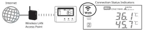
Press the <REC/STOP> button on the logger to immediately send the recorded data to “T&D WebStorage Service” without waiting for the next transmission.
If the transmission is successful, ![]() and
and![]() will remain ON after
will remain ON after![]() turns OFF.
turns OFF.
 is OFF or blinking: Unable to connect to the wireless network. Try adjusting the position of the device or its distance from the access point, or check the access point settings.
 is blinking: Internet connection failed. Please check the access point’s internet connection.
When using auto-upload to the cloud, sending the setting changes will not be actually applied on the “T&D WebStorage Service” screen until communication occurs between the TR7A Series and “T&D WebStorage Service”. By pressing the <REC/STOP> button on the logger, however, settings can be applied immediately.
Viewing Recorded Data
There are mainly two ways to view, analyze, and manage recorded data, and they can be used in combination.
Via PC: Download with a USB Connection
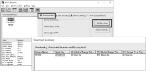
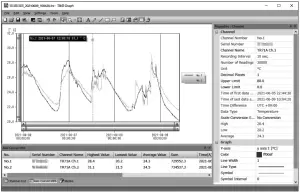
By connecting the TR7A Series to a PC via USB, it is possible to download recorded data. Data downloaded can then be viewed in a graph for analysis by using the software “T&D Graph”.
- Download “T&D Graph” from the T&D Website and install it to your PC. tandd.com/software/td-graph.html
- Connect the TR7A Series via USB to your computer.
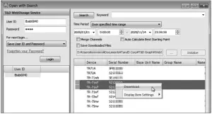
- Open “TR7 for Windows”, click on the [Download Data] tab and proceed with the download.

Upon completion of download, the summary (such as total time out of range) will be displayed.
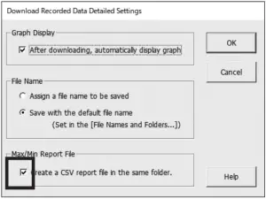
If necessary, settings for “Graph Display” and “File Name” can be viewed and changed under [Detailed Settings]. When the [Create a CSV report file in the same folder] option is checked, a report file (CSV) that contains the maximum, minimum, and average values for each day and the total time of deviation will be saved in the same location as the recorded data.
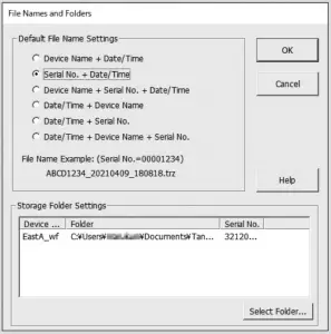
Storage Location of Recorded Data
The recorded data downloaded by “TR7 for Windows” will be saved in the following location on your computer.
Folder Name: “TandD Corp\TR7 for Windows” in “Documents” or “My Documents”
The storage location can be viewed or changed from the [File] menu – [File Names and Folders] option.
- If you check the [After downloading, automatically display graph] option in the [Download Data] tab – [Detailed Settings], “T&D Graph” will automatically open and display the graph after the download is complete.

For details about operations please see the “Help” menu in the “T&D Graph”.
Via Cloud: Viewing Data in a Browser
When using auto-upload to “T&D WebStorage Service”, uploaded data can be viewed on a web browser by accessing the following URL.
https://www.webstorage-service.com/
[Data View] Menu
You can view data such as battery status, measurement, and last update date (relative date and time). Click [Details] to open a graph.![[Data View] Menu](https://static-data1.manualsee.com/1/img/203/1863252/2022/01/Screenshot_33-98-300x157.png)
[Devices] Menu
You can check the recording interval, auto-upload interval, and warning ON/OFF settings. Click the [Settings] button to open the individual [Device Settings] screen with device information and warning setting details.
For the TR72A, TR72A-S, and the TR71A that is not set to vaccine mode, the settings can also be changed in this screen.![[Devices] Menu](https://static-data1.manualsee.com/1/img/203/1863252/2022/01/Screenshot_34-85-300x278.png)
Setting Items which can be viewed or changed in individual Device Settings:
Device Name, Group Name, Recording Interval, Recording Mode, Auto-upload Interval, Time Difference, Daylight Saving Time, Temperature Unit, Channel Name, Upper Limit, Lower Limit, Sensor Warning, Judgment Time, Battery Warning
Note that the setting changes will not be actually applied until communication occurs between the logger and “T&D WebStorage Service”. By pressing the <REC/STOP> button on the logger, however, settings can be applied immediately.
Via Cloud: Viewing Data in “T&D Graph”
The recorded data sent to “T&D WebStorage Service” can also be viewed
using the software “T&D Graph”.
- Download “T&D Graph” from the T&D Website and install it to your PC. tandd.com/software/td-graph.html
- Open “T&D Graph” and go to the [File] menu – [Web Storage Service].
- Enter the “User ID” and “Password” you have registered with “T&D WebStorage Service”.
- Click the [Login] button. Upon successful login, all recorded data stored in “T&D WebStorage Service” will be displayed.

- Double click on the recorded data you wish to view in a graph. The data will be downloaded and displayed in a graph.
- If you wish to merge multiple sets of data into one graph, select multiple files and click [Download] from the right-click menu.
- For details about operations please see the “Help” menu in the “T&D Graph”.
| Power ON/OFF | Press-and-hold*1 the <PWR> button. |
| Start*2 / Stop Recording | Press-and-hold the <REC/STOP> button. |
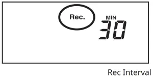
| Check Recording Interval / Upload Interval | Press the <INTERVAL> button. With each pressing of the button, the display will switch between the recording interval ( ) and the upload interval ( ). |
| Recording Interval Setting | Press the <INTERVAL> button. While is dis- played, press-and-hold*3 the <INTERVAL> button until the interval time flashes. Press <INTERVAL> again to select the interval time. |
| Upload Interval Setting | Press the <INTERVAL> button twice. While is displayed, press-and-hold the <INTERVAL> button until the interval time flashes. Press <INTERVAL> again to select the interval time. |
| Transmit Data and Settings to “T&D WebStorage Service” | Press the <REC/STOP> button. |
| Cancel Communication | Press the <PWR> button. |
| Switch Display Items and Pattern (Fixed or Alternating Display) | Press the <DISPLAY> button. Each pressing of the button will change the display items and pattern (fixed or alternating display) as shown below: Ch1/Ch2 current values (fixed) Ch1 MAX/MIN values (fixed) Ch2 MAX/MIN values (fixed) alternating display |
| Clear Max/Min (and ALM) | While Max/Min (and ALM) are displayed (in fixed display), press-and-hold the <DISPLAY> button. |
| Wireless LAN Settings using WPS | Press-and-hold <PWR> and <DISPLAY> together. |
- “Press-and-hold” means to hold the button down for about two seconds. During recording, the power cannot be turned off.
- Upon the start of recording, all previously recorded data in the unit will be deleted.
- Recording Interval setting cannot be changed while a recording session is in progress.
Before performing button operations, please read the attached document “Please Read First” and install the batteries and sensor(s) in the logger, and make sure the LCD is displaying measurements.
Recording Interval Setting
Follow the steps below to change the recording interval using the buttons on the device. The factory default setting is 10 minutes.
 Upon the start of recording, all previously recorded data in the logger will be deleted.
- Note: When 0 is ON (recording in progress), the logger cannot be turned off, nor can the recording interval be changed.
 Upon the start of recording, all previously recorded data in the logger will be deleted.
- When
 is ON, press-and-hold the <REC/STOP> button until turns OFF (recording stops).
 - Press the <INTERVAL> button.

- While Rec. is displayed, press-and-hold the <INTERVAL> button until the interval time flashes.
- Press the <INTERVAL> button. Recording Intervals (Rec.) 1, 2, 5, 10, 15, 20, 30 SEC / 1, 2, 5, 0, 15, 20, 30, 60 MIN
- When the desired recording interval appears, stop pressing the button.
Within a few seconds, the display will return to measurement mode to indicate the upload interval is set.
- Press-and-hold the <REC/STOP> button. will turn on and recording will start.
Auto-upload Interval Setting
Follow the steps below to change the auto-upload interval using the buttons on the device. The factory default setting is OFF (no auto-upload).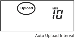
- Press the <INTERVAL> button twice to display the auto-upload interval.
- While Upload is displayed, press-and-hold the <INTERVAL> button until the interval time flashes.
- Press <INTERVAL> again to select the interval time. Each press changes the interval as follows: Auto-upload Intervals (Upload): OFF / 1, 2, 5, 10, 15, 20, 30 MIN / 1, 2, 3, 4, 6, 12, 24 HOUR
- The interval time will stop flashing and the display will return to the normal measurement mode, confirming that it is set.
Wireless LAN Connection using WPS
This function is not available if your wireless LAN access point does not support WPS or the security setting is other than WPA/WPA2 PSK.
What is the WPS?
WPS (Wi-Fi Protected Setup) is a feature that makes it easy to set up a wireless LAN connection. It allows you to set up wireless LAN communication between the TR7A Series and a wireless access point (router) that supports WPS with just a push of a button on the logger. Button name of the WPS may differ depending on the router. For details about operating WPS on the wireless LAN access point device, please check the User’s Manual that came with the unit.
- Press the <PWR> and <DISPLAY> buttons together until
 appears on the LCD screen.
 - Set your wireless LAN access point to “WPS” mode.
For details about Wireless LAN Access Point settings, refer to the user manual for that access point - When the wireless LAN connection is successfully established, the mark on the LCD display will turn ON.
Checking Connection Status
Place the logger in the desired measurement location where Internet access is available.
Press the <REC/STOP> button on the logger to immediately send the recorded data to “T&D WebStorage Service” without waiting for the next transmission. If the transmission is successful, ![]() , and
, and ![]() will remain ON after
will remain ON after ![]() turns OFF.
turns OFF.
- is OFF or blinking: Unable to connect to the wireless network. Try adjusting the position of the device or its distance from the access point, or check the access point settings. (See [Device Settings using Windows Software] – [Auto-Upload Settings])
- is blinking: Internet connection failed. Please check the access point’s internet connection.
About Battery Replacement
Three stages of diminishing battery life are described below. It is recommended to replace the batteries at stage 1.
- When it is time for the battery to be replaced, a battery life warning mark will appear.

After Battery Replacement- Recording will continue as it was before the battery replacement.
- It is possible to download all saved recorded data.
- If you continue to use the device without replacing the batteries, the display will show this message and record-ing will stop.

After Battery Replacement- Recording will remain stopped until you start recording. However, if the device communicates with the “T&D WebStorage Service” and the recording data is successfully uploaded, recording will resume.
- It is still possible to download all saved recorded data. Please note that if you start recording before the recorded data is downloaded to a PC or uploaded to the server, all recorded data in the device will be lost.
- If the batteries are further left unchanged, the device will then turn off the LCD display and reset the internal clock.
After Battery Replacement- Recording will remain stopped until you start recording. However, if the device communicates with the “T&D WebStorage Service” and the recording data is successfully uploaded, it will automatically synchronize the clock with the server and resume the recording.
- If auto-upload is set to OFF, you will need to set the clock again.
- It is still possible to download all saved recorded data. Please note that if you start recording before the recorded data is downloaded to a PC or uploaded to the server, all recorded data in the device will be lost.

For More Information and Support
- Please refer to the TR7 for Windows HELP.
cdn.tandd.co.jp/g1b/html_help/tr7win-help-eng/
- Please contact the distributor from which you purchased the product. tandd.com/purchasing/