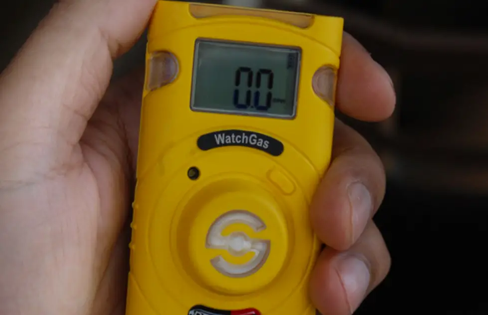
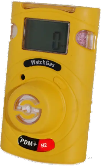
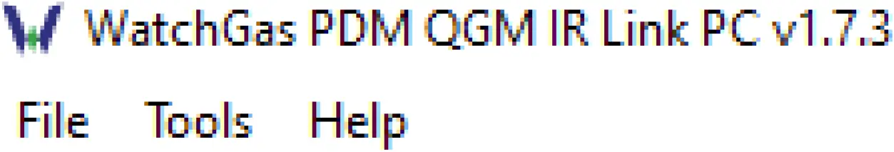
WatchGas PDM+ Single Sustainable Gas Detector
Description
PDM+ is a single sustainable gas detector designed to detect oxygen deficiency and presence of toxic gas in the ambient environment. The PDM+ is sustainable, hence its battery and sensor can be replaced. When turned on, PDM+ continuously monitors ambient air for the presence of a specific gas and alerts the user to potentially unsafe exposure with LED, vibrating, and audible alarms in the event that gas concentration exceeds alarm set points. The alarm set point, calibration range, and display configuration can be changed via WatchGas IR Link (Optional). After use, the instrument can be turned off.
Warning
- Any unauthorized attempt to repair or modify the product, or any other cause of damage beyond the range of the intended use, including damage by fire, lightening, or other hazard, voids liability of the manufacturer
- Activate this product only if sensor, visual, detection, and audible cover are clear from contaminants such as dirt and debris that could block the area where gas is to be detected
- Do not clean and rub the LCD screen of the products with a dry cloth or hands in hazardous environment to prevent the static electricity
- Perform cleaning and maintenance of the products in fresh air that is free of hazardous gases
- Test the response of a sensor regularly by the gas concentration exceeding alarm set point
- Test LED, audio and vibration manually
- Gas concentration measurements by the sensor can vary based on the environment (pressure and humidity) Therefore, calibration of PDM+ should be performed in the same (or similar) environment of the device’s actual use
- If the temperature changes sharply during use of the device (e g indoors vs outdoors), the value of the measured gas concentration can suddenly change Please use the PDM+ after the gas concentration value has stabilized
- Severe vibration or shock to the device may cause a sudden reading change Please use PDM+ after the value of gas concentration has stabilized Excessive shock to PDM+ can cause the device and/or sensor to malfunction
- All alarm value is set based on the alarm standard that is required by international standard. Therefore, alarm values should be changed only under the responsibility and approval of the administration of the work site where the instrument is used
- Use IR communications in the safety zone which is free of hazardous gases
- Replace the battery and sensor in clean environment, which is free of hazardous gas
Caution
- Before operating this device, please read the manual carefully.
- This device is not a measurement device, but a gas detector.
- If calibration and self-test fails continuously, please do not use the device.
- For the O2 detector, perform calibration every 30 days in the fresh air environment.
- Clean detectors with a soft cloth and do not use chemical substances for cleaning.
- To maintain 24 months battery life time, avoid the below activities except the necessary cases to check events(Max/Min), lifetime/concentration, and alarm set points. Otherwise, the frequent use of the button will deplete the battery lifetime less than 24 months.
- Push the button frequently without valid reasons.
- Frequent alarm operation or alarms are remained for a long time. *Normal Alarm Use: 1 time and 2 minutes per day.
WatchGas recommends to bump test the sensors before each day’s use to confirm their ability to respond to gas by exposing the detector to a known concentration of target gas that exceeds the alarm setpoints. Manually verify that the audible and visual alarms are activated. Calibrate the instrument if the readings are not within the specified limits.
Product Overview
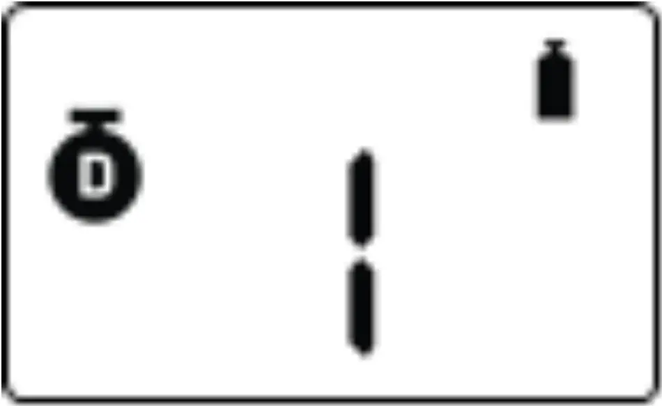
DETECTOR COMPONENTS
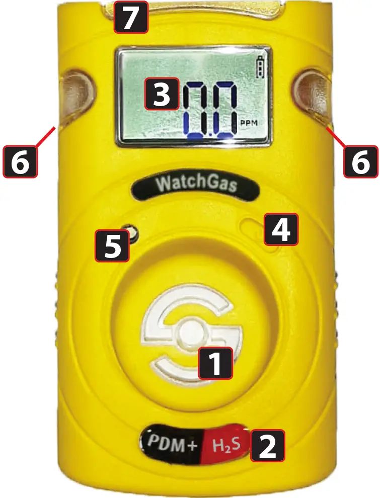
- Gas sensor
- Gas type sticker
- LCD display
- Button
- Buzzer
- Optical alarm LEDs
- IR communication port
DISPLAY SYMBOLS
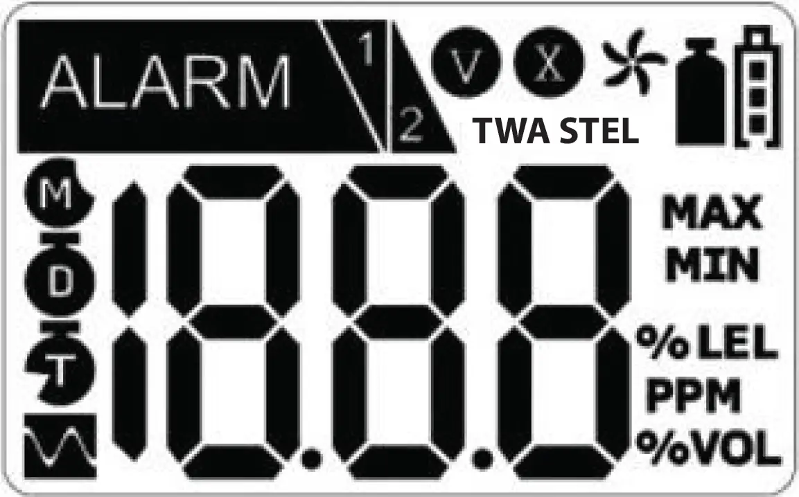
- Alarm
- Low Alarm
- High Alarm
- Stabilization Success
- Stabilization Fail
- Fresh Air Calibration
- Standard Gas Calibration
- Time Weighted Average
- Short Term Explosion Limit
- Remaining Months
- Remaining Days
- Remaining Time (Hours)
- Max Peak Value
- Min Peak Value
- Unit of Measurement
- Remaining battery life
Activation & Deactivation
ACTIVATION AND DEACTIVATION
In a safe environment, when pressing and holding the button for 3 seconds, gas type and firmware version (ex. v2.2) will be displayed. For 10 seconds countdown, the device will be stabilized. After stabilization is completed, the device will move to Detection mode.
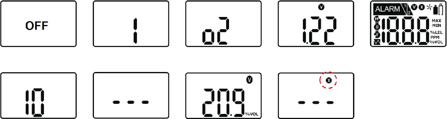
In the event that stabilization of the device fails, X will appear on the display and gas measurement mode will not be entered. In this case, perform calibration or contact authorized reseller for repair/return information.
To deactivate the device, pleas press and hold the key for countdown.
Caution
Although the PDM+ is calibrated before it leaves the factory, a proper calibration is advisable before using it at the work site. The user should check whether the device is properly detecting hazardous concentrations and make sure that the detecting section of the device is not blocked with materials impairing the detection.
Mode
MEASUREMENT MODE
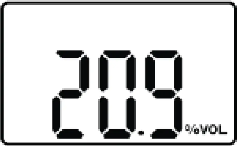
When activated, in measuring mode, gas concentration will appear on the screen. Oxygen concentration is displayed in percent by volume (%vol) and toxic concentration is displayed in parts per million (ppm).
DISPLAY MODE
In the Measuring Mode, by pressing key for one second, the following icons will appear in order:
MIN (only for oxygen) -> MAX -> STEL value -> TWA value-> Clr Max-> Clr TWA/STEL ->1st alarm set point –> 2nd alarm set point -> STEL setpoint -> TWA Set point-> Firmware version -> Remaining Calibration Day -> Calibration
Caution
Before changing alarm setpoints, please ensure the alarm set points are in compliance with your local guidelines. Option to manually change alarm setpoints can be unlocked using the IR-link.
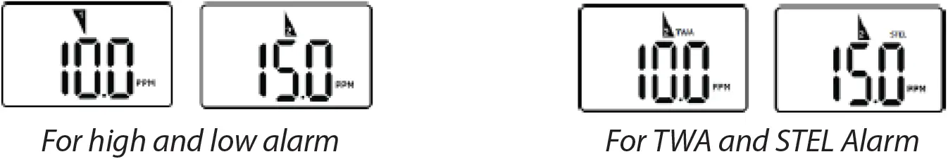
ALARM ACTIVATION & CONFIGURING ALARM SET POINTS
When a gas concentration exceeds alarm set points, 1 or 2 will be displayed and the device will vibrate, flash its LEDs, and beep. To stop alarms, evacuate immediately to a clean air location.
To configurate the alarm setpoints, please follow the steps below.
- Press the button until the above alarm setpoint is displayed
- Press and hold the button for three seconds and the first digit of alarm setpoint starts to blink
- To increase the value, press the button for one second
- To save the alarm setpoints, press the key for 3 seconds
* Ensure that the second alarm setpoint must be greater than first alarm setpoint.
DEFAULT ALARM SET POINTS
| Gas | O2 | CO | H2S | H2 | SO2 | NH3 | NO2 | H2O2 |
| Low alarm | 19% | 25 ppm | 5 ppm | 100 ppm | 1 ppm | 20 ppm | 5 ppm | 1 ppm |
| High Alarm | 23% | 25 ppm | 5 ppm | 100 ppm | 1 ppm | 20 ppm | 5 ppm | 1 ppm |
| STEL | – | 100 ppm | 3.2 ppm | – | 0.3 ppm | 50 ppm | 1 | 3 ppm |
| TWA | – | 20 ppm | 1.6 ppm | – | 0.3 ppm | 20 ppm | 0.5 ppm | 1 ppm |
Disclaimer: The default Set Points of these gases: H2, SO2, NH3 and NO2, are subject to change without notice.
Event Log
Last 30 events are stored on the PDM+. Once 30 events are stored, the oldest log events get overwritten. Stored log events can be transferred via WatchGas-IR Link.
Each alarm event is recorded as follows:
- Types of alarms
- Alarm concentration in ppm or %
- Peak concentration
- Alarm duration
Calibration
Caution
Initial calibration is performed on all devices prior to shipment. Once received, calibration should be regularly depending on frequency of use.
- Enter calibration menu.

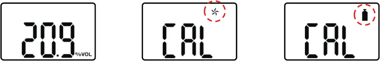
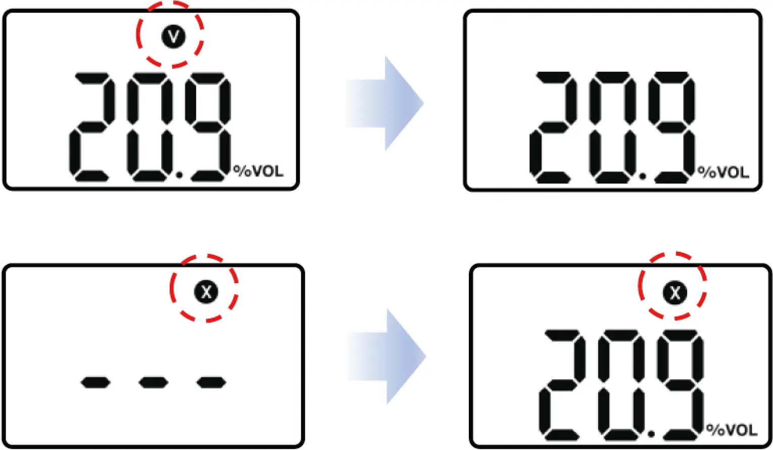
FRESH AIR CALIBRATION
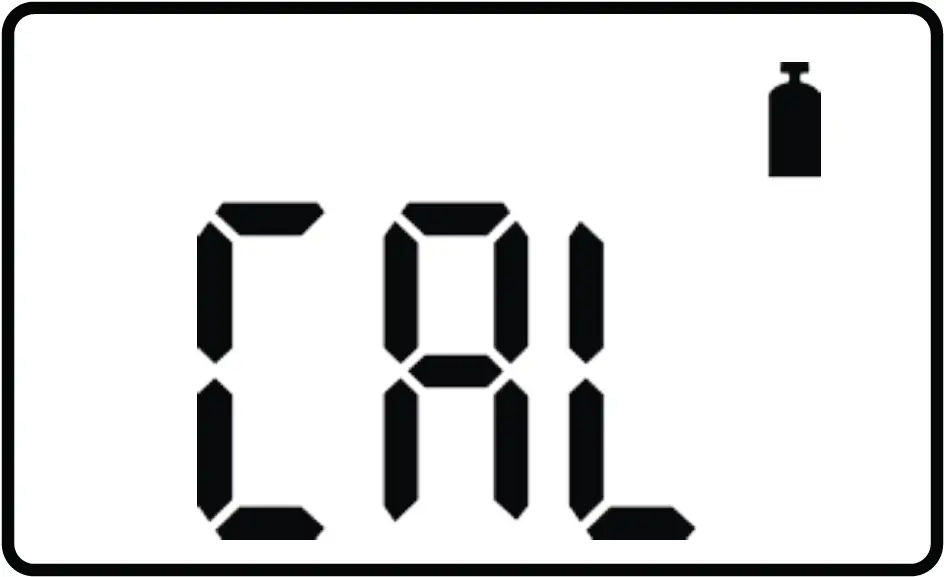
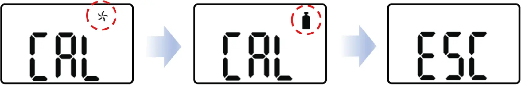
- Press and hold the key for 5 seconds to enter the calibration mode, icon and ‘CAL’ mark will appear on the LCD.
- Press the key for three seconds to initiate calibration. When calibration begins, a countdown (starting at 10) will appear on the screen.
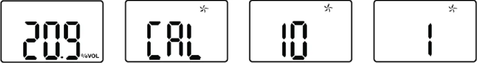
Once completed, V will appear on the LCD. The device will return to the calibration menu.
If calibration fails, X will appear on the LCD. Check that the air is clean and that no contaminants are blocking the sensor opening and try again. If fresh air calibration fails repeatedly, contact WatchGas. 5.2. STANDARD GAS
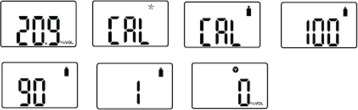
CALIBRATION
Attach the calibration adapter to the PDM+ and to a gas cylinder with a concentration matching the calibration concentration. Check 3.1. Display Mode to check the calibration concentration.
Press and hold the key for 5 seconds to enter calibration mode, icon and ‘CAL’ mark will appear on the LCD. Press the key again for a second when CAL is displayed, to switch to standard gas calibration, appears.
Start the flow of the gas cylinder by opening the valve.
Press the key for three seconds to initiate calibration. When calibration begins, a countdown will appear on the screen. The duration of the countdown depends on the sensor type and can be change by the IR link (configurable with WatchGas IR-Link). Confirm the calibration value by pressing the button once.
To set the calibration setpoints, please follow the steps below.
- Press the button until the above calibration setpoint is displayed.
- Press and hold the button for three seconds and the first digit of calibration setpoint starts to blink.
- To increase the value, press the button for one second .
- To save the calibration setpoints, press the button for 3 seconds.
- Calibration will start
Once completed, V icon will appear several seconds on the display. Then, the device will return to Detection mode.
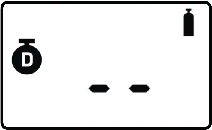
REMAINING CALIBRATION DAY
In Measuring mode, scroll through the menu by pressing the button until the following is displayed:
The default setting is “N/A”.
To activate the remaining calibration day, set an interval on the “Cal Interval(day)” via IR LINK.
If you set the calibration interval via IR LINK, the remaining day will be displayed. To check the remaining day, press the button until the above image is displayed.
Caution
Calibration should be performed in a fresh-air environment that is free for any contaminants and other gases. Preferably, do not perform calibration in a confined space.
CALIBRATION CONCENTRATION
Gas | O2 | CO | H2S | H2 | SO2 | NH3 | NO2 | H2O2 |
| Concentration | 0.0%Vol. (99,9% N2) | 100 ppm | 50 ppm | 500 ppm | 10 ppm | 100 ppm | 10 ppm | See our documentation on “Bump Test H2O2“ |
Once completed, V will appear on the LCD. After a few seconds, the PDM+ will return to Detection mode.
If calibration fails, X will appear on the LCD.
Check that the gas cylinder is not empty and that is has not expired. Also make sure that no contaminants are blocking the sensor opening and try again. If standard gas calibration fails repeatedly, contact WatchGas.
RETURN TO DETECTING MODE.
In the standard calibration mode, press the key for a second to toggle fresh air calibration, standard calibration, and ESC. In the ESC mode, press the key for 3 seconds, the PDM+ will get out of the calibration mode and return to Detection mode.
NOTE: Span calibration value can be change in the device and IR link software
Self Test & Bump Test
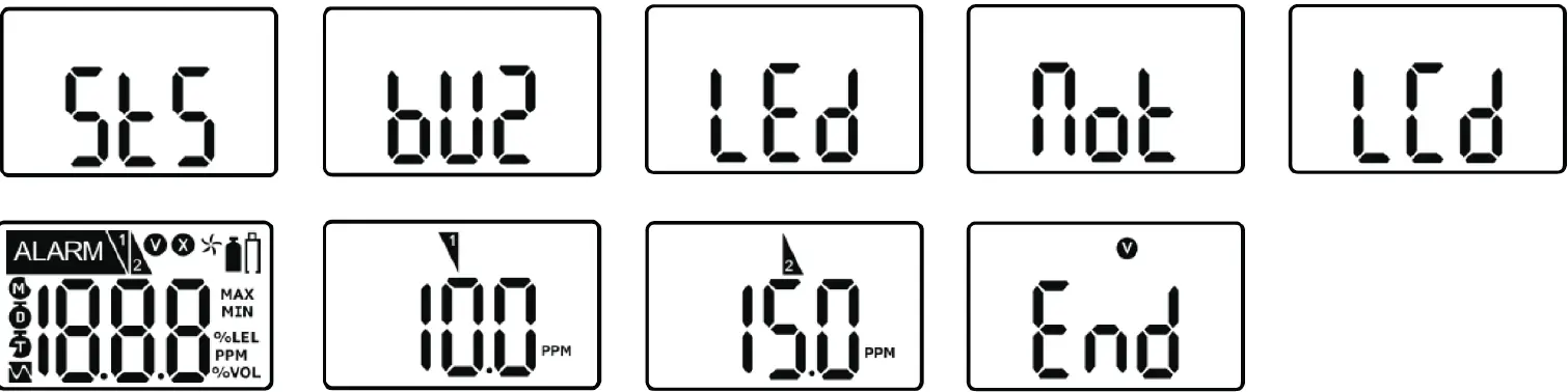
SELF TEST
The default interval of the Self-Test is 20hr, meaning the PDM+ will ask for a self test after each 20 hours of use. By default the Self-Test setting is turned off.
The interval is configurable via IR-Link between 8~20 hours. The self test can also be switched off via IR-Link.
When the interval is activated, STS message will flash. The message will flash until users perform the Self test.
Once you press the button, it will test buzzer, LED, Vibration, LCD, and show alarm thresholds. After the test is completed, END message with V icon will be displayed. (Users are required to check the test processes.)
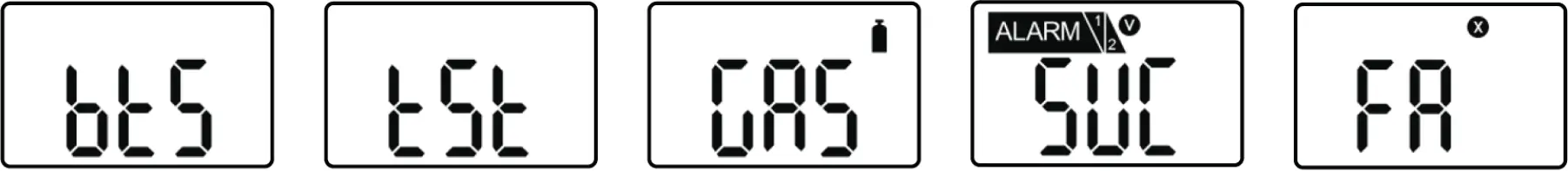
BUMP TEST
The interval of Bump test is 1~365days, and the default is switched off. To initiate the bump test, set the bump test interval. Once the bump test interval expires, Bts message will flash.
Put the PDM+ in the docking station with a valid and full gas cylinder. Alternatively, attach the calibration adapter to PDM+ and a valid and full gas cylinder. Press and hold the key for 3 seconds, the TST message will be displayed for 45 seconds (To cancel, press the button for one second). Within the 45 seconds, start the flow from the gas cylinder. If no gas is applied, the bts message will flash again.
If the test is successful, SUC message with will V be displayed for 30 seconds. Stop the flow, remove the calibration adapter. If the test fails, FA message with , X will be displayed and BTS message will be flashing until the test is successful. If the bump test repeatedly fails, contact WatchGas.
Sensor & Battery Replacement
Caution
It is absolutely prohibited to replace battery at potential explosion or dangerous regions. Replace the battery in a clean environment, which has no hazardous gases. Replacement of components can invalidate the intrinsic safety function.
Replacing the sensor and battery should be performed by authorized sellers, agents, distributors, or managers. Contact WatchGas if replacement is needed.
Disassembly should be necessary only for sensors & battery replacement. After the sensor replacement, Fresh air and SPAN calibration should be done. Before disassembling, please turn off the power and remove screws.
Only use SB-AA02 3.6V battery.
SENSOR REPLACEMENT
- Deactivate the detector
- Remove the 6 screws on the back case and carefully open the case.
- Remove the 2 screws on the PCB board.
- After removing the battery, replace with the new sensor matching with the gas type. For instance, If you have the PDM+ CO, the CO sensor should be used for the replacement.
- Assemble the detector.
- Have the sensor stabilized for 5 minutes before use.
- After assembling, perform the fresh air calibration and standard calibration with the concentration in this manual.
- Check the settings.
BATTERY REPLACEMENT
- Deactivate the detector
- Remove the 6 screws on the back case.
- Replace battery with original SB-AA02 3.6V battery only
- Assemble the detector.
- After assembling, perform the fresh and standard calibration.
- Before use, have the sensor stabilized for 5 minutes. Some sensor may require al longer stabilization time.
Specifications
GENERAL SPECIFICATIONS
| Size | 48mm(W) x 85mm(H) x 22mm(D) |
| Weight | 93g (Toxic), 104g (O2) (Battery, clip included) |
| Sensor technology | Electrochemical Cell |
| Temperature | -40ºC ~ +50ºC (for Toxic) / -35ºC ~ +50ºC (for O2) |
| Humidity | 5% ~ 95% RH (Non-condensing) |
| Alarm type | High Alarm, Low Alarm, TWA Alarm, STEL Alarm, Over range Alarm, Battery low alarm, Bumptest and calibration due notification |
| Alarm signal | Acoustic: 95dB @ 30cm Visual: Red flashing LED’s Vibration: Vibration |
| Display | LCD Display |
| Calibration | 2-point calibration, zero and span |
| Event log | 30 Most recent events |
| Battery | Lithium Primary Battery SB-AA02(P) 3.6V, 1.2Ah |
| Measurement | Diffusion |
| Housing | Polycarbonate and rubber |
| Accuracy deviation | 2-3% |
| IP-Rating | IP67 |
| Safety certifications | ATEX: II 1G Ex ia IIC T4 Ga INMETRO: Ex ia IIC T4 Ga IECEx: Ex ia IIC T4 Ga CE: Conformité Européenne |
| Warranty | 24 Months O₂, CO, H₂S, H2,SO₂, NH3, and NO₂ 12 months for H₂O₂ |
SENSOR SPECIFICATIONS
| Model | Detectable Gas Ranges | Resolution | Article Numbers |
| PDM+ O₂ | 0 – 30 %vol | 0.1 %vol | 7192002 |
| PDM+ CO | 0 – 500 ppm | 1 ppm | 7192001 |
| PDM+ CO High Range | 0-2000 ppm | 1 ppm | 7192009 |
| PDM+ H₂S | 0 – 100 ppm | 0.1 ppm | 7192000 |
| PDM+ H2 | 0 – 1000 ppm | 1 ppm | 7192005 |
| PDM+ SO₂ | 0 – 50 ppm | 0.1ppm | 7192004 |
| PDM+ NH3 | 0 – 100 ppm | 1 ppm | 7192003 |
| PDM+ H₂O₂ NON-ATEX | 0 – 99 ppm | 0.1 ppm | 7192007 |
| PDM+ NO2 | 0 – 20 ppm | 0.1 ppm | 7192011 |
IR Link Settings
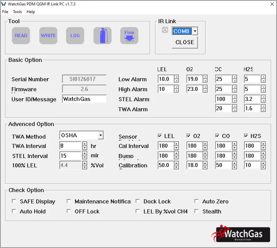
Users can change settings, upgrade firmware, download log events, and perform calibration with the WatchGas IR Link.
Getting Started
To interact with WatchGas QGM or PDM, ensure to install the software and have the link cable plugged into the computer. And, place the topside of WatchGas QGM or PDM to the IR Link LCD.
File
- Load: Open the installed settings. (*cfg)
- Save: Save the current settings. (*cfg)
- Exit: Close the program.
Tools
- Calibration: Perform the zero/span calibration.
- Log Read: Retrieve the log events.
- Log Erase: Erase the log events.
- Self Test: Test if LED, LCD, Buzzer, vibration, battery and temperature works properly.
- FW Upgrade Users can upgrade firmware.
- The up- to-date firmware is available at our WatchGas website
- Factory Fault: Remove all data and restore the initial factory settings.
Help
About: Display a brief company profile.
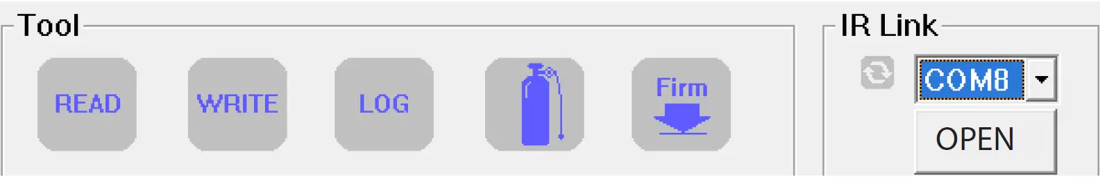
Tool
- READ: Retrieve the settings.
- WRITE: Update the adjusted settings. LOG: Display the saved log events.
- CALIBRATION: Perform the zero and span calibration.
- FIRMWARE UPGRADE: Upgrade firmware.
IR Link
- OPEN: In order to interact the IR Link with QGM and PDM click on ‘OPEN’. When the read is activated successfully. Users will see “Read Complete”.
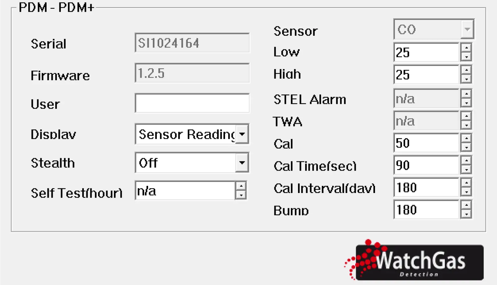
PDM and PDM+
- SERIAL NUMBER: Display a preset serial number.
- FIRMWARE VERSION: Display a firmware version (EX. 1.x.x) .
- USER ID/MESSAGE: Users can program a desired message/ID.
- DISPLAY: Users can choose to display either the real time “Sensor Reading” or “Sensor Life remaining”.
- STEALTH (OPTION): Users can turn off the buzzer, LED, and vibration.
- SELF TEST (HOUR): Set an interval of the self-test alert.
- SENSOR TYPE: Display a sensor type of the device.
- LOW ALARM: Adjust the low alarm set point in compliance with international or local standards.
- HIGH ALARM: Adjust the high alarm set point in compliance with the international or local standards.
- CAL CONCENTRATION: Set a standard calibration value.
- CAL TIME (SEC): Set a standard calibration time.
- CAL INTERVAL (DAY) Set an interval of the calibration alert.
- BUMP INTERVAL (DAY) Set an interval of the bump test alert.
- STEL ALARM: Adjust the STEL alarm set point in compliance with international or local standards.
- TWA: Adjust the TWA alarm set point in compliance with international or local standard
Limited Warranty
WATCHGAS warrants this product to be free of defects in workmanship and materials-under normal use and service-for two years from the date of purchase from the manufacturer or from the product’s authorized reseller.
The manufacturer is not liable (under this warranty) if its testing and examination disclose that the alleged defect in the product does not exist or was caused by the purchaser’s (or any third party’s) misuse, neglect, or improper installation, testing, or calibrations. Any unauthorized attempt to repair or modify the product, or any other cause of damage beyond the range of the intended use, including damage by fire, lightening, water damage or other hazard, voids liability of the manufacturer.
In the event that a product should fail to perform up to manufacturer specifications during the applicable warranty period, please contact the product’s authorized reseller or WATCHGAS service center at +31 (0)85 01 87 709 for repair/return information.
WatchGas B.V.
Klaverbaan 121
2908 KD Capelle aan den IJssel
+31 (0)85 01 87 709
The Netherlands
[email protected] – www.watchgas.com


