WatchGas UNI Sustainable Single Gas Detector
Description
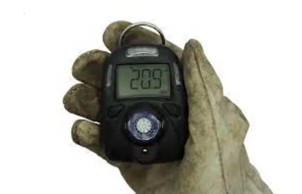
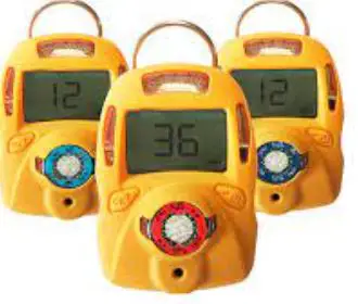
The UNI Sustainable is a single sensor, portable, personal toxic gas monitor. It displays gas concentration continuously on a big segment LCD. It also monitors STEL, TWA, peak and min (for O2 only) value of the gas and can be displayed on demand. High, Low, STEL&TWA alarm threshold values are configurable. The shell is made of high strength, durable material. Two key operation, simple to use. Sensor and battery can be replaced easily. Calibration is also very convenient.
Warning
This manual must be carefully read by all individuals who have or will have the responsibility of using, maintaining or servicing this product. The product will perform as designed only if it is used, maintained and serviced in accordance with the manufacturer’s instructions.
• Never operate the monitor when the cover is removed.
• Remove the monitor cover and battery only in area known as non-hazardous.
• Use only WatchGas lithium battery.
• This instrument has not been tested in an explosive gas/air atmosphere having an oxygen concentration greater than 21%.
• Substitution of components will impair suitability for intrinsic safety.
• Substitution of components will void warranty.
• It is recommended to bump test with a known concentration gas to confirm the instrument is functioning properly before use.
• Before use, ensure that the ESD film on the display is not damaged or peeling.
Proper Disposal
The Waste Electrical and Electronic Equipment(WEEE) directive (2012/19/EU) is intended to promote recycling of electrical and electronic equipment and their components at end of life . This symbol (crossed-out wheeled bin) indicates separate collection of waste electrical and electronic equipment in the EU countries. This product may contain one or more Nickel-metal hydride (NiMH), Lithium-ion, or Alkaline batteries. Specific battery information is given in this user guide. Batteries must be recycled or disposed of properly. At the end of its life, this product must undergo separate collection and recycling from general or household waste. Please use the return and collection system available in your country for the disposal of this product.
Product Overview
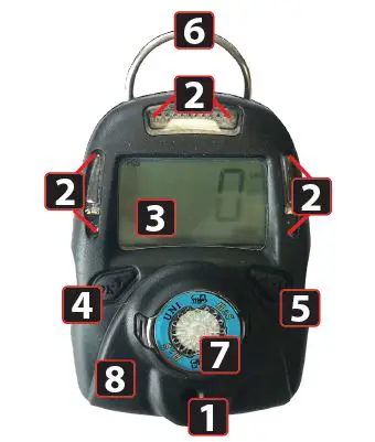
DETECTOR COMPONENTS
1. Audible Alarm Port
2. LED alarm window
3. LCD
4. Left Key (Confirm/Number increasing)
5. Right Key (Power/ Cursor moving)
6. Alligator clip
7. Sensor
8. Vibrator
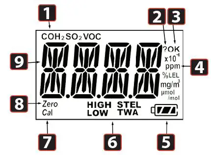
DISPLAY SYMBOLS
1. Gas name, includes: CO, H2S, SO2, O2, VOC
2. Question mark
3. OK
4. Gas unit, includes: x10-6, ppm, %, mg/m3, μmol/mol
5. Battery
6. HIGH, LOW, STEL, TWA alarm
7. Span calibration
8. Zero calibration
9. Number
Activation
SWITCH ON
Press and hold the Right Key for 3 seconds, until LCD displays ( ) , buzzer beeps, green LED flashes, then release the button, the unit is powered on.
WARM-UP SEQUENCE
After powered on, the unit enters a warm up and self-test sequence and shows the firmware version as follows:
If the sensor is not able to be identified by the instrument or is not installed into the instrument, then the screen switches between and .Otherwise, the following values will be shown accordingly:
- High alarm threshold value
- Low alarm threshold value
- STEL (short-term exposure limit) alarm threshold value
- TWA (time-weighted average) alarm threshold value
Mode
NORMAL MODE
The unit enters normal mode, start monitoring gas concentration and display on the LCD screen.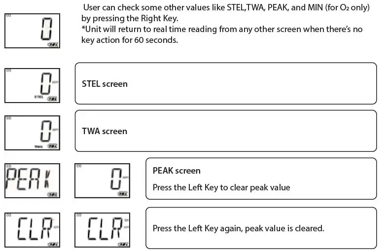
MIN SCREEN (FOR OXYGEN SENSOR ONLY)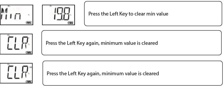
TURN UNIT OFF
In normal display mode, press and hold the Right Key, then the unit will display a 5 second count down, LEDs will flash and buzzer will beep once per second.
CONFIG MODE
In Config mode, user can do calibration & change parameters for the unit. In general, use the Left Key to increase the number or confirm, use the Right Key to move the cursor or move to the next programming item.
ENTER CONFIG MODE
Press and hold the Left Key and the Right Key together for 3 seconds, the unit enters Config mode. The Config mode is password protected, LCD displays to prompt enter password. The screen displays , with one digit flashing. To input password, use the Left Key to increase the number, use the Right Key to move cursor. Once all four digits are input, the cursor will move to “OK”, use the Left Key to finish password input and enter the Config mode. If the digit input is mistaken, use the Right Key to move cursor between four digits and “OK” mark, to change the input. *WatchGas Sustainable preset password is 0000.
SENSOR CALIBRATION
Before the unit can monitor gas correctly, it needs to know the metric, this is done by zero calibration and span calibration.
CALIBRATION ADAPTER
1. Calibration adapter is used to apply gas to the unit during calibration.
2. Before span calibration (in the following section), attach the Calibration Adapter over the inlet port on the front of the UNI Sustainable by pressing it into place.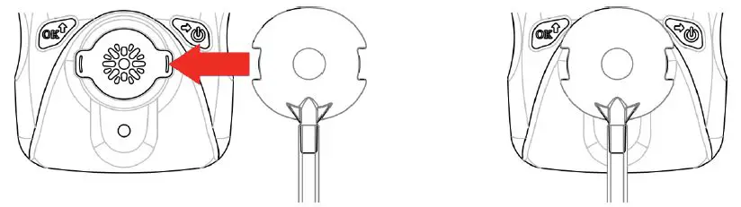
3. Open the gas cylinder valve, then press the Left Key to start the calibration count down.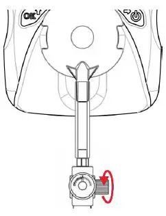
4. Take off the Calibration Adapter and complete calibration.
When monitoring, never operate the UNI Sustainable with the Calibration Adaptor attached. The UNI Sustainable’s sensor operates by diffusion. If the Calibration Adapter is attached during normal operation, inconsistent and lower-than-normal readings will occur because of decreased concentration of the gas being monitored.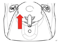
ZERO CALIBRATION
Zero calibration is to set the base line for the sensor, it is done in fresh air. When LCD displays press the Left Key to start zero calibration. The unit will start a 15 second count-down, after the countdown is finished, zero calibration result will be displayed on the LCD, pass or fail . If user does not want to do zero calibration, during the 15 seconds count, press the Right Key, , zero calibration is aborted.
SPAN CALIBRATION
Span calibration is to set the metric of the sensor to the gas, it is done with a known concentration gas. When LCD displays apply the known gas to the unit, then press the Left Key to start span calibration. Unit will start count-down, the count-down time depends on different sensors (normally 60 seconds), after count-down is finished, span calibration result will pass or fail . If user does not want to do span calibration during count-down, press the Right Key, LCD displays , span calibration is aborted.
BUMP TEST
Bump test is to check if sensor and alarm devices are working properly, it is done with a known concentration gas. When LCD displays , apply the known gas to the unit, then press the Left Key to start bump test. Unit will start count-down, the count-down time depends on different sensors (normally 45 seconds), after count-down is finished, bump test result will be displayed on the LCD, pass or fail. If user does not want to do bump test during count-down, press the Right Key, LCD displays , bump test is aborted.
CHANGE ALARM LIMIT
All the preset alarm limits, High, Low, STEL & TWA can be changed. When LCD displays: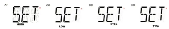
Press the Left Key, to change the corresponding alarm limit, the value change process is similar. First the current setting value is displayed, with the first digit flashing: . Use the Left Key to increase the current digit, , cycle from 0 to 9. Use the Right Key to move cursor to the next digit:
After all digits are done, use the Right Key to move cursor to “OK” symbol, press the Left Key to confirm the changing.
- The UNI Sustainable will show “Err”, if the input data is invalid as follows,
- Low alarm setting is bigger than high alarm setting.
- High alarm setting is smaller than low alarm setting.
- Input data is bigger than measuring range.
CHANGE BUMP/CAL INTERVAL
The bump and cal interval can also be changed. When LCD switches between:
Press the Left Key, to change the corresponding interval range, the value change process is similar. First the current setting value is displayed, with the first digit flashing: . Use the Left Key to increase the current digit, , cycle from 0 to 9. Use the Right Key to move cursor to the next digit: After all digits are done, use the Right Key to move cursor to “OK” symbol, press the Left Key to confirm the changing. The UNI Sustainable will show “Err”, if the input data is out of valid range: 0~180 day(s).
CHANGE SPAN VALUE
The span calibration preset value can also be changed, the change process is similar with the alarm limit. But the new span will not take effect until user successfully completes a span calibration next time.
- UNI Sustainable will show “Err”, if the input data is invalid as follows:
- Span setting is smaller than 5% measuring range or bigger than measuring range.
- For Oxygen sensor, span setting is bigger than 19.0.
CHANGE DISPLAY UNIT
The UNI Sustainable supports different gas units, to change gas unit, when LCD switches between and , press the Left Key to change gas unit. The supported units for current sensor are all displayed on the LCD, the current selected unit is blinking. Use the Right Key to change unit, use the Left Key to confirm selected gas unit.
VIBRATOR ENABLE/DISABLE
The vibrator consumes a lot of power, it can be disabled to save battery power, to extend the battery life. When LCD switches between and , press the Left Key to change the vibrator enable/ disable status. The current vibrator status is displayed on the LCD, switching between and if the vibrator is enabled, or switching between and , if the vibrator is disabled. Use the Right Key to change the enable/disable status, and use the Left Key to confirm the change.
POWER ON ZERO ENABLE/DISABLE
Sensor base line may have some changes due to the environment (temperature, humidity), that will require a zero calibration. Mthe Uni Sustainable can do zero calibration every time the unit is poweredon; this feature can be enabled/disabled. When LCD switches between and , press the Left Key to go to change power on zero calibrations enable/disable status. The current enable/disable status is displayed on the LCD, use the Right Key to change, use the Left Key to confirm the change.
FAST POWER ON ENABLE/DISABLE
If fast startup is enabled, the screens showing High/Low/STEL/TWA alarm threshold value will be skipped during warm up sequence. When LCD switches between and , press the Left Key to change fast startup enable/disable status. The status is displayed on the LCD, switching between and if the fast startup is enabled, or switching between and if the fast startup is disabled. Use the Right Key to change the enable/disable status, use the Left Key to confirm the change.
RESET CONFIG
If the unit parameter is incorrect and user does not know how to set them back, user can use reset config to make all the parameters back to factory default. When LCD switches between and , press the Left Key to enter config reset menu, press the Left Key to confirm config reset.
EXIT CONFIG
When LCD displays EXIT , press the Left Key exit from Config mode back to normal mode.
Maintenance
Caution: Maintenance should be performed only by a qualified person who has proper training and fully understands the contents of the manual.
REPLACE THE BATTERY
When the battery’s charge is low, LCD displays , battery low alarm will be triggered once every minute. User needs to replace the battery. When battery is dead, LCD displays , battery dead alarm will be triggered once every second. User needs to replace the battery.
To replace battery:
- Turn off the UNI Sustainable.
- Place the UNI Sustainable face down on a soft surface.
- Use a T10 Torx screwdriver to loosen each of the four screws by turning them counterclockwise.
- Remove the top cover after carefully unplugging the buzzer connector.
- Slide the battery out of its compartment.
- Place the new battery into the compartment with its “+” end oriented toward the “+” on the printed circuit board.
- Plug in the buzzer connector and reinstall the top cover.
- Install the screws in back cover. Be careful to not overtighten the screws.
REPLACE THE SENSOR FILTER
A “peel-and-stick” filter should be used on the UNI Sustainable in order to keep debris from fouling the sensor. Sheets of 5 filters are available. When the filter appears dirty, replace it with a new one and dispose of the dirty filter.
- Turn off the UNI Sustainable.
- Place the UNI Sustainable face down on a soft surface.
- Use a T10 Torx screwdriver to loosen each of the four screws by turning them counterclockwise.
- Remove the top cover after carefully unplugging the buzzer connector.
- Peel a filter from the sheet and center it over the sensor. Gently press down.
- Plug in the buzzer connector and reinstall the top cover.
- Install the screws in back cover. Be careful to not overtighten the screws.
REPLACE THE SENSOR
The UNI Sustainable models are designed so that you can easily change the sensor.
- Turn off the unit.
- Place the UNI Sustainable face down on a soft surface.
- Use a T10 Torx screwdriver to loosen each of the four screws by turning them counterclockwise.
- Remove the top cover after carefully unplugging the buzzer connector.
- Replace the old sensor with a new one. Make sure the pins are not bent or corroded . Align the pins to the corresponding holes and push the sensor straight in . The sensor should fit flush against the printed circuit board.
- Plug in the buzzer connector and reinstall the top cover.
- Install the screws in back cover. Be careful to not overtighten the screws.
Warning: Sensors are not interchangeable. Use only WatchGas sensors, and use only the sensor type specified for your UNI Sustainable monitor. Use of non-WatchGas components will void the warranty and can compromise the safe performance of this product.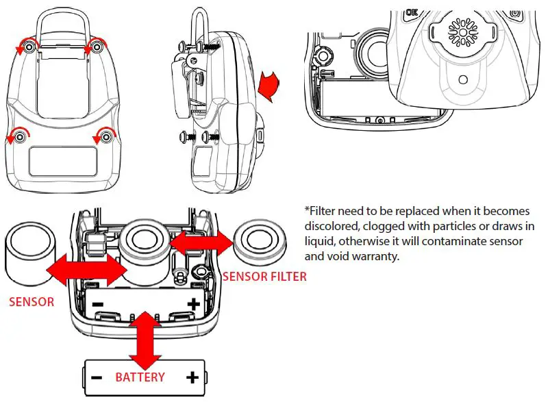
Caution: Change battery only in area known to be non-hazardous. Use only WatchGas battery.
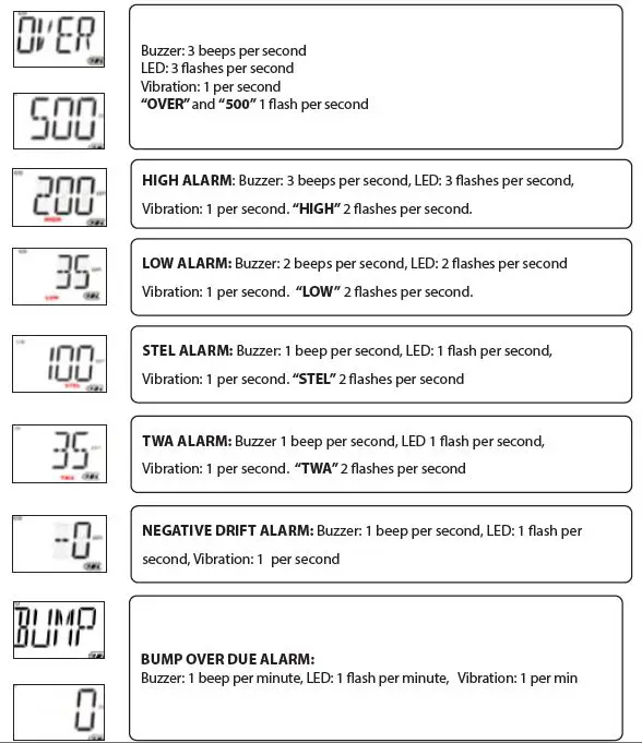
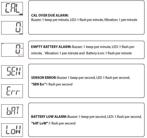
Alarm signal summary

Trouble shooting
| Problem | Possible reason | Solution |
| Can not turn on unit | Battery not installed | Install battery |
| Depleted or defective battery | Replace battery | |
| Reading abnormally low | Calibration Adapter is attached. | Remove Calibration Adapter |
| Incorrect calibration. | Calibrate the UNI Sustainable | |
| Buzzer, LED, or vibration alarm inoperative | Bad buzzer, LEDs, or vibration alarm. | Call authorized service center |
| Blocked alarm port | Unblock alarm port |
Specifications
DETECTOR SPECIFICATIONS
| Size | 88 (W)x 62 (H) x 33 (D) mm (3.66 x 2.44 x 1.3 in) |
| Weight | 125 g (4.4 oz) |
| Sensor technology | 34 electrochemical sensor options |
| Temperature | -20°C to 50°C ( -4 to 122°F) |
| Humidity | 5% ~ 95% RH (Non-condensing) |
| Alarm type | High alarm, Low alarm, STEL alarm, TWA alarm, adjustable. Over range alarm, Battery low alarm, Bumptest and calibration due notification |
| Alarm signal | Acoustic: 95dB @ 30cm Visual: 6 bright red LEDs Vibration alarm |
| Display | LCD Display |
| Calibration | 2-point calibration, zero and span. Power-on zero calibration with user confirmation. |
| Event log | Up to 50 alarm events |
| Battery | Replaceable 3.6V AA Lithium battery for 3 years of operation |
| Measurement | Diffusion |
| Housing | Polycarbonate and rubber |
| Response time t90 | 15 sec (CO/H2S/O2) Others gases vary (technical note 4: Sensor Technical Data Summaries) |
| Accuracy deviation | 2-3% |
| IP-Rating | IP68 |
| EMI/RFI | Compliant with EMC 2014/30/EU |
| Safety certifications | UL: Class I, Div 1, Group A, B, C, D Class II, Div 1, Group E, F, G Class III, Div 1 T4, -20° C ≤ Tamb ≤ +50° C ATEX: II 1G Ex ia IIC T4 Ga IECEX: Ex ia IIC T4 Ga CE: Conformité Européenne |
| Sensor Life | CO/H2S: 5 years Other sensors: 1 to 2 years as per warranty |
| Warranty | 2 years for UNI Sustainable with O2, H2S, CO, SO2, HCN, NO, NO2or PH3 sensor |
| 1 year for UNI Sustainable with other sensors |
SENSOR SPECIFICATIONS
| Model | Detectable Gas Ranges | Resolution | Article Number | ||
| CO Carbon Monoxide | 0 – 500 ppm 0 – 1000 ppm 0 – 2000 ppm | 915 mg/m3 1829 mg/m³ 3658 mg/m3 | 1 ppm 1 ppm 1 ppm | 2 mg/m3 2 mg/m3 2 mg/m3 | M001-0002-W00 M001-0023-W00 M001-0026-W00 |
| H2S Hydrogen Sulfide | 0 – 50 ppm 0 – 100 ppm 0 – 200 ppm 0 – 1000 ppm | 71 mg/m3 142 mg/m3 284 mg/m3 1418 mg/m3 | 0.1 ppm 0.1 ppm 0.1 ppm 1 ppm | 0.1 mg/m3 0.1 mg/m3 0.1 mg/m3 1 mg/m3 | M001-0003-W00 M001-0054-W00 M001-0057-W00 M001-0060-W00 |
| O2 Oxygen | 0 – 25 %vol 0 – 30 %vol | 0.1 %vol 0.1 %vol | M001-0032-W00 M001-0001-W00 | ||
| O2 Lead-free Oxygen | 0 – 25 %vol 0 – 30 %vol | 0.1 %vol 0.1 %vol | M001-0094-W00 M001-0095-W00 | ||
| O2 Inerting Alarms Oxygen | 0 – 25 %vol | 0.1 %vol | M001-0093-W00 | ||
| SO2 Sulfur Dioxide | 0 – 20 ppm 0 – 100 ppm | 53 mg/m3 266 mg/m3 | 0.1 ppm 0.1 ppm | 0.3 mg/m3 0.3 mg/m3 | M001-0007-W00 M001-0091-W00 |
| Cl2 Chlorine | 0 – 50 ppm | 147 mg/m3 | 0.1 ppm | 0.3 mg/m3 | M001-0004-W00 |
| NO Nitric Oxide | 0 – 250 ppm | 312 mg/m3 | 1 ppm | 1 mg/m3 | M001-0015-W00 |
| NO2 Nitrogen Dioxide | 0 – 20 ppm | 38 mg/m3 | 0.1 ppm | 0.2 mg/m3 | M001-0011-W00 |
| H2 Hydrogen | 0 – 1000 ppm 0 – 2000 ppm | 83 mg/m3 166 mg/m3 | 1 ppm 1 ppm | 0.1 mg/m3 0.1 mg/m3 | M001-0018-W00 M001-0019-W00 |
| PH3 Phosphine | 0 – 20 ppm | 28 mg/m3 | 0.01 ppm | 0.01 mg/m3 | M001-0016-W00 |
| ETO Ethylene Oxide | 0 – 100 ppm 0 – 200 ppm | 183 mg/m3 367 mg/m3 | 0.1 ppm 0.1 ppm | 0.2 mg/m3 0.2 mg/m3 | M001-0012-W00 M001-0069-W00 |
| NH3 Ammonia | 0 – 100 ppm 0 – 500 ppm | 71 mg/m3 353 mg/m3 | 1 ppm 1 ppm | 1 mg/m3 1 mg/m3 | M001-0006-W00 M001-0090-W00 |
| ClO2 Chlorine Dioxide | 0 – 1 ppm | 3 mg/m3 | 0.01 ppm | 0.03 mg/m3 | M001-0072-W00 |
| O3 Ozone | 0 – 5 ppm | 10 mg/m3 | 0.01 ppm | 0.02 mg/m3 | M001-0009-W00 |
| HF Hydrogen Fluoride | 0 – 20 ppm | 17 mg/m3 | 0.1 ppm | 0.1 mg/m3 | M001-0014-W00 |
| HCl Hydrogen Chloride | 0 – 15 ppm | 23 mg/m3 | 0.1 ppm | 0.2 mg/m3 | M001-0008-W00 |
| HCN Hydrogen Cyanide | 0 – 100 ppm | 112 mg/m3 | 0.1 ppm | 1 mg/m3 | M001-0005-W00 |
| CH3SH Methyl Mercaptan | 0 – 10 ppm | 20 mg/m3 | 0.1 ppm | 0.2 mg/m3 | M001-0077-W00 |
| THT Tetrahydrothiophene | 0 – 40 ppm | 144 mg/m3 | 0.1 ppm | 0.4 mg/m3 | M001-0085-W00 |
| C2H4O Acetaldehyde | 0 – 20 ppm | 37 mg/m3 | 0.1 ppm | 0.2 mg/m3 | M001-0080-W00 |
| AsH3 Arsine | 0 – 1ppm | 3.24 mg/m3 | 0.01 ppm | 0.03 mg/m3 | M001-0092-W00 |
| COCl2 Phosgene | 0 – 1ppm | 4.11 mg/m3 | 0.01 ppm | 0.04 mg/m3 | M001-0020-W00 |
Limited Warranty
WATCHGAS warrants this product to be free of defects in workmanship and materials under normal use and service for two years from the date of purchase from the manufacturer or from the product’s authorized reseller. The manufacturer is not liable (under this warranty) if its testing and examination disclose that the alleged defect in the product does not exist or was caused by the purchaser’s (or any third party’s) misuse, neglect, or improper installation, testing, or calibrations. Any unauthorized attempt to repair or modify the product, or any other cause of damage beyond the range of the intended use, including damage by fire, lightening, water damage or other hazard, voids liability of the manufacturer. In the event that a product should fail to perform up to manufacturer specifications during the applicable warranty period, please contact the product’s authorized reseller or WATCHGAS service center at +31 (0)85 01 87 709 for repair/return information.
All rights reserved. No part of this publication may be reproduced, distributed, or transmitted in any form or by any means, including photocopying, recording, or other electronic or mechanical methods, without the prior written permission of the publisher, except in the case of brief quotations embodied in critical reviews and certain other noncommercial uses permitted by copyright law. For permission requests, contact WatchGas B.V.
WatchGas B.V.
Klaverbaan 121
2908 KD Capelle aan den IJssel
+31 (0)85 01 87 709
The Netherlands
[email protected] – www.watchgas.eu


