Anybus AWB2030 Wireless Bolt RJ45 PoE User Guide
Preparation
About This Document
This document describes how to install Anybus Wireless Bolt RJ45 PoE and set up a basic configuration.
For additional documentation, configuration examples, FAQs, troubleshooting guides and technical support, please visit www.anybus.com/support.
Document Conventions
The following conventions are used to indicate safety information and other important content in this document:
![]() WARNING Instruction that must be followed to avoid a risk of death or serious injury.
WARNING Instruction that must be followed to avoid a risk of death or serious injury.
![]() Caution
Caution
Instruction that must be followed to avoid a risk of personal injury.
![]() Instruction that must be followed to avoid a risk of reduced functionality and/or damage to the equipment, or to avoid a network security risk.
Instruction that must be followed to avoid a risk of reduced functionality and/or damage to the equipment, or to avoid a network security risk.
![]() Additional information which may facilitate installation and/or operation.
Additional information which may facilitate installation and/or operation.
Trademarks
Anybus® is a registered trademark and Wireless Bolt™ is a trademark of HMS Industrial Networks AB. All other trademarks mentioned in this document are the property of their respective holders.
Intended Use
This equipment is intended to provide wireless communication over WLAN and Bluetooth® to wired networks.
Typical applications for this equipment:
- Adding wireless cloud connectivity to industrial devices
- Accessing devices from a laptop, smartphone or tablet
- Ethernet cable replacement between devices
Note:
Bluetooth PAN (Personal Area Network) may not work with some devices due to different implementations of Bluetooth by different manufacturers.
WLAN 5 GHz cannot be used at the same time as WLAN 2.4 GHz or Bluetooth.
Type Identification
The type name consists of a type prefix followed by two designators for interface configuration and functionality.
| Prefix | AWB2 | Anybus Wireless Bolt |
| Interface configuration |
|
|
| Functionality |
|
|
Example: AWB2AA = Anybus Wireless Bolt with18-pin plug connector and Ethernet networking only.
Installation
General Safety Instructions
![]() Caution
Caution
This equipment emits RF energy in the ISM (Industrial, Scientific, Medical) band. Make sure that all medical devices used in proximity to this equipment meet appropriate susceptibility specifications for this type of RF energy.
![]() This equipment is recommended for use in both industrial and domestic environments. For industrial environments it is mandatory to use the functional earth connection to comply with immunity requirements. For domestic environments the functional earth must be used if a shielded Ethernet cable is used, in order to meet emission requirements.
This equipment is recommended for use in both industrial and domestic environments. For industrial environments it is mandatory to use the functional earth connection to comply with immunity requirements. For domestic environments the functional earth must be used if a shielded Ethernet cable is used, in order to meet emission requirements.
![]() This equipment contains parts that can be damaged by electrostatic discharge (ESD). Use ESD prevention measures to avoid damage.
This equipment contains parts that can be damaged by electrostatic discharge (ESD). Use ESD prevention measures to avoid damage.
General Information
Make sure that you have all the necessary information about the capabilities and restrictions of your local network environment before installation.
For optimal reception, wireless devices require a zone between them clear of objects that could otherwise obstruct or reflect the signal. A minimum distance of 50 cm between the devices should also be observed to avoid interference.
The characteristics of the antenna should also be considered when choosing the placement and orientation of the unit.
See the Anybus Wireless Bolt RJ45 PoE User Manual for more information.
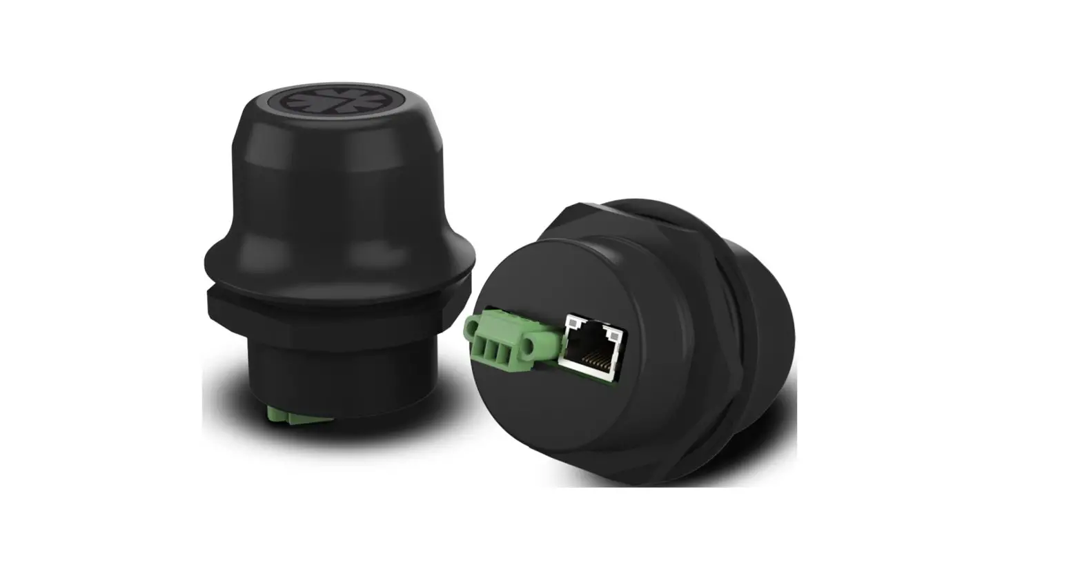
Mechanical Installation
Placement
- The device is intended to be mounted on top of a machine or cabinet through an M50 (50.5 mm) hole using the included sealing ring and nut.
- The top mounting surface, in contact with the sealing, must be flat with a finish equivalent to Ra 3.2 or finer and cleaned and free from oils and greases.
- For optimal reception, wireless devices require a zone between them clear of objects that could otherwise obstruct or reflect the signal. To avoid interference, a minimum distance of 50 cm between Wireless Bolt RJ45 PoE and other devices should be observed.
![]() Make sure that the sealing ring is correctly placed in the circular groove in the top part of the housing before tightening the nut.
Make sure that the sealing ring is correctly placed in the circular groove in the top part of the housing before tightening the nut.
![]() Always hold the BOTTOM part of the unit when untightening the nut, not the top part (the cap).
Always hold the BOTTOM part of the unit when untightening the nut, not the top part (the cap).
Tightening torque: 5 Nm ±10 %
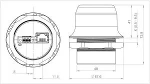
All measurements are in mm.
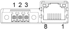
Connectors
![]() Connecting power with reverse polarity or using the wrong type of power supply may damage the equipment. Make sure that the power supply is connected correctly and of the recommended type.
Connecting power with reverse polarity or using the wrong type of power supply may damage the equipment. Make sure that the power supply is connected correctly and of the recommended type.
See also Technical Data, p. 14 regarding power supply requirements.
Power Connector (3-pin terminal block) | ||
Pin | Function | |
1 | + | 19–36 VDC |
2 | – | |
| 3 | Functional Earth (FE) | |
FE must be connected on the power connector if not using PoE.
Ethernet Connector (RJ45 PoE) | |||
Pin | Data | PoE | |
1 | TD+ | A+ | Positive power from alt. A PSE |
2 | TD- | A+ | |
3 | RD+ | A- | Negative power from alt. A PSE (with pin 6) |
4 | B+ | Positive power from alt. B PSE | |
5 | B+ | ||
| 6 | RD- | A- | Negative power from alt. A PSE (with pin 3) |
7 | B- | Negative power from alt. B PSE | |
8 | B- | ||
Housing | Shield | Functional Earth (FE) via 1 nF capacitor and 1 MΩ bleeder resistor | |
Shielded or unshielded Ethernet cables may be used.
RJ45 LED Indicators
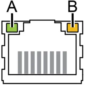
| LED A – LINK/ACTIVITY | Function |
| Off | No Ethernet link or no power |
| Yellow | Ethernet link established |
| Yellow, flashing | Ethernet traffic |
| LED B – STATUS | Function |
| Off | No power |
| Blue | Connected on all configured wireless interfaces |
| Purple | Trying to connect to WLAN/Bluetooth access point |
| Blue, slow blink | Awaiting connections |
| Alternating blue/purple | Connected on one interface and trying to connect or awaiting connections on another |
| Purple, slow blink | Awaiting connections on one interface and trying to connect on another |
| Purple, fast blink | Scanning for Bluetooth devices or WLAN networks |
| Red, slow blink | No configured wireless interface |
| Red | Recoverable/unrecoverable fault |
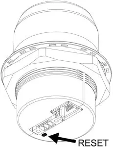
The RESET button is located on the bottom of the unit.
When the unit is powered on, press and hold RESET for >10 seconds and then release it to reset to the factory default settings.
Recovery Mode
If the web interface cannot be accessed, the unit can be reset by starting in Recovery Mode and reinstalling the firmware using Anybus Firmware Manager II, which can be downloaded from www.anybus.com/support.
To enter Recovery Mode, press and hold RESET during startup.
![]() Firmware updates should normally be carried out through the web interface. Recovery Mode should only be used if the unit is unresponsive and the web interface cannot be accessed.
Firmware updates should normally be carried out through the web interface. Recovery Mode should only be used if the unit is unresponsive and the web interface cannot be accessed.
Configuration
Anybus Wireless Bolt RJ45 PoE is configured via a web interface. Parameters can be set individually or using pre-configured Easy Config modes.
Advanced configuration can be carried out by issuing AT commands via the web interface or over a Telnet or RAW TCP connection to port 8080.
Web Interface
The web interface is accessed by pointing a web browser to the IP address of the unit. The default address is 192.168.0.99.
The configuration settings are described in detail in the User Manual.

Easy Config Modes
By default Wireless Bolt RJ45 PoE starts in Easy Config mode 4, when:
- the Ethernet connection is not used
- connected to power
- factory default settings are used
EC | Role | Description |
1 | Bluetooth PANU | Configure as Bluetooth client and scan for another client (PANU to PANU). |
2 | – | Reset configuration to factory defaults. |
3 | – | Reset IP settings to factory defaults. |
4 | Client |
|
5 | WLAN AP | Configure units in mode 4 as clients. Restart as access point and connect clients. |
6 | Bluetooth NAP | |
7 | WLAN AP |
|
8 | Bluetooth NAP | |
9 | Bluetooth PANU |
|
10 | (any) | Apply PROFINET optimization and restart. |
11 | (any) | Enable PROFIsafe mode. |
The Easy Config modes are also described when selected in the web interface.
I/O-Data Cycle Time
Based on recommendations from industrial equipment suppliers, such as Rockwell and Siemens, it is recommended to use the following minimum I/Odata cycle times for PROFINET and EtherNet/IP networks:
- Wireless link Point-to-Point with Bluetooth PANU-PANU or Wi-Fi AccessPoint to Station: 32 ms
- Wireless link with Access Point and up to 4 wireless clients/stations, Bluetooth or Wi-Fi: 64 ms
Factory Restore
Any one of these actions will restore the factory default settings:
- Clicking on Factory Restore on the System Settings page
- Executing Easy Config Mode 2
- Issuing the AT command AT&F and then restarting the unit
- Holding RESET pressed for >10 seconds and then releasing it
Default Network Settings | |
IP Assignment | Static |
| IP Address | 192.168.0.99 |
Subnet Mask | 255.255.255.0 |
| Default Gateway | 192.168.0.99 |
Internal DHCP Server | Disabled |
| DHCP Interfaces | All |
Default WLAN Settings | |
Operating Mode | Client |
Channel Bands | 2.4 GHz & 5 GHz |
Authentication Mode | WPA/WPA2–PSK |
Channel | Auto |
Bridge Mode | Layer 3 IP forward |
Default Bluetooth Settings | |
Operating Mode | PANU (Client) |
Local Name | [generated from MAC address] |
Connectable | No |
Discoverable | No |
Security Mode | Just works |
Bluetooth LE |
|
Configuration Examples
Ethernet Bridge via WLAN or Bluetooth® (Easy Config)

This example describes how to connect two Ethernet network segments via WLAN or Bluetooth using Easy Config.
- In the web interface of unit 1, activate Easy Config Mode 4. This unit will now be discoverable and open for automatic configuration.

- In the web interface of unit 2, activate Easy Config Mode 5 for WLAN or 6 for Bluetooth. Unit 2 will now discover and configure unit 1 as a client and configure itself as an access point.

Unit 1 will be assigned the first free IP address in the same Ethernet subnet as unit 2.


Adding More Devices
Up to 6 additional clients can be added by repeating the procedure. Each new client will be assigned the next free IP address in the current subnet.
Technical Data
For complete technical specifications and regulatory compliance information please visit www.anybus.com/support.
Hardware Specifications
Order code | AWB2030 | AWB2031 |
| Color | Black | White top and black base |
| Wired interface type | Ethernet | |
| Ethernet connector | RJ45 | |
| Power connector | 3-pole screw connector | |
| Antenna | Internal dual-band 2.4 GHz and 5 GHz antenna | |
| Maximum range | 100 m (WLAN and Bluetooth) | |
| Operating temperature |
|
|
| Storage temperature | -40 to +85 °C | |
| Humidity | EN 600068-2-78: Damp heat, +40°C, 93% humidity for 4 days. | |
| Vibration | See datasheet | |
| Dimensions |
| |
| Weight | 84 g | |
| Housing material | Plastic (see datasheet for details) | |
| Protection class |
| |
| Mounting | M50 screw and nut (50.5 mm hole needed) | |
| Power supply | 19–36 VDC | |
| Power over Ethernet | 44–57 VDC DTE Type1 according to IEEE 802.3af | |
| Power consumption | 0.7 W idle, 1.7 W max. | |
Disclaimer
The information in this document is for informational purposes only. Please inform HMS Networks of any inaccuracies or omissions found in this document. HMS Networks disclaims any responsibility or liability for any errors that may appear in this document.
HMS Networks reserves the right to modify its products in line with its policy of continuous product development. The information in this document shall therefore not be construed as a commitment on the part of HMS Networks and is subject to change without notice. HMS Networks makes no commitment to update or keep current the information in this document.
The data, examples and illustrations found in this document are included for illustrative purposes and are only intended to help improve understanding of the functionality and handling of the product. In view of the wide range of possible applications of the product, and because of the many variables and requirements associated with any particular implementation, HMS Networks cannot assume responsibility or liability for actual use based on the data, examples or illustrations included in this document nor for any damages incurred during installation of the product. Those responsible for the use of the product must acquire sufficient knowledge in order to ensure that the product is used correctly in their specific application and that the application meets all performance and safety requirements including any applicable laws, regulations, codes and standards. Further, HMS Networks will under no circumstances assume liability or responsibility for any problems that may arise as a result from the use of undocumented features or functional side effects found outside the documented scope of the product.
The effects caused by any direct or indirect use of such aspects of the product are undefined and may include e.g. compatibility issues and stability issues
© 2020 HMS Industrial Networks
Box 4126
300 04 Halmstad, Sweden
[email protected]


