ELPRO E2-455 Licensed Radio Module
ATTENTION!
Incorrect termination of the supply wires may cause internal damage. Before turning the power on double-check ALL connections by referring to this User Manual.
CAUTION
To comply with FCC RF Exposure requirements in section 1.1310 of the FCC Rules, antennas used with this device must be installed to provide a separation distance from all persons as described in section “Safety Notices” below to satisfy RF exposure compliance.
DO NOT
- Operate the transmitter when anyone is within a distance from the antenna less than the minimum safe distances described in section “Safety Notices” below.
- Operate the transmitter unless all RF connectors are secure and any open connectors are properly terminated.
- Operate the equipment near electrical blasting caps or in an explosive atmosphere.
All equipment must be properly grounded for safe operations. All equipment should be serviced only by a qualified ELPRO staff only.
FCC Notice:
- Part 15 This device has been tested and found to comply with the limits for a Class B digital device, pursuant to Part15 of the FCC rules (Code of Federal Regulations 47CFR Part 15). Operation is subject to the condition that this device does not cause harmful interference.
- Part 90 This device has been type accepted for operation by the FCC in accordance with Part90 of the FCC rules (47CFR Part 90). See the label on the unit for the specific FCC ID and any other certification designations.
- Part 101 The C92 model complies with the limits defined in 47 CFR Part 101 and 47 CFR Part 2 when tested in-accordance with the test methods described in 47 CFR Part 2, ANSI C63.25 2015 and ANSI / TIA-603-E -2016.
⚠ Note: This device should only be connected to Devices that are covered by either a FCC DoC or are FCC certified.
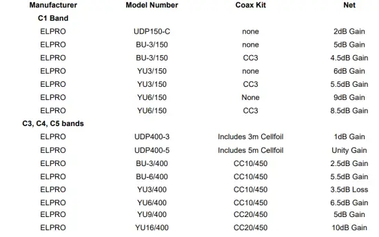
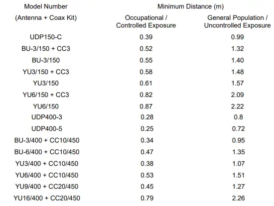
Antenna Models:
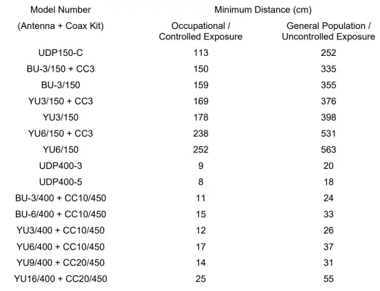
Safety Notices:
FCC (USA)
Exposure to RF energy is an important safety consideration. The FCC has adopted a safety standard for human exposure to radio frequency electromagnetic energy emitted by FCC regulated equipment as a result of its actions in Docket 93-62 and OET Publication KDB 447498 D01. Depending on antenna type, ensure the following minimum separation distances from antennas for (A) Occupational and (B) General Population.
ISED (Canada)
Exposure to RF energy is an important safety consideration. Innovation, Science, and Economic Development Canada (ISED) has adopted a safety standard for human exposure to radio frequency electromagnetic energy emitted by ISED regulated equipment as standard RSS 102 Issue 5. Depending on antenna type, ensure the following minimum separation distances from antennas for (A) Occupational and (B) General Population.
Limitations and Condition of Use:
ELPRO E2-455 radio module is designed as a reusable module for use with future development of ELPRO products. The module is limited for use by ELPRO only. This module is not to be made available for third party use or in any OEM arrangements.
The following requirements apply to any product which incorporates the E2-455 radio module:
The product incorporating the ELPRO E2-455 radio must not include any instructions to remove or install the E2-455 radio module.
The product incorporating the ELPRO E2-455 radio must be limited to installation in mobile or fixed application.
A separate approval is required for all other operating configurations, including portable configurations with respect to Part 2.1093 and different antenna.
Any product incorporating the ELPRO E2-455 radio must include a label on the final product that indicates the certification numbers for the E2-455 radio. The following must appear on the final product label:
C1 band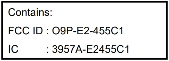
C4 band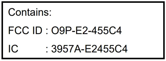
C92 band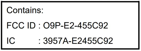
Introduction
The E2-455 is a radio modem module used as a base radio for a number of Elpro wireless products, with additional products to be added in the future. It operates as a wireless network adapter for transfer of 802.11 format data frames over lower speed wireless links. The E2-455 consists of a host microcontroller, an RF transceiver section, and a power supply section.
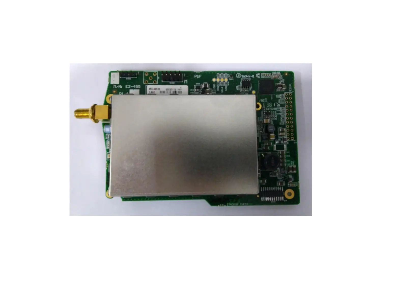
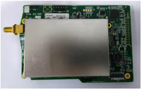
Module Description
Under Side View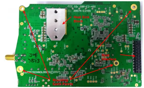
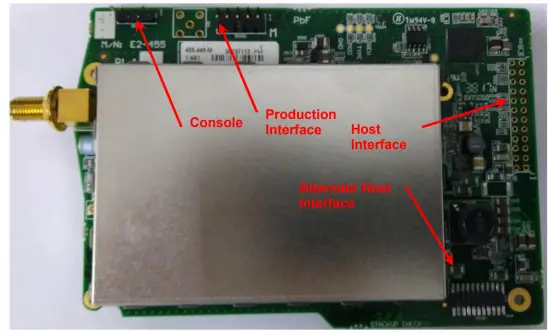
Top Side View
Mounting Points
Four mounting points are provided for 2.5mm Mounting screws.
Heat-Sink Block
A Heat-Sink should be connected to the device’s Heat-Sink block to prevent the power amplifier overheating. The interface to the Heat-Sink block uses two M3 screws separated by 15mm, with engagement depth between 3mm-4mm. Use heat-paste or other heat-conducting material to provide an effective heat conduction path from the heat-sink block to the supplied heat-sink.
Main Host Interface
The main host interface is implemented through a 24-pin socket, allowing connection to standard 0.1″ pitch headers. This interface supplies power to the module as well as the high speed serial connection providing communication to the host device.
Alternate Host Interface
The alternate host interface provides the same functionality as the Main host interface, in a more compact form-factor for use with products requiring a more compact interface.
Production Interface
Production interface consists of a JTAG port for programming and developer debug of the device.
Console Interface
The Console interface allows connection of a serial terminal to the device for diagnostic operation and testing.
Locale
The E2-455 design is capable of supporting frequencies through manufacture of different variants:
- C1 band supports frequency range 148-174MHz.
- C3 band supports frequency range 340-400MHz.
- C4 band supports frequency range 400-480MHz.
- C5 band supports frequency range 470-520MHz.
- C92 band supports frequency range 928-960MHz.
The host software shall implement Locale settings to restrict the range of frequencies, bandwidths and power relevant to the regulations of the specified locale.
The user manual of the product shall state that the unit is to be installed by professional personnel.
United States Locale
The following restrictions on each of the bands apply when US Locale is selected:
| Locale | Frequency Band | Supported Channel Bandwidth |
| FCC_Part90 | 150.8 MHz – 152.855 MHz | 6.25kHz, 12.5kHz, 25kHz |
| FCC_Part90 | 152.855 MHz – 154.0 MHz | 6.25kHz, 12.5kHz, 25kHz |
| FCC_Part90 | 154.0 MHz – 156.2475 MHz | 6.25kHz, 12.5kHz, 25kHz |
| FCC_Part90 | 157.1875 MHz – 157.45 MHz | 6.25kHz, 12.5kHz, 25kHz |
| FCC_Part90 | 157.45 MHz – 161.575 MHz | 6.25kHz, 12.5kHz, 25kHz |
| FCC_Part90 | 161.775 MHz – 161.9625 MHz | 6.25kHz, 12.5kHz, 25kHz |
| FCC_Part90 | 162.0375 MHz – 173.2 MHz | 6.25kHz, 12.5kHz, 25kHz |
| FCC_Part90 | 173.2 MHz – 173.4 MHz | 6.25kHz, 12.5kHz, 25kHz |
| FCC_Part90_B1 | 421.000MHz – 454.000MHz | 6.25kHz, 12.5kHz |
| FCC_Part90_B2 | 456.000MHz – 462.375MHz | 6.25kHz, 12.5kHz |
| FCC_Part90_B3 | 462.7375MHz – 467.5375MHz | 6.25kHz, 12.5kHz |
| FCC_Part90_B4 | 467.7375MHz – 480.000MHz | 6.25kHz, 12.5kHz |
| FCC_Part90 | 928.0 – 930.0MHz | 12.5kHz, 25kHz |
| FCC_Part90 | 935.0 – 940.0MHz | 12.5kHz, 25kHz |
| FCC_Part101 | 928.0 – 929.0MHz | 12.5kHz, 25kHz |
| FCC_Part101 | 932.5 – 935.0MHz | 12.5kHz, 25kHz |
| FCC_Part101 | 941.0 – 960.0MHz | 12.5kHz, 25kHz |
Canada Locale
The following restrictions on each of the bands apply when Canadian Locale is selected:
| Locale | Frequency Band | Supported Channel Bandwidth |
| RSS-119 | 148.000MHz -149.900MHz | 6.25kHz, 12.5kHz, 25kHz |
| RSS-119 | 150.050MHz – 174.000MHz | 6.25kHz, 12.5kHz, 25kHz |
| RSS-119_B1 | 421.000MHz – 430.000MHz | 6.25kHz, 12.5kHz |
| RSS-119_B2 | 450.000MHz – 470.000MHz | 6.25kHz, 12.5kHz |
Operation
The host system communicates with the E2-455 module via the serial interface provided by either the main or alternate host interface. The serial interface is a standard TTL UART interface in full duplex asynchronous connection. The baud rate is 1.0Mbps. RTS and CTS lines are used to provide flow control between the host and radio processors.
The serial protocol is a proprietary message structure.
In addition, a secondary diagnostic interface is provided over the Console interface. This provides the interface for testing the device. It operates at a rate of 115,200 baud.
Diagnostic Interface Command Reference
Radio Commands General
- Set to QAM Mode (Note: par rate command must be re-issued)
> cfg mod qam
0:15:44.891 RAD: CMX7164: Function image 4112 [ OK ]
0:15:45.603 RAD: CMX7164 Rx DC calibration    [ OK ]
[1]               Modulation =         QAM

0:15:45.662 RAD: CMX7164 Tx DC calibration     [ OK ]
- Set to FSK Mode (Note: par rate command must be re-issued)
> cfg mod fsk
0:16:35.955 RAD: CMX7164: Function image 2035  [ OK ]
0:16:36.910 RAD: CMX7164 Rx DC calibration     [ OK ]
[1]          Modulation =      FSK
0:16:36.970 RAD: CMX7164 Tx DC calibration     [ OK ]
(Note: par rate command must be re-issued after every Mode change)
- Set radio transmit modulation format
> par rate 4qam (options 4qam, 16qam, 64qam, 2fsk, 4fsk)
[1]                      Radio frame rate = 4QAM
- Set radio transmit FEC (only in QAM mode) to FEC or RAW
> par fec fec
[1]                    Radio frame FEC =     FEC
> par fec raw
[1]                    Radio frame FEC =     RAW
- Set Radio Channel Bandwidth (6.25kHz, 12.5kHz, 25kHz)
> cfg bw 12500 (Options 6250(QAM only), 12500, 25000)0:35:03.651 RAD: CMX7164 Rx DC calibration [ OK ] [1] Frequency bandwidth = 12500 Hz 0:35:03.694 RAD: CMX7164 Tx DC calibration [ OK ]
- Set Radio Tx and Rx Frequency (in Hz).
> cfg freq_tx 442012500
[1]              Transmit frequency = 442012500 Hz
> cfg freq_rx 442006250
[1]                Receive frequency = 442006250 Hz
- Save Configuration (save all cfg and par items except for rate).
> cfg save- Reset unit.
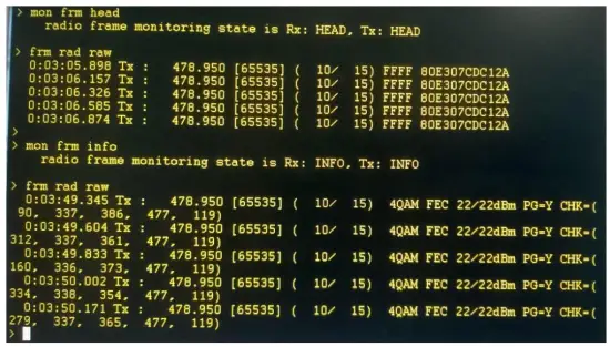
> reset- To change rx/tx monitor).
> mon frm info              Shows more information
> mon frm head              Shows less information
Radio Transmit Commands
- Set Transmit Power for Test commands.
> par txpwr 27
[1]                Transmit power   =      27 dBm
Note: Maximum power is limited according to supply voltage and modulation selected. Power drops by 3dB at approximately 12V supply
- Transmit Repeating 511 bit PRBS
> rad prbs
[1] Radio mode = PRBS, MAC state = TONE, PHY state = TONE, modem state = TONE
- Transmit unmodulated carrier (only available in FSK mode)
> rad tone
[1] Radio mode = TONE, MAC state = TONE, PHY state = TONE, modem state = TONE- To stop transmit sequence, start receiving:
> rad auto
[1] Radio mode = AUTO, MAC state = EMPTY, PHY state = FS, modem state = FS
Frame Transmit Commands
- To Transmit a single message frame (Default repeat is 2, Default Length is 60)
> par repeat 1
[1]             Radio frame repeat count = 1
> par len 10
[1]           Radio frame length = 10
> frm rad raw
20:13:38.777 Tx : 440.000 [65535] ( 10/ 15) FFFF 80E307CDC12A
- To check Frame Receive statistics at receiver
> stat frm clr            Clear frame Statistics counters
> stat frm
[1] RX_ERR_PREAM = 3      Received Preamble, no Frame Sync
[1] RX_ERR_PLCP_HDR = 0   Corrupted Message Header block
[1] RX_ERR_CRC = 0        Received with corrupted Message body
[1] RX_RTS_OTH = 0        Number of Received frames of different types
[1] RX_RTS_ME = 0         RTS to other / Me
[1] RX_CTS_OTH = 0
[1] RX_CTS_ME = 0         CTS to other / Me
[1] RX_ACK_OTH = 0
[1] RX_ACK_ME = 0         ACK to other / Me
[1] RX_UNSPRT = 0         Unsupported Frame Type
[1] RX_MULTI = 0          Multicast Frame
[1] RX_UNI_OTH = 0
[1] RX_UNI_ME = 0        Unicast message to other / Me
To count the number of received frames, add RX_RTS, RX_CTS, RX_ACK, RX_UNSPRT, RX_MULTI and RX_UNI types. When testing with command “frm rad raw”, all received frame should be RX_UNSPRT.
- To Transmit BER Test frames (Default repeat is 8). BER frame length must be > 31 bytes to allow valid testing.
> par len 131 (e.g. for 100 bytes of BER data for each test frame)
> par ber_num 3
[1] Radio BER frame number = 3
> frm rad ber
0:05:40.050 Tx : B 440.000 [65535] ( 60/ 52) D000 FFFFFFFFFFFF 0012AF000000
0:05:40.337 Tx : B 440.000 [65535] ( 60/ 52) D000 FFFFFFFFFFFF 0012AF000000
0:05:40.654 Tx : B 440.000 [65535] ( 60/ 52) D000 FFFFFFFFFFFF 0012AF000000
- To check BER at receiver (Over successfully received BER frames).
> stat ber clr                   Clear BER Statistics counters
> stat ber
[1] Frame number = 0            Number of Received BER frames
[1] Accumulated error bits = 0  Total over all received BER frames
[1] Total bits = 0               Total over all received BER frames
[1] Average RSSI = 0 dB          Average over all received BER frames
[1] Average LQI = 0              Average over all received BER frames
Host Interface Message Framing
Message framing is based on PPP Byte stuffing. The special characters 0x7F, 0x7D and 0xFF are the beginning of a frame, data link escape and end of frame characters respectively. Each message begins with the transmission of the start of frame character. This is followed by the message data payload for the message end of the message is indicated by the end of frame character.
Occurrence of the characters for start of frame, end of frame, or the data link escape character within the data packet is indicated by stuffing an additional data link escape character into the data stream before the special character and then setting bit 5 of the control character to 0. Whenever the start flag character is detected, the framer state is reset to receiving the first data payload byte. (Start flag should never occur in the data payload due to the escaping scheme above.)
The end of frame character ensures that the transmitter and receiver are synchronised at the beginning of the next data frame. If they are not correctly synchronised, the 0xFF will result in the additional “ones” being detected as a long stop condition at the receiver and subsequent characters being correctly synchronised.
Host Interface Message Format
Endian
All multi-byte fields are transmitted in little endian format.
General Message Format
Table 1 describes the general format of the messages including the start and end flags.
| START_FLAG | 1 byte | Start of message identifier (0x7E) |
| Service_code | 2 bytes | Service code to identify message type and message ID |
| Payload Data | 0-n bytes | Message payload data. Interpreted according to Service code |
| END_FLAG | 1 byte | End of message identifier (0xFF) |
Table 1
Service code encoding
Table 2 describes the encoding of the Service code field from the Service Type and Service ID
| b15 – b14 | Service Type 00: request 01: indicate 10: confirm 11: unused |
| b13 – b0 | Service ID 0x41: Transmit 0x42: Flush 0x43: Receive 0x44: Local_Management 0x45: Extended Transmit 0x46: Extended Flush 0x47: Extended Receive |
Table 2
Service types
Table 3 describes the service types and their interactions
| Request (0b00) | Request messages are used where a message acknowledgement is required. A confirm message is expected to be sent from the other party. Matching of request and confirm messages depends on the message ID. Messages may include a unique handle to that can used to match request to confirm, or the process transmitting the message can ensure that only one message of that type is outstanding at any time. |
| Indicate (0b01) | Used when acknowledgement of the message is not required. Indicate messages do not have any matching confirm message. |
| Confirm (0b10) | Confirm messages are returned to the process that initiated a Request message to acknowledge receipt of the request message (and possible acknowledge processing of the request message is complete). Generation of the Confirm message and the details of any payload data depend on the Service ID for the message. The Service ID for the confirm must match the service ID for the original request message. |
Table 3
For more detailed information about the protocol, refer to ELPRO document; spec_E2-Radio-io-protocol
Host Interface Hardware Description
This section describes the interface to the host, including the two alternate power/data interfaces and the earthing connections
Alternate Host Interface Pin Description
| Pin | Signal | Description | Direction |
| 1 | VSupply | 9-30V Supply from host | Input to module |
| 2 | VSupply | 9-30V Supply from host | |
| 3 | VSupply | 9-30V Supply from host | Input to module |
| 4 | GND | Ground | |
| 5 | VSupply | 9-30V Supply from host | Input to module |
| 6 | GND | Ground | |
| 7 | NO_CON | No Connection | |
| 8 | GND | Ground | |
| 9 | NO_CON | No Connection | |
| 10 | GND | Ground | |
| 11 | NO_CON | No Connection | |
| 12 | PG | Power Good Indication | Output from module |
| 13 | NO_CON | No Connection | |
| 14 | nEN_RADIO_PWR | Radio Power Enable | Input to module |
| 15 | NO_CON | No Connection | |
| 16 | RXD0_7 | Data Receive | Output from module |
| 17 | TXD0_7 | Data Transmit | Input to module |
| 18 | CTS0_7 | Clear to Send (When toggled, it indicates that the host should wake up.) | Output from module |
| 19 | RTS0_7 | Ready to Send (When toggled, it indicates that the radio processor should wake up.) | Input to module |
| 20 | Test Point | Not used | |
| 21 | Test Point | Not used | |
| 22 | Test Point | Not used |
Main Host Interface Pin Description
| Pin | Signal | Description | Direction |
| 1 | NC | No Connection | |
| 2 | NC | No Connection | |
| 3 | NC | No Connection | |
| 4 | NC | No Connection | |
| 5 | GND | Ground | |
| 6 | VSUP_CON | Main DC input power supply rail of the host (9-30V) | Input to module |
| 7 | GND | Ground | |
| 8 | VSUP_CON | Main DC input power supply rail of the host (9-30V) | Input to module |
| 9 | MB_CSF | Future Use – Do Not Connect | Output from module |
| 10 | CTS0_7 | Clear to send (When toggled, it indicates that the host should wake up.) | Output from module |
| 11 | MBIRQ | Future Use – Do Not Connect | Input to module |
| 12 | RTS0_7 | Ready to Send (When toggled, it indicates that the radio processor should wake up.) | Input to module |
| 13 | BRX | Future Use – Do Not Connect | Input to module |
| 14 | TXD0_7 | Data Transmit | Input to module |
| 15 | BTX | Future Use – Do Not Connect | Output from module |
| 16 | RXD0_7 | Data Receive | Output from module |
| 17 | _SHDN | Radio Shutdown | Input to module |
| 18 | USBH | Future Use – Do Not Connect | Input to module |
| 19 | nR_OC | Over Current | Output from module |
| 20 | GND | Ground | |
| 21 | USBCX | Future Use – Do Not Connect | Input to module |
| 22 | USBDN | Future Use – Do Not Connect | Input to module |
| 23 | USBDP | Future Use – Do Not Connect | Input to module |
| 24 | NC | No Connection |
Protective Earthing Point
There are four mounting screw points around the cage which are connected to the ground plane of the module. These should be screwed on with metallic screws to the metallic casing or ground points on the host system.
Specifications
| Environmental | |||||||||
| Operating Temperature | -40°C to +70°C (-40 to +120°F) | ||||||||
| Humidity | 0-95% Non-Condensing | ||||||||
| Altitude | 0-2000m / 6500ft | ||||||||
| Radio | |||||||||
| General | Half Duplex UHF radio supports operation on Licensed and Unlicensed bands. | ||||||||
| RF Bands | Channel Spacing | 6.25kHz, 7.5kHz, 12.5 kHz, 20kHz, 25 kHz | |||||||
| Supported Frequency Bands | 148-174MHz 340-400MHz 400-480MHz 470-520MHz 928-960MHz | ||||||||
| Antenna | Single SMA Connector for Receive and Transmit. | ||||||||
| Impedance | 50Ω | ||||||||
| Transmitter | Power Range | 10mW – 10 Watt (+10 to +40 dBm) | |||||||
| Maximum Power Levels with QAM (Power reduction due to Modulation Peak- Average ratio) | Encoding | Max Power | PAPR | ||||||
| 4-QPSK | 4W | 0.4 | |||||||
| 16-QAM | 2.5W | 0.25 | |||||||
| 64-QAM | 2.5W | 0.25 | |||||||
| Data Rates | Data Encoding and Data rates | Channel Encoding | 6.25kHz | 12.5kHz | 25kHz | ||||
| 4-QPSK-FEC | 4kpbs | 8kbps | 16kbps | ||||||
| 4-QPSK | 8kpbs | 16kbps | 32kbps | ||||||
| 16-QAM | 16kbps | 32kbps | 64kbps | ||||||
| 64-QAM | 24kbps | 48kbps | 96kbps | ||||||
| Data Encoding (DFSK Mode for E2-450 compatibility) | Channel Encoding | 12.5kHz | 25kHz | ||||||
| 2-FSK | 4.8kbps | 9.6kbps | |||||||
| 4-FSK | 9.6kbps | 19.2kbps | |||||||
| Receiver | Receiver Sensitivity 6.25/12.5/25kHz channel spacing (BER=1×10⁻⁵) | Encoding | Sensitivity | ||||||
| 4-QPSK-FEC | -116dBm | ||||||||
| 4-QPSK | -110dBm | ||||||||
| 16-QAM | -102dBm | ||||||||
| 64-QAM | -94dBm | ||||||||
| Receiver Sensitivity DFSK Mode 6.25/12.5/25kHz channel spacing (BER=1 x 10⁻⁵) | 2-FSK | -110dBm | |||||||
| 4-FSK | -102dBm | ||||||||
REVISION HISTORY
| Issue No. | Date | Details of Amendment |
| 1.0 | 24/10/2017 | Initial Issue – From E2-450 User Manual |
| 1.1 | 04/02/18 | Update Safe distance limits |
| 1.2 | 08/03/18 | Update Safety notices to include Canada (ISED) specific RF exposure limits. |
| 1.4 | 22/03/18 | Update after CB Review. Notes re OEM installation, application notes. Note on Antenna connectors. Update FCC Exposure table. |
| 1.5 | 08/05/18 | Updates after CB review. Added Canada Locale details. |
| 1.6 | 22/10/2019 | Add C1, C3, C5 bands. |
| 1.7 | 18/11/2019 | For C1 band: Added antennas, cables, FCC and IC safe distance, markings, band, channel spacing. |
| 1.8 | 25/01/2022 | Add C9 band. |