USER MANUAL
UD Series | Thermal Sensor Disks
![]()
121-203756
UD User Manual Revision 1.1
WARRANTY
First Year Warranty
The Gentec-EO thermal disk carry a one-year warranty (from date of shipment) against material and/or workmanship defects when used under normal operating conditions. The warranty does not cover damages related to misuse.
Gentec-EO will repair or replace at our option any disk which proves to be defective during the warranty period; except in the case of product misuse.
Any unauthorized alteration or repair of the product is also not covered by the warranty.
The manufacturer is not liable for consequential damages of any kind.
In the case of a malfunction, contact your local Gentec-EO distributor or the nearest Gentec-EO office to obtain a return authorization number. Return the material to the appropriate address below.
Contacting Gentec Electro-Optics Inc.
To help us answer your calls more efficiently please have the model number of the disk you are using ready before calling Customer Support.
Gentec Electro-Optics, Inc.
445, St-Jean-Baptiste, Suite 160
Québec, QC
Canada, G2E 5N7
Tel: (418) 651-8003
Fax: (418) 651-1174
E-mail: [email protected]
Website: gentec-eo.com
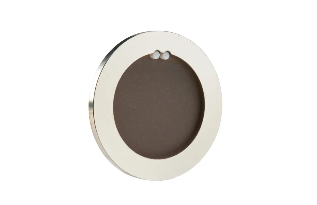
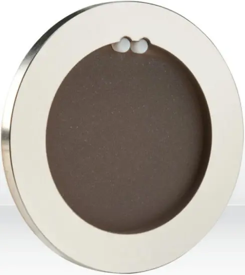
1. ULTRA SERIES UD DISK
1.1. INTRODUCTION
The Gentec-EO UD power detector series includes five opto-thermal sensors (UD10, UD12, UD19, UD25 and UD55). The high power surface absorber sensors are designed for use at high average power densities.
Unit | Aperture | Power range |
| mm | ||
UD10 | 10 | 0.1 mW to 2 W |
| UD12 | 12 | 1 mW to 70 W |
UD19 | 19 | 0.2 mW to 200 W |
| UD25 | 25 | 10 mW to 250 W |
UD55 | 55 | 5 mW to 700 W |
For Gentec-EO’s nearest office contact information, see p. ii, Contacting Gentec Electro-Optics Inc.
1.2. WARNINGS AND DISCLAIMER
In no event shall Gentec-EO or any of its affiliates be liable for any indirect, special, incidental or consequential injury to persons or damage to property caused by the use of any of our products, by purchasing from GentecEO or any of its affiliates, you hereby indicate that you understand and agree to the following:
![]() Disclaimer
Disclaimer
I am fully responsible for the safe application and use of this product and agreed to such by completing the sales process.
I will not use a laser device without wearing approved laser safety goggles designed for such purpose.
I am aware and responsible of safely dealing with any back reflections. I will not use the detector in violation of any local, state or federal law, and I understand that it is my responsibility to know and abide by those laws relating to the ownership and use of the product in my jurisdiction.
1.3. SPECIFICATIONS
The following specifications are based on an operating temperature of 15 to 28ºC (59 to 82ºF) and a relative humidity not exceeding 80%. Disks must be stored in an environment between 10ºC to 65ºC and a relative humidity not exceeding 90%.
| UD10-2-H5-L | ||
| Measurement Capability | ||
| Effective Aperture Diameter | 10 mm | |
| Spectral Range | 0.19 - 20 µm | |
| Typical Power Noise Level¹ | 0.1 mW | |
| Typical Rise Time (0-95%)¹² | 3.0 s | |
| Typical Sensitivity² | 2 mV/W | |
| Energy Mode | ||
| Typical Sensitivity¹ | 2.4 mV/J | |
| Maximum Measurable Energy³ | 3 J | |
| Typical Noise Equivalent Energy¹ | 5 mJ | |
| Damage Thresholds & Laser Limits | ||
| Max. Average Power | 2 W | |
| Max Average Power (Fan Cooled) | 2 W | |
| Maximum Average Power Density 1064 nm, 2 W, CW 10.6 µm, 2 W, CW | 36 kW/cm² 11 kW/cm² | |
| Pulsed Laser Damage Thresholds 1.064 µm, 360 µs, 5 Hz 1.064 µm, 7 ns, 10 Hz 532 nm, 7 ns, 10 Hz 266 nm, 7 ns, 10 Hz | Max. Energy Density 5 J/cm² 1.0 J/cm² 0.6 J /cm² 0.3 J /cm² | Peak Power Density 14 kW/cm² 143 MW/cm² 86 MW/cm² 43 MW/cm² |
| Physical Characteristics | ||
| Dimensions | 44Ø x 3D mm | |
| Weight (Head Only) | 7 g | |
| Recommended Load Impedance | 100 kΩ | |
| Product Number | 202832 | |
Specifications are subject to change without notice
_____________________________
¹ These characteristics depend on the thermal management and electronics provided by the user. Packaging, cooling and electronics similar to our UD Series will provide similar performances. See UD Series specifications sheets for more details. Actual performance depends on the tradeoffs in a user’s design. It may be possible to enhance some performance parameters at the expense of others.
² Without anticipation algorithm or circuitry.
³ For 360 s pulses. Higher pulse energy possible when customized for long pulses (ms), less for short pulses (ns).
| UD12-70-H5 | ||
| Measurement Capability | ||
| Effective Aperture Diameter | 12 mm | |
| Spectral Range | 0.19 - 20 µm | |
| Typical Power Noise Level¹ | 1 mW | |
| Typical Rise Time (0-95%)¹² | 1.6 s | |
| Typical Sensitivity² | 0.53 mV/W | |
| Energy Mode | ||
| Typical Sensitivity¹ | 0.84 mV/J | |
| Maximum Measurable Energy³ | 5 J | |
| Typical Noise Equivalent Energy¹ | 20 mJ | |
| Damage Thresholds & Laser Limits | ||
| Max. Average Power | 70 W | |
| Max Average Power (Fan Cooled) | 30 W | |
| Maximum Average Power Density 1064 nm, 10 W, CW 10.6 µm, 10 W, CW | 36 kW/cm² 11 kW/cm² | |
| Pulsed Laser Damage Thresholds 1.064 µm, 360 µs, 5 Hz 1.064 µm, 7 ns, 10 Hz 532 nm, 7 ns, 10 Hz 266 nm, 7 ns, 10 Hz | Max. Energy Density 5 J/cm² 1.0 J/cm² 0.6 J /cm² 0.3 J /cm² | Peak Power Density 14 kW/cm² 143 MW/cm² 86 MW/cm² 43 MW/cm² |
| Physical Characteristics | ||
| Dimensions | 36Ø x 2D mm | |
| Weight (Head Only) | 4 g | |
| Recommended Load Impedance | 100 kΩ | |
| Product Number | 200382 | |
Specifications are subject to change without notice
_____________________________
¹ These characteristics depend on the thermal management and electronics provided by the user. Packaging, cooling and electronics similar to our UD Series will provide similar performances. See UD Series specifications sheets for more details. Actual performance depends on the tradeoffs in a user’s design. It may be possible to enhance some performance parameters at the expense of others.
² Without anticipation algorithm or circuitry.
³ For 360 s pulses. Higher pulse energy possible when customized for long pulses (ms), less for short pulses (ns).
| UD19-50-W5 | ||
| Measurement Capability | ||
| Effective Aperture Diameter | 19 mm | |
| Spectral Range | 190 nm – 10 µm | |
| Typical Power Noise Level | 1 mW | |
| Typical Rise Time (0-95%)¹² | 5 s | |
| Typical Sensitivity² | 0.65 mV/W | |
| Energy Mode | ||
| Typical Sensitivity¹ | 0.33 mV/J | |
| Maximum Measurable Energy³ | 200 J | |
| Typical Noise Equivalent Energy¹ | 23 mJ | |
| Damage Thresholds & Laser Limits | ||
| Max. Average Power | 50 W | |
| Max Average Power (Fan Cooled) | 50 W | |
| Maximum Average Power Density 1064 nm, 10 W, CW | 100 kW/cm² | |
| Pulsed Laser Damage Thresholds 1.064 µm, 150 µs, 5 Hz 1.064 µm, 7 ns, 10 Hz 532 nm, 7 ns, 10 Hz 266 nm, 26 ns, 10 Hz | Max. Energy Density 100 J/cm² 1.1 J/cm² 1.1 J /cm² 0.7 J /cm² | Peak Power Density 667 kW/cm² 157 MW/cm² 157 MW/cm² 27 MW/cm² |
| Physical Characteristics | ||
| Dimensions | 44Ø x 3D mm | |
| Weight (Head Only) | 7 g | |
| Recommended Load Impedance | 100 kΩ | |
| Product Number | 200761 | |
Specifications are subject to change without notice
______________________________
¹ These characteristics depend on the thermal management and electronics provided by the user. Packaging, cooling and electronics similar to our UD Series will provide similar performances. See UD Series specifications sheets for more details. Actual performance depends on the tradeoffs in a user’s design. It may be possible to enhance some performance parameters at the expense of others.
² Without anticipation algorithm or circuitry.
³ For 360 s pulses. Higher pulse energy possible when customized for long pulses (ms), less for short pulses (ns).
| UD19-…-Hx | UD19-150-H5 | UD19-200-H9 |
| Measurement Capability | ||
| Effective Aperture Diameter | 19 mm | |
| Spectral Range | 190 nm – 10 µm | |
| Typical Power Noise Level¹ | 1 mW | 3 mW |
| Typical Rise Time (0-95%)¹² | 2.8 s | 4.5 s |
| Typical Sensitivity² | 0.65 mV/W | 0.23 mV/W |
| Energy Mode | ||
| Typical Sensitivity¹ | 0.65 mV/J | 0.23 mV/J |
| Maximum Measurable Energy³ | 15 J | 25 J |
| Typical Noise Equivalent Energy¹ | 20 mJ | 60 mJ |
| Damage Thresholds & Laser Limits | ||
| Max. Average Power | 150 W | 200 W |
| Max Average Power (Fan Cooled) | 50 W | 110 W |
| Max. Average Power Density 1.064 µm, 10W CW 10.6 µm, 10W CW | 36 kW/cm² 11 kW/cm² | 45 kW/cm² 14 kW/cm² |
| Pulsed Laser Damage Thresholds 1.064 µm, 150 µs, 5 Hz 1.064 µm, 7 ns, 10 Hz 532 nm, 7 ns, 10 Hz 266 nm, 26 ns, 10 Hz | Max. Energy Density Peak Power Density H5: 5 J/cm², H9: 9 J/cm² H5: 14 kW/cm², H9: 25 kW/cm² 1.0 J/cm² 143 MW/cm² 0.6 J /cm² 86 MW/cm² 0.3 J /cm² 43 MW/cm² | |
| Physical Characteristics | ||
| Dimensions | 44Ø x 3D mm | |
| Weight (Head Only) | 7 g | |
| Recommended Load Impedance | 100 kΩ | |
| Product Number | 200262 | 200576 |
Specifications are subject to change without notice
_____________________________
¹ These characteristics depend on the thermal management and electronics provided by the user. Packaging, cooling and electronics similar to our UD Series will provide similar performances. See UD Series specifications sheets for more details. Actual performance depends on the tradeoffs in a user’s design. It may be possible to enhance some performance parameters at the expense of others.
² Without anticipation algorithm or circuitry.
³ For 360 s pulses. Higher pulse energy possible when customized for long pulses (ms), less for short pulses (ns).
| UD25-…-Hx | UD25-200-H9 | UD25-350-H12 |
| Measurement Capability | ||
| Effective Aperture Diameter | 25 mm | |
| Spectral Range | 190 nm – 10 µm | |
| Typical Power Noise Level¹ | 3 mW | 10 mW |
| Typical Rise Time (0-95%)¹² | 5 s | 7.9 s |
| Typical Sensitivity² | 0.23 mV/W | 0.1 mV/W |
| Energy Mode | ||
| Typical Sensitivity¹ | 0.14 mV/J | 0.05 mV/J |
| Maximum Measurable Energy³ | 40 J | 40 J |
| Typical Noise Equivalent Energy¹ | 200 mJ | 200 mJ |
| Damage Thresholds & Laser Limits | ||
| Max. Average Power | 200 W | 350 W |
| Max Average Power (Fan Cooled) | 150 W | 250 W |
| Max. Average Power Density 1.064 µm, 10W CW 10.6 µm, 10W CW | 45 kW/cm² 14 kW/cm² | |
| Pulsed Laser Damage Thresholds 1.064 µm, 150 µs, 5 Hz 1.064 µm, 7 ns, 10 Hz 532 nm, 7 ns, 10 Hz 266 nm, 26 ns, 10 Hz | Max. Energy Density Peak Power Density 9 J/cm² 25 kW/cm² 1.0 J/cm² 143 MW/cm² 0.6 J /cm² 86 MW/cm² 0.3 J /cm² 43 MW/cm² | |
| Physical Characteristics | ||
| Dimensions | 54Ø x 3D mm | |
| Weight (Head Only) | 13 g | |
| Recommended Load Impedance | >100 kΩ | |
| Product Number | 200263 | 202378 |
Specifications are subject to change without notice
_____________________________
¹ These characteristics depend on the thermal management and electronics provided by the user. Packaging, cooling and electronics similar to our UD Series will provide similar performances. See UD Series specifications sheets for more details. Actual performance depends on the tradeoffs in a user’s design. It may be possible to enhance some performance parameters at the expense of others.
² Without anticipation algorithm or circuitry.
³ For 360 s pulses. Higher pulse energy possible when customized for long pulses (ms), less for short pulses (ns).
| UD55-…-Hx | UD55-200-H9 | UD55-500-H12 | UD55-700-HD |
| Measurement Capability | |||
| Effective Aperture Diameter | 55 mm | ||
| Spectral Range | 190 nm – 20 µm | ||
| Typical Power Noise Level¹ | 5 mW | 15 mW | 45 mW |
| Typical Rise Time (0-95%)¹² | 11 s | 18 s | 14 s |
| Typical Sensitivity² | 0.12 mV/W | 0.06 mV/W | 0.03 mV/W |
| Energy Mode | |||
| Typical Sensitivity¹ | 0.028 mV/J | 0.015 mV/J | 0.008 mV/J |
| Maximum Measurable Energy³ | 200 J | 200 J | 200 J |
| Typical Noise Equivalent Energy¹ | 250 mJ | 250 mJ | 250 mJ |
| Damage Thresholds & Laser Limits | |||
| Max. Average Power | 200 W | 500 W | 700 W |
| Max Average Power (Fan Cooled) | 150 W | 300 W | 400 W |
| Max. Average Power Density 1.064 µm, 10W CW 10.6 µm, 10W CW | 45 kW/cm² 14 kW/cm² | ||
| Pulsed Laser Damage Thresholds 1.064 µm, 150 µs, 5 Hz 1.064 µm, 7 ns, 10 Hz 532 nm, 7 ns, 10 Hz 266 nm, 26 ns, 10 Hz | Max. Energy Density Peak Power Density 9 J/cm² 25 kW/cm² 1.0 J/cm² 143 MW/cm² 0.6 J /cm² 86 MW/cm² 0.3 J /cm² 43 MW/cm² | ||
| Physical Characteristics | |||
| Dimensions | 85Ø x 4D mm | ||
| Weight (Head Only) | 39 g | 39 g | 180 g |
| Recommended Load Impedance | >100 kΩ | ||
| Product Number | 200264 | 201220 | 203757 |
Specifications are subject to change without notice
_____________________________
¹ These characteristics depend on the thermal management and electronics provided by the user. Packaging, cooling and electronics similar to our UD Series will provide similar performances. See UD Series specifications sheets for more details. Actual performance depends on the tradeoffs in a user’s design. It may be possible to enhance some performance parameters at the expense of others.
² Without anticipation algorithm or circuitry.
³ For 360 s pulses. Higher pulse energy possible when customized for long pulses (ms), less for short pulses (ns).
2. MOUNTING AND COOLING RECOMMENDATIONS
Important: Never touch directly the absorbing surface of the thermal disk
2.1. COOLING
The type of cooling (back cover, heat sink, fan, water) and the size of the cooling plate depend on the power applied on the thermal disk. Contact Gentec-EO to discuss your specific application.
Warning: The thermal disk temperature should never exceed 150 °C
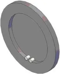
2.2. COOLING PLATE
The thermal disk should be supported by the cooling plate only on the edge of the thermal disk. The cooling plate rim should be made out of a material with a high thermal conductivity. It should also be flat and smooth to allow a good thermal contact with the disk. There should be a gap of at least 6 mm between the back of the disk and any other surface.
THERMAL DISK CONFIGURATION
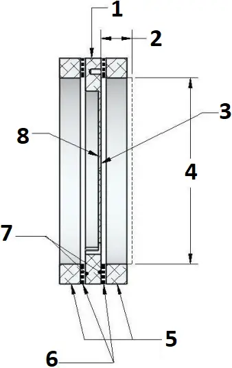
- THERMAL DISK
- 6 mm, MINIMUM AIR GAP BEHIND DISK
- BACK THERMOCOUPLE SIDE OF DISK
- THERMOCOUPLE STAY OUT ZONE
- COOLING MODULES
(CUSTOMER SUPPLIED)
DO NOT MAKE MECHANICAL CONTACT IN THE THERMOCOUPLE STAY OUT ZONE ! - 2X THERMAL PASTE INTERFACE
- 2X MECHANICAL CONTACT AREAS FOR COOLING
(BACK COVER, HEATSINK, FAN, WATER COOLING MODULE) - FRONT ABSORBER FACE OF DISK
2.3. THERMAL DISK MOUNTING
Before mounting the thermal disk in place, a thin film of thermal paste (For example: Wakefield Engineering Inc. thermal paste part no. 120-2.) should be applied on the support rim. Put the disk in place and turn it gently so that a good thermal contact is made between the disk and the support rim. (Be careful not to damage the contact pins.) The thermal disk must be maintained in place from the front (do not apply thermal paste on the front of thermal disk).
2.4. LASER BEAM
The laser beam should always be centered with respect to the center of the thermal disk. The beam diameter should always be smaller than the optical aperture of the disk.
3. SAFETY INSTRUCTIONS
3.1. GENERAL
To ensure a long lifetime of accurate measurements, the thermal disk should be maintained within the following ambient conditions:
Storage environment temperature: 10 to 60°C, RH < 90%
Operating environment temperature: 15 to 28ºC, RH < 80%.
WARNING: Be careful not to exceed the maximum levels and densities stated in the specifications.
It is possible to store and operate your thermal disk beyond this range. For any specific requirements, please contact your local Gentec-EO representative.
For the most accurate measurements, center the beam on the sensor.
3.2. DAMAGE TO THE OPTICAL ABSORBER MATERIAL
Damage to the optical absorber material is usually caused by exceeding the manufacturer’s specifications, such as:
– Incident Average Power Density
– Incident Pulse Energy Density
Refer to the specifications pages for the UD disk specifications. Damage may also be caused if the absorber surface is contaminated. A slight discoloration of the coating does not affect the calibration.
In any case, the beam’s incident area should not be less than 10% of the disk’s aperture. Please contact Gentec-EO to make measurements with such smaller beams.
In the event of significant damage to the coating, some UD Series disk can be recoated. Contact your local Gentec-EO representative for information on repair. See p. ii Contacting Gentec Electro-Optics Inc.
DECLARATION OF CONFORMITY
WEEE compliance
All Gentec-EO products comply with the European Directive 2012/19/EU – WEEE.
RoHS compliance
All Gentec-EO products comply with the European Directive 2011/65/EU – Restriction of Hazardous substance (RoHS 2), except TPM-300.
APPENDIX A: WEEE DIRECTIVE
Recycling and separation procedure for WEEE directive 2002/96/EC
This section is used by the recycling center when the UD disk reaches the end of its life.
The complete thermal disk contains:
1 thermal disk
Separation
Aluminum: Thermal disk Casing
![]()
LEADER IN LASER BEAM MEASUREMENT SINCE 1972
POWER & ENERGY METERS
BEAM PROFILING
THZ MEASUREMENT
CANADA
445 St-Jean-Baptiste, Suite 160
Quebec, QC, G2E 5N7 Canada
T (418) 651-8003
F (418) 651-1174
1 (888) 5GENTEC
(Canada and USA only)
UNITED STATES
5825 Jean Road Center
Lake Oswego, OR, 97035, USA
T (503) 697-1870
F (503) 697-0633
1 (888) 5GENTEC
(Canada and USA only)
JAPAN
Office No. 101, EXL 111 building,
Takinogawa, Kita-ku, Tokyo
114-0023, Japan
T +81-3-5972-1290
F +81-3-5972-1291
CALIBRATION CENTERS
- 445 St-Jean-Baptiste, Suite 160
Quebec, QC, G2E 5N7 Canada - Werner von Siemens Str. 15
82140 Olching, Germany - Office No. 101, EXL 111 building,
Takinogawa, Kita-ku, Tokyo
114-0023, Japan


