Heat Link L6ELBPxxTSx Electric Boiler Panel Manifolds
Disclaimer
HeatLink Group Inc. shall not be responsible for errors in its brochures or printed materials. HeatLink Group Inc. reserves the right to alter its products at any time without notice, provided that alterations to products already on order shall not require material changes in specifi cations previously agreed upon HeatLink Group Inc. and the Purchaser. All trademarks in this material are property of the respective companies. HeatLink and the HeatLink logotype are trademarks of HeatLink Group Inc. All rights reserved.
Product Safety Information
Warnings
The zone control panel is for indoor use only and must be installed by a qualifi ed installer/service technician. This product must be installed and operated in strict accordance with the terms set out in this manual and in accordance with the relevant requirements of the Local Authority Having Jurisdiction. Failure to comply will result in a void of warranty, and may also result in property damage, serious injury, or death.
Servicing
Prior to commencing installation of this panel it is necessary to read and understand all sections of this manual. The symbols below are used throughout this document to ensure proper operation of the panel, and your safety. Please pay attention to these symbols.
In order to avoid injury or death, switch off the power to the panel prior to inspecting or making connections to the terminal strip.
Function
This zone control panel can provide mixing, distribution, and zoning for a wide variety of hydroponic heating applications.
The eff activeness of the system is dependent on the system being designed and installed correctly. Proper consideration of factors such as BTU loads, outdoor design temperature, indoor design temperature, room set-point temperature(s),
differential fluid temperatures, head loss, flow rates, and transfer capacities of the heat emitters is critical.
Once these factors have been considered and the system requirements determined, these can then be evaluated and compared to the panel capabilities.
Note: For boiler operation see the boiler manual included with your ELBP panel.
Unpacking
- Step 1 Examine carton for any damage that may have occurred during shipping. If damage is visible notify your courier and supplier immediately.
- Step 2 Open the carton by removing the staples.
- Step 3 Remove the cardboard spacers from the carton, then remove the panel from the carton. Lift the panel by the base, not the enclosure.
- Step 4 There are two screws holding the cover to the back plate. Remove these with a Philips head screwdriver and put them aside.This panel is heavy; 2-3 person lift required.

Installation Tools Needed
- Level
- Screwdriver or power drill
- Flat head bit
- Phillips head bit # 2
- 2 adjustable wrenches (or 2 × 30mm wrenches)
Panel Specifications
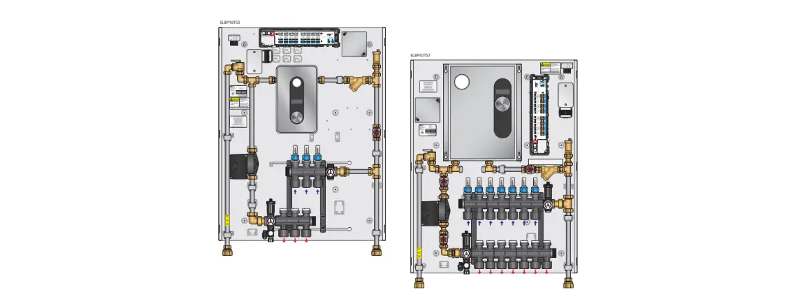
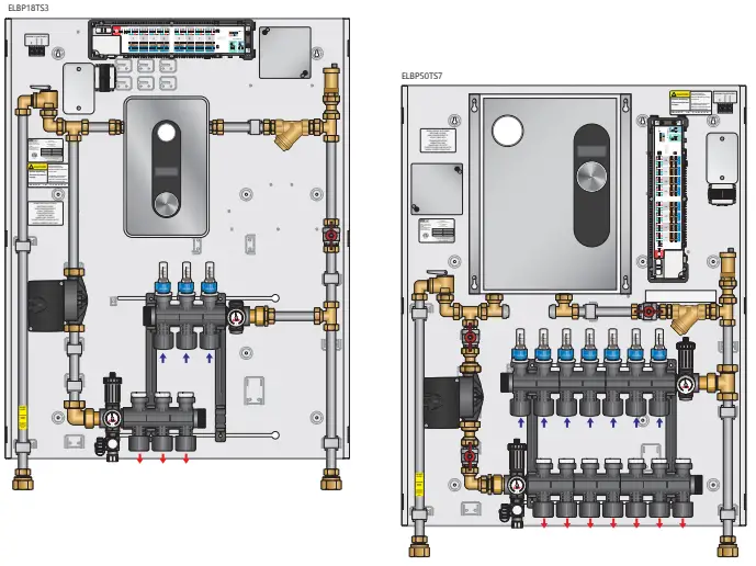
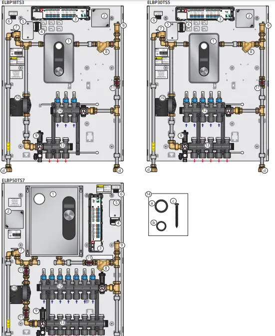
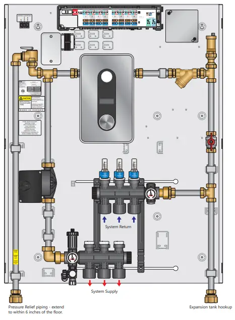
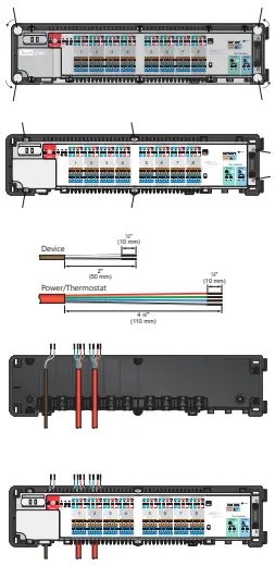
Panel Components (Diagram)
Panel Dimensions
| Enclosure Dimensions | |||
| Stk. # | Height | Width | Depth |
| ELBP18 | |||
| ELBP30 | 371/2” | 291/4” | 43/4” |
| ELBP50 | |||
Panel Components
| # | Components | Component Description | Part Number (Qty.) | |||
| ELBP18TSxx | ELBP30TSxx | ELBP50TSxx | ||||
| 1 | Electric boiler | The electric boiler supplies hot water to the system, and is activated when there is a call for heat via a built in flow switch (see page xx for details). Requires 240V power source. | HA008240 (1) | HA011240 (1) | HA018240 (1) | |
| 2 | Junction box | Wiring connection box for 240V | n/a | n/a | n/a | |
| 3 | StatLink® 8 Zone Wired Module | Connects room thermostats to their corresponding actuators. Each zone has an LED which indicates a call for heat. | 40318 (1) | |||
| 4 | 24Vac Transformer | Supplies 24V power to the StatLink® | (1) | (1) | (1) | |
| 5 | Electrical box | Houses transformer wiring | (1) | (1) | (1) | |
| 6 | Terminal strip | Field wiring connections | (1) | (1) | (1) | |
| 7 | Pressure relief valve | Vents excess system pressure | (1) | (1) | (1) | |
| 8 | Y strainer | Removes entrained air | (1) | (1) | (1) | |
| 9 | Automatic air vent | Automatically vents entrained air | (1) | (1) | (1) | |
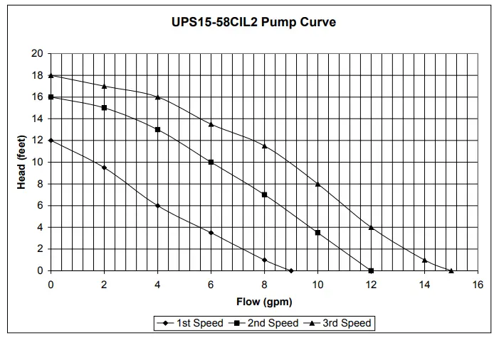
| 10 | Pump | The circulator moves the heated fluid through the hydronic system when there is a call for heat from the thermostat. See pg 6 for pump curve. | PUMP1558 (1) | |||
| 11 | Ball valve | Allows for panel isolation for fill & purge/maintenance | (1) | (1) | (3) | |
| 12 | Return manifold | Modular TwistSeal® manifold for distribution to heating zones | ||||
| 13 | Supply manifold | Modular TwistSeal® manifold for distribution to heating zones | ||||
| 14 | Accessory pack | Installation Acessories | ACCELBP (1) | |||
| a | 1″ nitrile washer | Spare washers for pump | NTRWSH1 (4) | |||
| b | ¾” nitrile washer | Washers for adapters, plus 2 spares for ball valves | NTRWSH34 (8) | |||
| c | Mounting screw | Screws to mount panel to wall | (9) | |||
| d | Piping adapters | ¾”MSBP χ 1″NPT Lead Free adapters | (2) | |||
Specifications & Listings
| Headings | ELBP18TSxx | ELBP30TSxx | ELBP50TSxx |
| Listing | cETLus | ||
| Conforms to | CAN/CSA-C22 No.14, UL508 | ||
| Dimensions | 37.5″ W χ 29.25″ H χ 4.75″ D | ||
| Weight | |||
| Nominal panel output | 18,000 BTU | 30,000 BTU | 50,000 BTU |
| Max ambient temperature | 120ºF | ||
| Max water temperature | |||
| Settable fluid temperature range | 80-140ºF | ||
| Power supply 1 | 110 – 120V | ||
| Power supply 2 | 210 – 240V | ||
| Circulator | Non-ferrous Grundfos 15-58 | ||
| Piping | ¾” Stainless steel tubing | ||
| Piping connections | 1″ FNPT | ||
| Backplate | Galvanized steel | ||
| Enclosure | Powder coated steel |
Panel Installation
Panel Mounting
Prior to mounting the panel, ensure the wall is capable of supporting the weight of the panel, and that the required 110V & 240V wiring is available at the installation location. See page xx for wiring details.The top of the panel should be a minimum of 5 feet from the floor, with sufficient space left at the bottom for required piping.
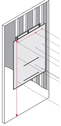
- Step 1 Using a level at the minimum height of 5 feet, draw a straight line on the wall.
- Step 2 Mark stud locations. If the panel cannot be secured directly to the studs, a backing board may be needed to properly install the panel.
- Step 3 Screw three of the supplied mounting screws into the studs or backing board 3″ from the desired height, 6″ and 16″ apart (see diagram).
- Step 4 Lift and place the panel onto the mounting screws using the keyhole slots.
- Step 5 Screw the remaining mounting screws into place, and tighten all screws.
- Step 6 Refer to piping hookup, fill and purge, and wiring instructions before replacing the cover.
Piping Hookup
- Step 1 Identify the piping connections on the panel. You will need 2x 30mm, or large adjustable or smooth jaw pipe wrenches to tighten the fittings.
- Step 2 Ensure that the panel is mounted in the correct position
- Step 3 Connect the 2 adapters to the supply and return piping on the panel, using the supplied washers. Do not overtighten the panel connections, as this will damage the rubber washers.
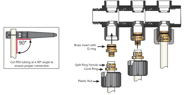
- Step 4 Attach the PEX tubing to the manifold connection using #77000 series connectors (not included).

- Step 5 Remove the plastic manifold nut.
- Step 6 Lubricate the inside of the manifold port with silicone o-ring lubricant (#79952).
- Step 7 Cut the PEX tubing at a 90º angle.
- Step 8 Place the plastic manifold nut, cone ring, and split ring ferrule onto the PEX tubing (the bevelled edge of the cone ring must be facing the split ring ferrule).
- Step 9 Method A
- Push the brass insert onto the PEX tubing as far as it will go.
- Push the PEX tubing with the brass insert as far as it will go into the manifold. Ensure that the o-ring is clean and take care not to pinch it.
- Step 10 Method B
- Push brass insert as far as it will go into the manifold. Ensure the o-ring is clean and take care not pinch it.
- Push PEX tubing onto the brass insert as far as it will go.
- Step 11 Use the multi-pupose wrench to tighten the nut.
Piping Hookup (Diagram)
Fill & Purge
The following steps are recommended in order to fill the panel with water and purge entrained aironce piping is completed, and before activation of the panel.
Note: Additional purging steps may be required for the rest of the system.
The discharged system fluid from the fill and purge process is not for consumption or washing.

- Step 1 Ensure the panel is not powered.
- Step 2 Close valve J, or ensure expansion tank piping is closed/plugged.
- Step 3 Fully close valves A, C, F, G, H. Plug pressure relief valve B for fill and purge only.
- Step 4 Fully close all Supply D and Return E manifold valves.
- Step 5 Attach purge hose (not included) to C; run hose to bucket or drain.
- Step 6 Attach fill hose (not included) to A.
- Step 7 Open first Return manifold E valve, and first Supply manifold D valve.
- Step 8 Open valves C and A.
- Step 9 Watch the purge hose in the pail until you observe a steady stream of water (no air or spitting).
- Step 10 Close the first Return manifold E valve and the first Supply manifold D valve.
- Step 11 Repeat for each loop in the system.
- Step 12 Once each loop has been filled, close all supply and return manifold valves.
- Step 13 Open valves F, G, H.
- Step 14 Watch the purge hose in the pail until you observe a steady stream of water (no air or spitting).
- Step 15 Open valve J.
- Step 16 Close valve C.
- Step 17 Open all Supply D and Return E manifold valves; fill the system to the required operating pressure.
- Step 18 Close valve A.
- Step 19 Remove plug from B.
- Step 20 Check for leaks at connections. If any leaks are found, tighten the connection (using a backup wrench
on SS & brass connections) slowly until leak stops.
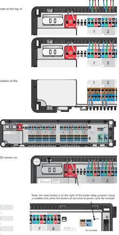
Thermostat & Actuator Wiring
- Step 1
Remove the plastic cover. Open (and close) the four white screws with a quarter turn only. Note that screws on opposite sides turn in the opposite direction. - Step 2
Remove the white terminal connection board by removing the six screws shown below. Take precautions not to remove the 24V power cable, or the pump and boiler cables. - Step 3
Cut the thermostat, and actuator cables to length. - Step 4
Clip all power and thermostat cables into their correct positions. The following shows the power, zone 1, and 2 thermostat cables in position: - Step 5
Replace the white terminal connection board.
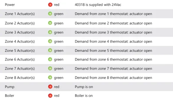
- Step 6 Bend over and push all thermostat wires into the round holes at the top of the module
- Step 7 Push the actuator wires into the round holes at the bottom of the module. Clip wires into the strain relief.
You can connect up to four actuators in each zone. - Step 8 Replace the plastic cover.
- Step 9 Switch on mains power supply to the unit. The red LED comes on.

40318 LED Indications
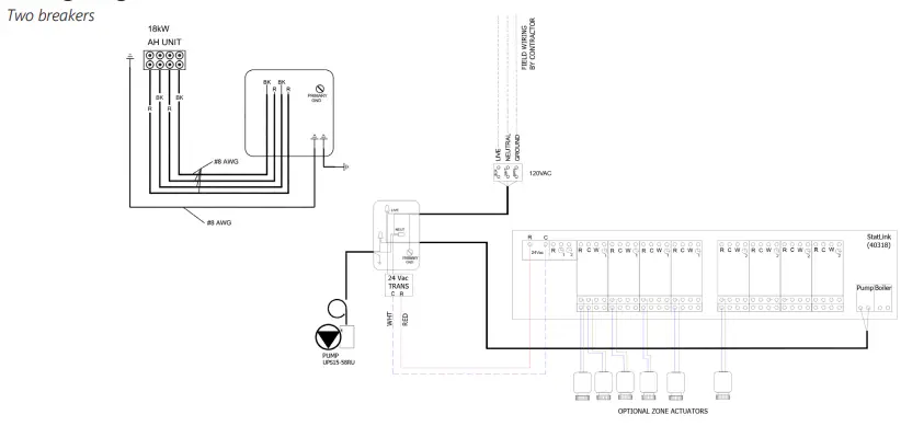
Panel Control Sequence & Wiring
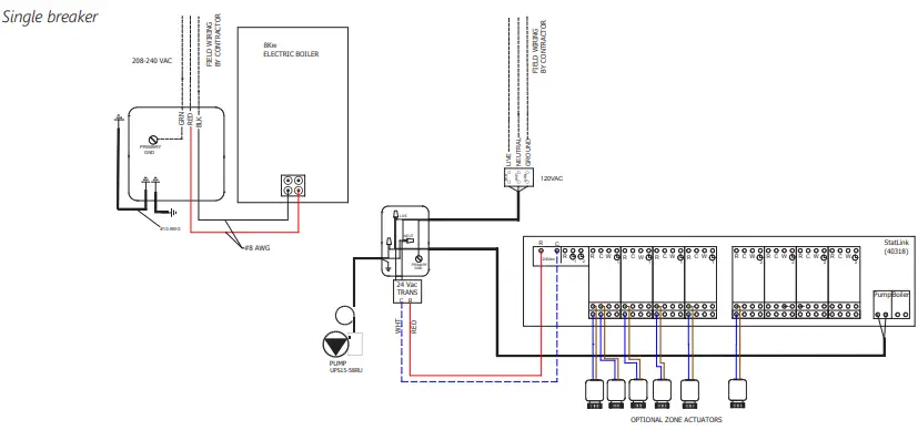
- Two (2) Double Pole 50 Amp circuit breakers must be installed in the main electrical panel.
- All wiring should be done by a qualified electrician, and should meet local codes and jurisdictions.
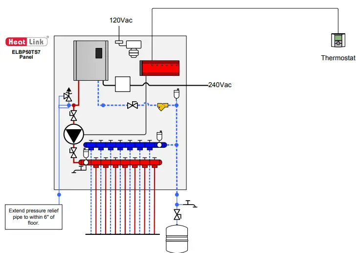
- HeatLink® ELBP panels require two (2) seperate power sources: 120V to power the pump, and via the 24Vac transformer, the StatLink®, and actuators (optional, sold seperately); and 240V to power the electric boiler. Both power sources must be connected for the ELBP panel to function properly.
- Refer to the wiring diagram below.
- When there is a call for heat from the thermostats wired to the StatLink® 8 Zone Wired Module, a relay is switched on, activating the pump; the electric boiler is then activated via a flow meter and supplies heat based on the user settings.
- Note: A timer thermostat (46645) can send a setback signal to other thermostats via terminal Clock 1 or 2.
Wiring Diagram
Two breakers
Single breaker
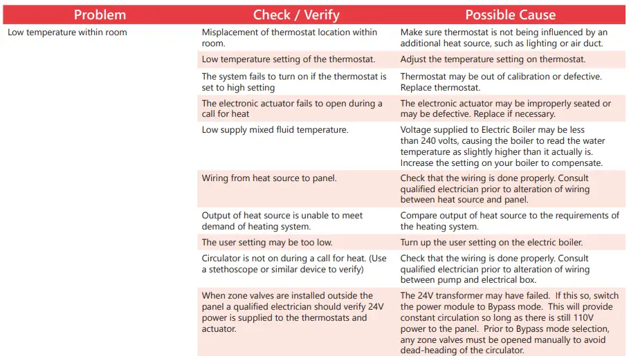
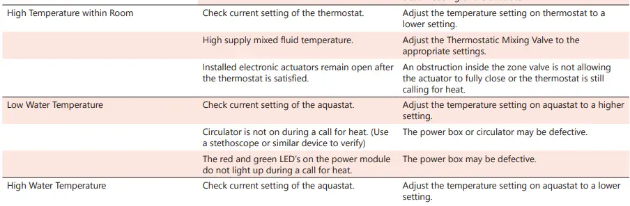
Troubleshooting
NOTE
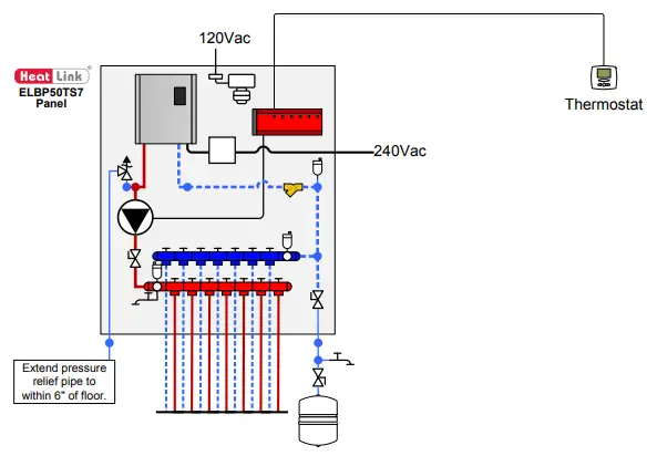
- Drawings are for HeatLink suggested system layout only! User must determine if system layout will work for their particular application.
- Air vents, expansion tanks, pressure relief valves, etc. for heat source as per local codes.
- Use isolation ball valves for all circuits and components.
- Local codes, regulations, and authorities have final jurisdiction.
1-866-661-5332


