BAXI 424 Combi 2 – 430 Combi 2 High Efficiency Wall Hung Condensing Gas Boiler
Product Information
The High-efficiency wall-hung condensing gas boiler is a safe and efficient appliance designed for heating purposes. The boiler is available in different models such as 424 Combi 2, 430 Combi 2, 424 Combi LPG 2, and 430 Combi LPG 2. The product comes with a user manual that contains detailed instructions for safe usage and maintenance.
The product is suitable for use by children aged 8 years and above, and by persons with reduced physical, sensory or mental capabilities or lack of experience and knowledge when they have been given supervision or instruction concerning the safe use of the device and understand the resulting risks. Children must not be allowed to play with the appliance. Cleaning and user maintenance must not be carried out by children without supervision.
Product Usage Instructions
Before using the product, please read through the manual carefully and keep it in a safe place for later reference. In order to ensure continued safe and efficient operation, we recommend that the product is serviced regularly. Our service and customer service organization can assist with this.
Accessing USER Parameters
To access USER parameters, follow these steps:
- Go to Settings.
- Select Access to USER parameters.
List of USER Parameters
The following are the USER parameters:
- Filling the installation
- Venting the installation
Maintenance Message
The product comes with a maintenance message that appears when it needs servicing. When you see this message, please contact our service and customer service organization for assistance.
Fault Finding
If you experience any issues with the product, please refer to the Fault Finding section in the manual for assistance.
Decommissioning Procedure
If you need to decommission the product, please follow the procedure outlined in the manual. This includes shutting off the gas supply and disconnecting the electrical supply.
Disposal and Recycling
Please dispose of the product in accordance with local regulations. Contact your local authority for information on recycling options.
Please keep these instructions in a safe place. If you move house, please hand them over to the next occupier.
Dear Customer,
Thank you very much for buying this appliance. Please read through the manual carefully before using the product, and keep it in a safe place for later reference. In order to ensure continued safe and efficient operation we recommend that the product is serviced regularly. Our service and customer service organisation can assist with this.
We hope you enjoy years of problem-free operation with the product
Safety
General safety instructions
This boiler can be used by children aged 8 years and above and by persons with reduced physical, sensory or mental capabilities or lack of experience and knowledge when they have been given supervision or instruction concerning the safe use of the device and understand the resulting risks. Children must not be allowed to play with the appliance. Cleaning and user maintenance must not be carried out by children without supervision.
If you smell gas:
- Turn off the gas supply at the meter.
- Open windows and doors in the hazardous area.
- Do not operate light switches.
- Do not operate any electrical equipment.
- Do not use a telephone in the hazardous area.
- Extinguish any naked flame and do not smoke.
- Warn any other occupants and vacate the premises.
- Telephone the National Gas Emergency Service on:- 0800 111 999.
Important
If a water or gas leak occurs or is suspected, the boiler can be isolated at the inlet valves by turning their taps through 90° (1/4 turn) downwards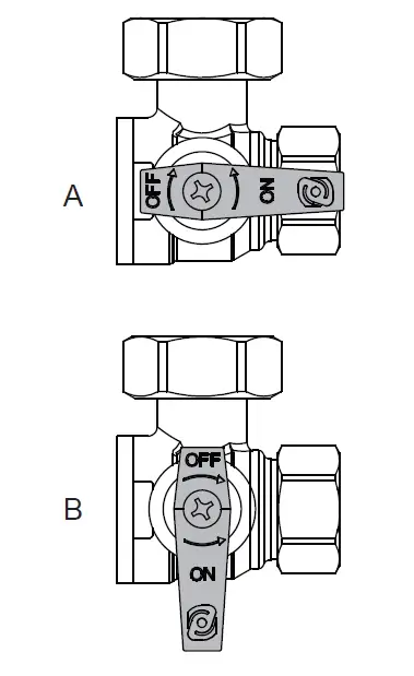
- A ON
- B OFF
For advice please contact your Installer, Annual Service Provider or Baxi Customer Support – The Service Division of Baxi. You can contact Baxi Customer Support on telephone number 0344 871 1545.
When contacting Baxi Customer Support it will be useful to have the “Benchmark Checklist ” at the back of the Installation & Service Manual to hand as it includes details relevant to the boiler and installation.
Warning
- Do not touch flue/chimney pipes. Depending on the settings of the appliance, the temperature of flue/chimney pipes may exceed 60 °C.
- Do not touch radiators for long periods. Depending on the settings of the appliance, the temperature of radiators may reach 85 °C.
- Take precautions with domestic hot water. Depending on the settings of the appliance, domestic hot water temperature may reach 65 °C.
Caution
Do not neglect to service the appliance. Contact a qualified professional or take out a maintenance contract for the annual servicing of the appliance.
Recommendations
- Only qualified professionals are authorised to work on the boiler and the installation.
- The appliance has an integral frost protection mode as long as there is power to the boiler
Important
- Regularly check the water pressure in the system (recommended pressure is 1.5 bar).
- Keep the appliance accessible at all times.
- Do not remove or cover the user information and serial number labels affixed to the boiler control flap. They must remain legible throughout the lifetime of the boiler
The Benchmark Scheme
Baxi Heating UK Ltd is a licensed member of the Benchmark Scheme which aims to improve the standards of installation and commissioning of domestic heating and hot water systems in the UK and to encourage regular servicing to optimise safety, efficiency and performance. Benchmark is managed and promoted by Heating and Hotwater Industry Council. For more information visit www.centralheating.co.uk
Benchmark Commissioning Checklist
- Please ensure that the installer has fully completed the Benchmark Checklist on the inside back pages of the installation instructions supplied with the product and that you have signed it to say that you have received a full and clear explanation of its operation. The installer is legally required to complete a commissioning checklist as a means of complying with the appropriate Building Regulations (England and Wales).
- All installations must be notified, by the installer, to Local Area Building Control either directly or through a Competent Persons Scheme. A Building Regulations Compliance Certificate will then be issued to the customer who should, on receipt, write the Notification Number on the Benchmark Checklist.
- This product should be serviced annually to optimise its safety, efficiency and performance. The service engineer should complete the relevant section of the Benchmark Service Record in the Installation & Service manual after each service.
- The completed Benchmark Checklist & proof of annual servicing (where applicable) will be required in the event of any warranty work.
Liabilities
User’s liability
- To guarantee optimum operation of the system, you must abide by the following instructions:
- Read and follow the instructions given in the manuals provided with the appliance.
- Call on a qualified professional to carry out installation and initial commissioning.
- Get your installer to explain your installation to you.
- Have the required inspections and maintenance carried out by a qualified installer.
- Keep the instruction manuals in good condition close to the appliance.
Installer’s liability
- The installer is responsible for the installation and initial commissioning of the appliance. The installer must observe the following instructions:
- Read and follow the instructions given in the manuals provided with the appliance.
- Install the appliance in compliance with prevailing legislation and standards.
- Carry out initial commissioning and any checks necessary.
- Explain the installation to the user.
- If maintenance is necessary, warn the user of the obligation to check the appliance and keep it in good working order.
- Give all the instruction manuals to the user.
Manufacturer’s liability
- Our products are manufactured in compliance with the requirements of the various Directives applicable. They are therefore delivered with the marking and any documents necessary. In the interests of the quality of our products, we strive constantly to improve them. We therefore reserve the right to modify the specifications given in this document.
- Our liability as manufacturer may not be invoked in the following cases:
- Failure to abide by the instructions on installing and maintaining the appliance.
- Failure to abide by the instructions on using the appliance.
- Faulty or insufficient maintenance of the appliance.
About this manual
General
- Installation, repair and maintenance must only be carried out only by a competent person.
- All Gas Safe registered engineers carry an ID card with their licence number and a photograph. You can check your engineer is registered by telephoning 0800 408 5500 or online at www.gassaferegister.co.uk
- This manual is intended for the user of the Baxi 400 Combi 2 boiler. If the appliance is sold or transferred, or if the owner moves leaving the appliance behind you should ensure that the manual is kept with the appliance for consultation by the new owner and their installer.
- The appliance is designed as a boiler for use in residential domestic environments on a governed meter supply only. The selection of this boiler is entirely at the owner’s risk. If the appliance is used for purposes other than or in excess of these specifications, the manufacturer will not accept any liability for resulting loss, damage or injury.
- The manufacturer will not accept any liability whatsoever for loss, damage or injury arising as a result of failure to observe the instructions for use, maintenance and installation of the appliance.
Additional documentation
Various timers, external controls, etc. are available as optional extras. Fulldetails are contained in the relevant sales literature
Symbols used
This manual uses various danger levels to draw attention to special instructions. We do this to improve user safety, to prevent problems and to guarantee correct operation of the appliance.
- Danger
Risk of dangerous situations that may result in serious personal injury. - Danger of electric shock
Risk of electric shock. - Warning
Risk of dangerous situations that may result in minor personal injury. - Caution
Risk of material damage. - Important
Please note: important information. - See
Reference to other manuals or pages in this manual.
Abbreviations/glossary
- CH Central heating
- DHW Domestic hot water
- PCU PCB for managing burner operation
- Pnc Condensing output
- SU Safety PCB
Technical specifications
Homologations
| UKCA certificate number | 748363 |
| NOx class | 6 |
| Boiler type | C13, C33 |
Important
All data in these sections are nominal and subject to normal pro duction tolerances.
Technical data
| Baxi Combi 2 | 424 | 430 | 424 LPG | 430 LPG | ||
| Gas Council numbers | 47-077-51 | 47-077-52 | 47-077-53 | 47-077-54 | ||
| Condensing boiler | Yes | Yes | Yes | Yes | ||
| Low-temperature boiler(1) | No | No | No | No | ||
| B1 boiler | No | No | No | No | ||
| Cogeneration space heater | No | No | No | No | ||
| Combination heater | Yes | Yes | Yes | Yes | ||
| Rated heat output | Prated | kW | 20 | 20 | 20 | 20 |
| Useful heat output at rated heat output and high temperature setting (2) | P4 | kW | 20 | 20 | 20 | 20 |
| Useful heat output at 30% of rated heat out-put and low temperature setting(1) | P1 | kW | 6.7 | 6.7 | 6.7 | 6.7 |
| Seasonal space heating energy efficiency | ƞs | % | 93 | 93 | 93 | 93 |
| Useful efficiency at rated heat output and high temperature setting(2) | ƞ4 | % | 88.2 | 88.0 | 88.2 | 88 |
| Useful efficiency at 30% of rated heat output and low temperature setting(1) | ƞ1 | % | 97.9 | 97.8 | 97.9 | 97.8 |
| Auxiliary electricity consumption | ||||||
| Full load | elmax | kW | 0.037 | 0.026 | 0.037 | 0.026 |
| Partial load | elmin | kW | 0.014 | 0.014 | 0.014 | 0.014 |
| Standby mode | PSB | kW | 0.004 | 0.004 | 0.004 | 0.004 |
| Other items | ||||||
| Heat loss on standby | Pstby | kW | 0.04 | 0.04 | 0.04 | 0.04 |
| Ignition burner power consumption | Pign | kW | – | – | – | – |
| Annual energy consumption | QHE | GJ | 62 | 62 | 62 | 62 |
| Sound power level, indoors | LWA | dB | 50 | 49 | 50 | 49 |
| Nitrogen oxide emissions | NOx | mg/kWh | 24 | 21 | 21 | 21 |
| Domestic hot water parameters | ||||||
| Declared load profile | XL | XL | XL | XL | ||
| Daily electricity consumption | Qelec | kWh | 0.176 | 0.189 | 0.176 | 0.189 |
| Annual electricity consumption | AEC | kWh | 39 | 42 | 39 | 42 |
| Water heating energy efficiency | ƞwh | % | 88 | 89 | 88 | 89 |
| Daily fuel consumption | Qfuel | kWh | 22.03 | 21.66 | 22.03 | 21.66 |
| Annual fuel consumption | AFC | GJ | 17 | 17 | 17 | 17 |
| (1) Low temperature means for condensing boilers 30°C, for low temperature boilers 37°C and for other heaters 50°C return temperature (at heater inlet). (2) High temperature setting means 60 °C return temperature at boiler inlet and 80 °C flow temperature at boiler outlet | ||||||
General
| 424 | 430 | 424 LPG | 430 LPG | ||
| Rated heat input (Qn) for domestic hot water | kW | 24.7 | 30 | 24.7 | 30 |
| Rated heat input (Qn) with domestic hot water tank | kW | – | – | – | – |
| Rated heat input (Qn) for heating | kW | 20.6 | 20.6 | 20.6 | 20.6 |
| Reduced heat input (Qn) 80/60 °C | kW | 4.9 | 6.0 | 4.9 | 6 |
| Rated heat output (Pn) for domestic hot water | kW | 24 | 29.1 | 24 | 29.1 |
| Rated heat output (Pn) with domestic hot water tank | kW | – | – | – | – |
| Rated heat output (Pn) 80/60 °C for heating | kW | 20 | 20 | 20 | 20 |
| Rated heat output (Pn) 50/30 °C for heating | kW | 21.8 | 21.8 | 21.8 | 21.8 |
| Reduced heat output (Pn) 80/60 °C | kW | 4.8 | 5.8 | 4.8 | 5.8 |
| Reduced heat output (Pn) 50/30 °C | kW | 5.2 | 6.3 | 5.2 | 6.3 |
| Rated efficiency 50/30 °C (Hi) | % | 105.8 | 105.8 | 105.8 | 105.8 |
Characteristics of the heating circuit
| 424 | 430 | 424 LPG | 430 LPG | ||
| Maximum pressure | bar | 2.5 | 2.5 | 2.5 | 2.5 |
| Minimum pressure | bar | 0.5 | 0.5 | 0.5 | 0.5 |
| Temperature range for heating circuit | °C | 25 – 80 | 25 – 80 | 25 – 80 | 25 – 80 |
| Water capacity of expansion vessel | l | 7 | 7 | 7 | 7 |
Characteristics of the domestic water circuit
| 424 | 430 | 424 LPG | 430 LPG | ||
| Minimum pressure | bar | 0.8 | 0.8 | 0.8 | 0.8 |
| Maximum pressure | bar | 8.0 | 8.0 | 8 | 8 |
| Minimum dynamic pressure | bar | 0.15 | 0.15 | 0.15 | 0.15 |
| Minimum water flow | l/min | 2.0 | 2.0 | 2 | 2 |
| Specific flow (D) | l/min | 11.5 | 14 | 11.5 | 14 |
| Temperature range for domestic water circuit | °C | 35 – 60 | 35 – 60 | 35 – 60 | 35 – 60 |
| Domestic water production with ΔT = 25 °C | l/min | 13.8 | 16.7 | 13.8 | 16.7 |
| Domestic water production with ΔT = 35 °C | l/min | 9.8 | 11.9 | 9.8 | 11.9 |
Combustion characteristics
| 424 | 430 | 424 LPG | 430 LPG | ||
| G20 gas consumption (Qmax) | m3/h | 2.61 | 3.17 | 2.61 | 3.17 |
| G20 gas consumption (Qmax) with domestic hot water tank | m3/h | – | – | – | – |
| G20 gas consumption (Qmin) | m3/h | 0.52 | 0.63 | 0.52 | 0.63 |
| G31 propane gas consumption (Qmax) | kg/h | – | – | 1.92 | 2.33 |
| G31 propane gas consumption (Qmin) | kg/h | – | – | 0.38 | 0.47 |
| Diameter of separate discharge pipes | mm | 80/80 | 80/80 | 80/80 | 80/80 |
| Diameter of coaxial discharge pipes | mm | 60/100 | 60/100 | 60/100 | 60/100 |
| Flue gas mass flow rate (max) | kg/sec | 0.011 | 0.014 | 0.011 | 0.014 |
| Flue gas mass flow rate (max) with domestic hot water tank | kg/sec | – | – | – | – |
| Flue gas mass flow rate (min) | kg/sec | 0.002 | 0.003 | 0.002 | 0.003 |
Electrical characteristics
| 424 | 430 | 424 LPG | 430 LPG | ||
| Power supply voltage | V | 230 | 230 | 230 | 230 |
| Power supply frequency | Hz | 50 | 50 | 50 | 50 |
| Rated electric power | W | 90 | 90 | 90 | 90 |
| Rated electrical output with domestic hot water tank | W | – | – | – | – |
Other characteristics
| 424 | 430 | 424 LPG | 430 LPG | ||
| Humidity protection rating (EN 60529) | IP | X5D | X5D | X5D | X5D |
| Net weight when empty/filled with water | kg | 28/30 | 29/31 | 28/30 | 29/31 |
| Dimensions (height/width/depth) | mm | 700/395/285 | 700/395/285 | 700/395/285 | 700/395/285 |
Dimensions and connections/clearances
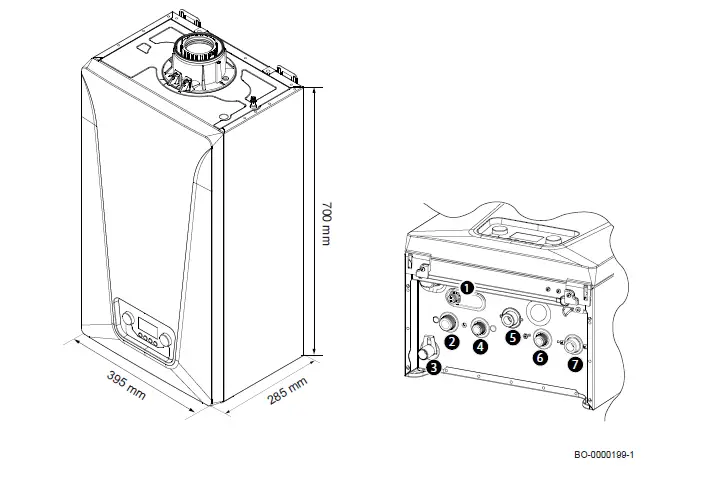
- Safety valve
- Heating circuit flow fitting (G3/4”)
- Fitting for condensate discharge 4567
- DHW (Domestic Hot Water) outlet fitting (G1/2”)
- Gas inlet fitting (G3/4”)
- Domestic cold water inlet fitting (G1/2”)
- Heating circuit return fitting (G34″)
Description of the product
General description
The purpose of this gas-fuelled condensing boiler is to heat water to a temperature that is lower than boiling point at atmospheric pressure. It must be connected to a heating installation and to a domestic hot water distribution system that is compatible with its power and performance ratings. Features of this boiler:
- Low pollutant emissions,
- High-efficiency heating,
- Front control panel with display,
- Lightweight and compact
Operating principle
Air-gas adjustment
The air is drawn in by the fan and gas injected directly at the height of the venturi. The fan revolution speed is regulated automatically by the electronic board based on the adjustment settings. The gas and air are mixed in the manifold. The gas/air ratio ensures that the quantity of gas and air are adjusted correctly to always obtain optimal combustion. The gas/air mixture is fed into the burner at the front of the exchanger. Here, the electric igniter triggers the mixture with a series of sparks that burn, producing thermal energy.
Combustion
The burner heats the heating water circulating in the heat exchanger. When the temperature of the combustion gas is lower than the dew point (around 55 °C), the water vapour contained in the combustion gas condenses in the flue gas side of the heat exchanger. The heat recovered during this condensation process (the latent heat or condensing heat) is also transferred to the heating water. Once cooled, the combustion gases are discharged through the exhaust pipe. The condensed water is discharged through a siphon.
Heating and domestic hot water production
In boilers used for heating and for producing domestic hot water, an integrated plate heat exchanger heats the domestic water. The heated water is then channelled to the heating installation or to the plate heat exchanger via a three-way valve. A flow sensor detects that a hot water tap has been turned on and communicates this to the PCB, which switches the three-way valve to the hot water position and activates the pump. The three-way valve is spring-loaded and only consumes electricity when switching from one position to another. Precedence is given to a heat request in domestic water mode.
Control panel description
Description of the control panel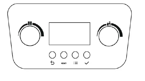
Knobs
 HEATING: Using this knob you can modify the flow temperature for the heating installation (heating setpoint 25-80 °C). turn the knob anti-clockwise to reduce the temperature or to the left to scroll through the menus. With an outside sensor connected it is possible to limit the setpoint value; turn the knob clockwise to increase the temperature or to the right to scroll through the menus.
 DOMESTIC HOT WATER: Using this knob you can modify the domestic hot water temperature (DHW setpoint 35-60 °C) or scroll through the menus to the left and right: turn anti-clockwise to reduce the temperature. turn clockwise to increase the temperature
Icons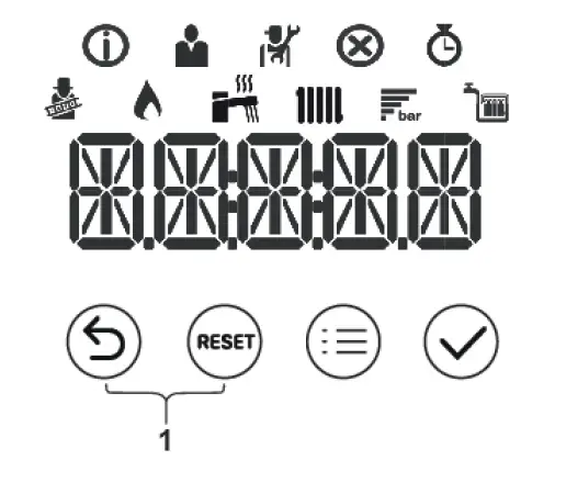
![]()
- Chimney sweep mode is enabled (forced full load or low load for CO2 measurement).
- The burner is on.
- Display of the system water pressure.
- DHW operation is enabled.
- CH operation is enabled.
- Information menu: read out various current values.
- User menu: user-level parameters can be configured.
- Installer menu: installer-level parameter can be configured.
- Error menu: errors can be read out.
- Counter menu: various counters can be read out.
Buttons
![]()
- Back (previous menu)
- Manual reset
- Menu
- Confirms selection or value.
- Chimney sweep mode: Press the Back and Manual reset keys simultaneously
Accessories & options
Consult the sales catalogue for all available accessories and options.
Operation
Start-up
Procedure for first start-up
The following information appears on the display when the boiler is electrically powered:
- The message “INIT”” appears, indicating that the “Initialisation” phase is active (a few seconds);
- The software version “Vxx.xx.” appears (two seconds);
- The software version for boiler settings “Pxx.xx.” appears (two seconds);
- The boiler and heating installation venting phase has started. During operation, the display shows in alternate mode “– – – – – – – –”, the word “DEAIR” and the pressure value for the heating circuit. This phase lasts 6 minutes and 20 seconds, at the end the boiler is ready for operation;
- The
 symbol and the “x.x” installation water pressure value appear.
 - In the event of a power outage the procedure will be repeated from the beginning.
- To activate a heating request, the room thermostat must be set to a temperature above the current temperature (or open a domestic water tap.)
Changing the heating flow temperature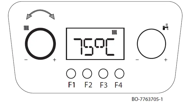
- Use the knob to adjust the flow temperature in heating mode.
- Turn the knob anti-clockwise to reduce the temperature value.
- Turn the knob clockwise to increase the temperature value.
Important
With an outside sensor connected it is possible to lower the setpoint value.
- Press the F4 key to confirm the value or wait a few seconds until the value is automatically saved.
Important
The flow temperature on the display automatically matches the temperature set when using a:
- Weather-dependent regulator.
- OpenTherm regulator
Changing the domestic hot water (DHW) temperature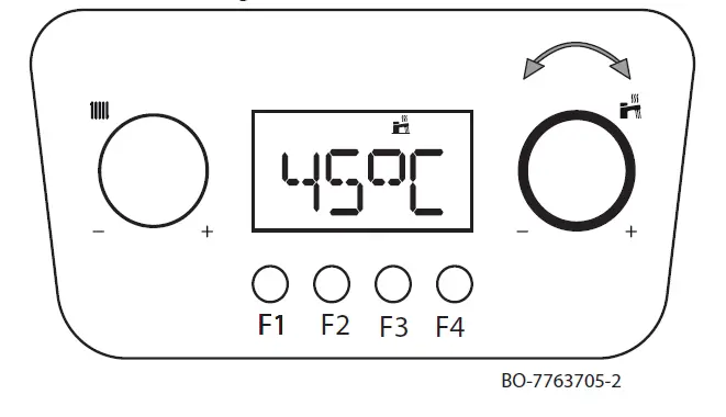
- Use the knob to adjust the domestic hot water temperature.
- Turn the knob anti-clockwise to reduce the temperature value.
- Turn the knob clockwise to increase the temperature value.
- Press the F4 key to confirm the value or wait a few seconds until the value is automatically saved
Shutdown
Switching off the heating and domestic hot water (DHW)
Heating mode can also be disabled by turning the until the word OFF appears on the display.
- Important
- When heating mode is re-enabled check, by turning the knob, that the comfort temperature is that requested.
- When heating mode is re-enabled check, by turning the
- Important
- Heating is disabled but the frost protection function remains activated.
- Domestic hot water mode can also be disabled by turning the knob anti-clockwise until the word OFF appears on the display.
- To switch the boiler off completely, switch off the power supply to the appliance and close the gas cock.
- Important
- In this condition, the boiler and the heating installation are not protected against frost.
Frost protection
It is a good idea to prevent the heating installation from draining completely, as changing the water can result in unnecessary and damaging limescale deposits from forming inside the boiler and heating elements. If the thermal installation is not intended to be used during the winter months and there is a risk of frost, we recommend mixing suitable antifreeze solutions designed for a specific purpose (e.g. propylene glycol,which contains limescale and corrosion inhibitors) into the water in the installation. The boiler’s electronic control system is equipped with an “antifreeze” function for the heating system. This function activates the boiler pump when the heating system flow temperature falls below 7 °C. If the water temperature reaches 4 °C, the burner is switched on, bringing the system water to a temperature of 10 °C. When this value is reached the burner switches off and the pump continues to operate for another 3 minutes.
Important
The frost protection function will not work if there is no power being supplied to the boiler or if the gas supply cock is closed.
Settings
Access to USER parameters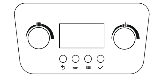
To display/modify the list of USER parameters, proceed as follows:
- press the
 keys simultaneously, the symbol
  on the menustarts to flash;
 - turn the Eknob until the
 appears. Press the
 key to confirm;
 - turn the Fknob until you reach the required setting. Press the key to confirm;
- modify the value of the parameter using knob;
- the Press thekey to confirm;
- Press the key to exit.
 on the menustarts to flash;
List of USER parameters
| Name | Description | Factory value | Mini mum | Maxi mum | Level |
| AP016 | CH operation 0: Off 1: On | 1 | – | – | User |
| AP017 | Domestic hot water (DHW) 0: Off 1: On | 1 | – | – | User |
| AP073 | Average external temperature [°C] when switching from summer/ winter mode (with outside sensor) | 22 | 10 | 30 | User |
| AP074 | Force summer mode (with outside sensor) 0: Auto according to AP073 1: Summer | 0 | – | – | User |
| DP004 | Anti-legionella function 0: Disabled 1: Weekly 2: Daily (only available with Room Unit) | 0 | – | – | User |
| DP070 | Domestic hot water temperature setpoint. In the case of operation with a calorifier tank and programming via room unit corresponding to the comfort setpoint [°C] | 60 | 35 | 60 | User |
| DP200 | DHW mode: 0: Domestic hot water programming (only available with Room Unit) 1: Manual (boiler with calorifier tank) – Preheating active (instanta neous boiler) 2: Antifreeze (boiler with calorifier tank) – No preheating (instantane ous boiler) | 2 | – | – | User |
| Name | Description | Factory value | Mini mum | Maxi mum | Level |
| CP060 | Required ambient temperature (°C) in the zone in the holiday/anti freeze period | 6 | 5 | 20 | User |
| CP070 | Maximum ambient setpoint temperature (°C) in reduced mode that enables switching to comfort mode with climate control (with outside sensor) | 16 | 5 | 30 | User |
| CP080 | Temperature (°C) set by SLEEP activity in the zone | 16 | 5 | 30 | User |
| CP081 | Temperature (°C) set by HOME activity in the zone | 20 | 5 | 30 | User |
| CP082 | Temperature (°C) set by AWAY activity in the zone | 6 | 5 | 30 | User |
| CP083 | Temperature (°C) set by MORNING activity in the zone | 21 | 5 | 30 | User |
| CP084 | Temperature (°C) set by EVENING activity in the zone | 22 | 5 | 30 | User |
| CP085 | Temperature (°C) set by CUSTOM activity in the zone | 20 | 5 | 30 | User |
| CP200 | Required ambient temperature (°C) for the zone in manual mode | 20 | 5 | 30 | User |
| CP250 | Correct the temperature measured by the room unit | 0 | -5 | +5 | User |
| CP320 | Zone operating mode 0: Scheduling 1: Manual 2: Off | 0 | – | – | User |
| CP510 | Temporary room setpoint per zone | 20 | 5 | 30 | User |
| CP550 | Fireplace mode 0: Disabled 1: Enabled | 0 | – | – | User |
| CP570 | Timer programme selected by User 0: Program 1 1: Program 2 2: Program 3 | 0 | – | – | User |
| DP060 | Timer programme selected for DHW 0: Program 1 1: Program 2 2: Program 3 | 0 | – | – | User |
| DP080 | Reduced temperature setpoint for the domestic hot water tank [°C] | 35 | 10 | 60 | User |
| DP337 | Domestic hot water temperature setpoint for the holiday period [°C] | 10 | 10 | 60 | User |
Important
The factory values of some parameters may differ according to the target market of the product
Maintenance
General
The boiler does not require any special maintenance. However, the boiler must be serviced annually in accordance with the Installation and Service
Manual and the relevant section of the Benchmark Service Record completed in order to maintain the warranty.
Note
Taking out a maintenance contract is recommended.
Caution
Maintenance operations must be performed by a qualified competent person.
Use only BAXI genuine spare parts.
The painted panels should be wiped with a damp cloth and then dried completely. DO NOT USE ABRASIVE CLEANING AGENTS.
Maintenance instructions
To ensure continued safety, functionality and efficiency, the boiler must be inspected annually by the installer/service engineer in order to ensure the performance of the product constant over time, we recommend having the boiler’s energy efficiency checked annually by a qualified technician. Accurate maintenance is always a reason for safety and savings in the management of the system.
Periodically check that the pressure shown on the display with the system cold is between 1 – 1.5 bar. If it is lower, act on the system filling tap. It is advisable that the opening of this tap is carried out very slowly in order to facilitate degassing.
Important
The boiler is equipped with a hydraulic pressure switch which does not allow the boiler to operate in case of low pressure. If frequent pressure drops should occur, call the installer/ service engineer
Filling the installation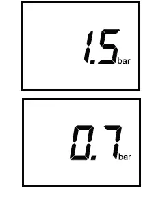
- If the water pressure is too low, the system must be re-pressurized.
- The normal operating water pressure is between 1 and 2 bar. If the pressure exceeds 3 bar the safety pressure valve will operate and a fault is indicated.
- Ensure that the temporary filling loop is disconnected. Contact your installer.
- It may be necessary to repressurize the system occasionally (when the water pressure falls below 0.7). A filling device (the filling loop) will be fitted on the system. This will be on the boiler itself, or on pipework near to the boiler. Seek advice from your installer.
Note
If the water pressure requires regular re-pressurising a fault or leak is indicated. Seek advice from your installer.
Filling loop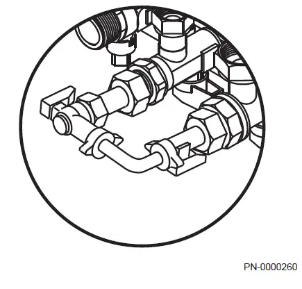
- Fully open one of the taps first, and then while watching the pressure gauge, carefully open the second tap.
Note
The system pressure is shown at all times on the display when there is power to the boiler. - When the figures on the display indicate between 1 and 1.5 bar turn both taps off.
- Disconnect the filling pipe from the taps (a small amount of water may be present) and remove it. Keep the pipe in a safe place for future use.
- If blanking caps are available fit them to the taps.
Note
Go to the “How to videos” section of the “Advice” page at www.baxi.co.uk for further details. - When the correct pressure is restored the boiler will reset automatically.
Venting the installation
It is essential to eliminate any air in the boiler, pipes or fittings because this can cause irritating noise during heating or the intake of water. To do this, proceed as follows: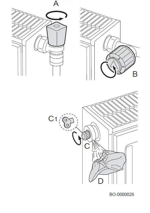
- Open the valves (A & B) of all the radiators connected to the central heating system.
- Set the ambient thermostat as high as possible.
- Wait for the radiators to heat up.
- Set the ambient thermostat as low as possible.
- Wait about 10 minutes until the radiators have cooled down.
- Vent the radiators. Start with the lower floors.
- Open the vent valve (C & C1) holding a cloth (D) against the valve.
- Wait until water comes out of the vent valve and then tighten it again.
- After venting, check that the system is still at sufficient pressure
Important
Take care as the water might still be hot.
Important
If the hydraulic pressure of the water in the central heating system is below 0.8 bar, it is advised to increase the pressure (the recommended hydraulic pressure is 1.0 – 1.5 bar).
Maintenance message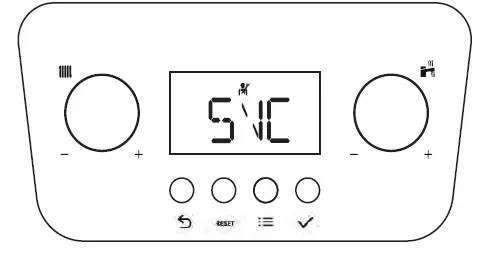
- The purpose of this function is to warn the user that the boiler requires maintenance
- When the letters SVC appear on the screen and the symbol
 flashes, the boiler requires maintenance. Contact your installer.
 flashes, the boiler requires maintenance. Contact your installer.
Troubleshooting
Temporary and permanent faults
The codes on the display indicate two types of fault: volatile and permanent. The first item shown on the display is a letter followed by a two-digit number. The letter indicates the type of fault: temporary (H) or permanent (E). The number indicates the group in which the fault that has occurred is classified according to its impact on safe and reliable operation. The second item shown flashes alternately with the first and consists of a two-digit number that indicates the type of fault which has occurred (see the following fault tables).
TEMPORARY FAULT (A/H.x.x.)
- A temporary fault is shown on the display by the letter “A” or “H” followed by a number (group). A temporary fault is a type of fault that does not cause a permanent stoppage of the boiler. It has the following characteristics:
- A: The appliance continues to operate. It disappears as soon as the cause has been resolved.
- H: Disappears when the error condition is removed, in some cases even after 10 minutes. PERMANENT FAULT (E.x.x)
- A permanent fault is shown on the display by the letter “E” followed by a number (group). Press the RESET button for one second. If faults are shown frequently, contact our authorised technical assistance centre.
- E: Stoppage, reset required..
Error codes
Tab.11 List of temporary faults
| DISPLAY | DESCRIPTION OF TEMPORARY FAULTS | CAUSE – Check/Solution An installer is required for most checks and solu tions. | |
| Group code | Specific code | ||
| H.00 | .42 | Pressure sensor open/faulty | SENSOR/CONNECTION PROBLEM Check the operation of the pressure sensor Check the sensor/PCB connection |
| H.01 | .00 | Temporary communication failure in the PCB | The error is resolved automatically |
|
H.01 |
.05 |
Maximum temperature difference value between flow and return reached. | INSUFFICIENT CIRCULATION Check the boiler/installation circulation Activate a manual venting cycle Check the installation pressure OTHER CAUSES Check the cleanliness of the exchanger Check the operation of the temperature sensors Check the temperature sensor connection |
|
H.01 |
.08 |
Flow temperature increase in heating mode too quick. | INSUFFICIENT CIRCULATION Check the boiler/installation circulation Activate a manual venting cycle Check the installation pressure Check the operation of the pump OTHER CAUSES Check the cleanliness of the exchanger Check the operation of the temperature sensors Check the temperature sensor connection |
| H.01 | .14 | Maximum flow or return temperature value reached. | INSUFFICIENT CIRCULATION Check the boiler/installation circulation Activate a manual venting cycle |
| DISPLAY | DESCRIPTION OF TEMPORARY FAULTS | CAUSE – Check/Solution An installer is required for most checks and solu tions. | |
| Group code | Specific code | ||
|
H.01 |
.18 |
No water circulation (temporary). | INSUFFICIENT CIRCULATION Check the installation pressure Activate a manual venting cycle Check the operation of the pump Check the boiler/installation circulation TEMPERATURE SENSOR ERROR Check the operation of the temperature sensors Check the temperature sensor connection |
|
H.01 |
.21 |
Flow temperature increase during domestic hot water operation too fast. | INSUFFICIENT CIRCULATION Check the installation pressure Activate a manual venting cycle Check the operation of the pump Check the boiler/installation circulation TEMPERATURE SENSOR ERROR Check the operation of the temperature sensors Check the connection of the temperature sensors |
| H.02 | .00 | Reset in progress. | It resolves itself |
| H.02 | .02 | Waiting for configuration settings to be entered (CN1,CN2). | CN1/CN2 CONFIGURATION MISSING Configure CN1/CN2 |
| H.02 | .03 | Configuration settings (CN1,CN2) not entered correc tly. | Check configuration CN1/CN2 Configure CN1/CN2 correctly |
| H.02 | .04 | PCB settings cannot be read. | MAIN PCB ERROR Configure CN1/CN2 Replace the main PCB |
| H.02 | .05 | Setting memory not compatible with the boiler PCB ty pe. | Contact the Service Network |
| H.02 | .07 | Low pressure in heating circuit (water filling required). | Check the installation pressure and restore Check the expansion vessel pressure Check for boiler/installation leaks |
| H.02 | .09 | Partial stoppage of the boiler (antifreeze function acti ve) | SIGNAL INDICATING BLOCKING INPUT Contact X15 open, check connected devices Parameter configuration error: Check AP001 |
| H.02 | .10 | Total stoppage of the boiler (antifreeze function not active) | SIGNAL INDICATING BLOCKING INPUT Contact X15 open, check connected devices Parameter configuration error: Check AP001 |
| H.02 | .70 | External unit heat recovery test failed | PCB accessory error SCB-09 Check the device connected to contact X9 |
| H.03 | .00 | No identification data for boiler safety device. | MAIN PCB ERROR Contact the Service Network |
|
H.03 |
.02 |
Temporary flame loss | ELECTRODE PROBLEM Check the electrode connection and wiring Check the condition of the electrode GAS SUPPLY Check the gas supply pressure Check the gas valve calibration FLUE GAS PIPES Check the pipes and the terminal |
| H.03 | .05 | Power supply voltage too low | Check the mains voltage |
|
H.03 |
.54 |
Temporary flame loss Shutdown due to the power supply voltage being too low | ELECTRODE PROBLEM Check the electrode electrical connections Check the condition of the electrode GAS SUPPLY Check the gas inlet pressure Check the gas valve calibration FLUE GAS EXHAUST PIPE Check the air intake and flue gas exhaust termi nal Check the power supply voltage |
| DISPLAY | DESCRIPTION OF PERMANENT FAULTS (RESET) | CAUSE – Check/Solution An installer is required for most checks and solu tions. | |
| Group code | Specific code | ||
| E.00 | .04 | Return temperature sensor disconnected | SENSOR/CONNECTION PROBLEM Check the operation of the temperature sensor Check the sensor/PCB connection |
| E.00 | .05 | Return temperature sensor short circuited | SENSOR/CONNECTION PROBLEM Check the operation of the sensor Check the sensor/PCB connection |
| E.00 | .16 | DHW tank temperature sensor not connected | SENSOR OPEN Check the operation of the sensor Check the sensor/PCB connection When removing a domestic hot water tank, set parameter DP150=1 |
| E.00 | .17 | DHW tank temperature sensor short-circuited | SENSOR CLOSED Check the operation of the sensor Check the sensor/PCB connection |
| E.00 | .20 | The flue gas temperature sensor is not connected or measured a temperature below the range | SENSOR OPEN Check the operation of the sensor Check the sensor/PCB connection |
| E.00 | .21 | The flue gas temperature sensor has short-circuited or measured a temperature above the range | SENSOR CLOSED Check the operation of the sensor Check the sensor/PCB connection |
|
E.01 |
.04 |
Flame loss detected five times in 24 hours | GAS SUPPLY Check the gas supply pressure Check the gas valve calibration ELECTRODE PROBLEM Check the electrode connection and wiring Check the condition of the electrode FLUE GAS PIPES Check the air intake and flue gas exhaust pipes EXCHANGER ON FLUE GAS SIDE BLOCKED Check the cleanliness of the exchanger MAINS VOLTAGE Check the power supply voltage |
| E.01 | .12 | Temperature measured by return sensor greater than flow temperature | SENSOR/CONNECTION PROBLEM Check that the sensors are positioned the correct way around Check that the flow sensor is in the correct posi tion Check the return temperature in the boiler Check the operation of the sensors |
|
E.01 |
.17 |
No water circulation (permanent) | INSUFFICIENT CIRCULATION Check the installation pressure Activate a manual venting cycle Check the operation of the pump Check the boiler/installation circulation SENSOR ERROR Check the operation of the temperature sensors Check the temperature sensor connection |
| E.01 | .20 | Maximum flue gas temperature reached | EXCHANGER ON FLUE GAS SIDE BLOCKED Check the cleanliness of the exchanger |
| E.02 | .13 | Total stoppage of the boiler (antifreeze function not active) | SIGNAL INDICATING BLOCKING INPUT Contact X15 open, check connected devices Parameter configuration error: Check setting AP001 |
| E.02 | .17 | Permanent communication failure in the PCB | MAIN PCB ERROR Check for any electromagnetic interference Contact the Service Network |
| DISPLAY | DESCRIPTION OF PERMANENT FAULTS (RESET) | CAUSE – Check/Solution An installer is required for most checks and solu tions. | |
| Group code | Specific code | ||
| E.02 | .35 | Critical safety device disconnected | COMMUNICATION FAULT Start the auto-detect function (parameter AD) Check the devices connected to contact X9 |
| E.02 | .39 | Minimum pressure not reached after 6 minutes of au tomatic filling | AUTOMATIC FILLING ERROR Check automatic filling is working |
| E.02 | .47 | Connection to external device unsuccessful | ELECTRICAL CONNECTION ERROR Start the auto-detect function (parameter AD)) Check the electrical connections of external devi ces. |
| E.04 | .01 | Flow temperature sensor short circuited | SENSOR/CONNECTION PROBLEM Check the sensor/PCB connection Check the operation of the sensor |
| E.04 | .02 | Flow temperature sensor disconnected | SENSOR/CONNECTION PROBLEM Check the sensor/PCB connection Check the operation of the sensor |
| E.04 | .03 | Maximum flow temperature exceeded or flow tempe rature sensor short circuited | INSUFFICIENT CIRCULATION Check the boiler/installation circulation Activate a manual venting cycle Check the operation of the sensors |
|
E.04 |
.08 |
Maximum safe temperature value reached | INSUFFICIENT CIRCULATION Check the pressure in the installation Switch on the manual degassing function Check that the pump is working Check the circulation in the boiler/installation OTHER POSSIBLE CAUSES Check the safety thermostat connection Check that the safety thermostat is working cor rectly |
|
E.04 |
.10 |
Burner failed to ignite after 4 attempts | GAS SUPPLY Check the gas supply pressure Check the gas valve electrical connection Check the gas valve calibration Check the operation of the gas valve ELECTRODE PROBLEM Check the electrode electrical connections Check the electrode condition OTHER CAUSES Check the operation of the fan Check the condition of the flue gas exhaust (bloc kages) |
| E.04 | .12 | Ignition failure for monitoring parasitic flame | Check the ground circuit Check the power supply voltage Check the electrode conditions |
| E.04 | .13 | Fan blade blocked or maximum rpm exceeded | FAN/PCB PROBLEM Check the PCB-fan connection Check the fan operation |
| E.04 | .17 | Fault in gas valve control circuit | MAIN PCB ERROR Check the electrical connections for the gas valve |
| E.04 | .18 | The flow temperature is below the minimum tempera ture or the flow temperature sensor is not connected | SENSOR/CONNECTION PROBLEM Check the sensor/PCB connection Check the operation of the sensor |
| E.04 | .23 | Communication internal stoppage | Switch the power supply off and on again and then RESET |
| E.04 | .29 | Communication internal stoppage | Switch the power supply off and on again and then RESET |
| E.04 | .254 | Fault in gas valve control circuit | MAIN PCB ERROR Check the electrical connections |
| DISPLAY | DESCRIPTION OF WARNINGS BEFORE A FAULT IS DETECTED | CAUSE – Check/Solution | |
| Group code | Specific code | ||
| A.00 | .28 | Solar temperature sensor is either removed or measures a temperature below range | Check the solar temperature sensor wiring. Re place the sensor if necessary. In case of removal of the solar tank, set the parameter DP150=1. |
| A.00 | .29 | Solar temperature sensor is either shorted or measures a temperature above range | Check the solar temperature sensor wiring. Re place the sensor if necessary. |
| A.00 | .34 | Outdoor temperature sensor expected but not detec ted | OUTDOOR SENSOR NOT DETECTED Enter the correct value of the parameter AP091 Connect the outdoor sensor Outdoor sensor is not connected correctly |
| A.02 | .06 | Low pressure in heating circuit | Check the installation pressure and restore Check the expansion vessel pressure Check for boiler/installation leaks |
| A.02 | .36 | Functional device disconnected | COMMUNICATION FAULT Start the auto-detect function (parameter AD) Check the devices connected to contact X9 |
| A.02 | .37 | Passive functional device disconnected | COMMUNICATION FAULT Start the auto-detect function (parameter AD) Check the devices connected to contact X9 |
| A.02 | .45 | Connection error | COMMUNICATION FAULT Start the auto-detect function (parameter AD)) |
| A.02 | .46 | Device priority error | COMMUNICATION FAULT Start the auto-detect function (parameter AD)) |
| A.02 | .48 | Unit function configuration error | ELECTRICAL CONNECTION ERROR Start the auto-detect function (parameter AD)) Check electrical connections of external devices |
| A.02 | .49 | Failed node initialisation | ELECTRICAL CONNECTION ERROR Start the auto-detect function (parameter AD)) Check electrical connections of external devices |
| A.02 | .54 | Open Therm bus power supply error | Check the devices connected to contact X17 – Terminal board M2 (7-8) |
| A.02 | .55 | Incorrect or missing serial number | Contact the Service Network |
| A.02 | .76 | Internal memory reserved for full customisation of set tings. No further changes can be made | Contact the Service Network |
Important
When connecting a Room Unit/Control Unit to the boiler, the code “254” is always shown in the event of a fault.. Read the fault code shown on the boiler display.
Fault finding
Tab.14 Problems and solutions
| Problem | Possible causes | Solution |
|
There is no domestic hot wa ter. | The boiler is not working. | Check that the boiler is being supplied with power. Check fuses and the switches. Check whether the gas isolation cock is properly open. If the property has a prepayment meter ensure it has sufficient credit. |
| The DHW function is switched off. | Activate the DHW mode. | |
| The water pressure is too low (< 0.5 bar). | Re-pressurise the system. | |
| Insufficient flow. | Flow must be at least 2 litres per minute. | |
|
The radiators are cold. | The temperature set point for the heating is too low. | Increase the value with the CH temperature knob or if a room thermostat is connected, increase the temperature on the room thermostat. |
| The heating mode is deactivated. | Activate the heating mode. | |
| The radiator valves are not open. | Open the valves of all radiators connected to the system. | |
| The boiler is not working. | Check that the boiler is being supplied with power. Check fuses and switches. Check whether the gas isolation cock is properly open. If the property has a prepayment meter ensure it has sufficient credit. | |
| The water pressure is too low (< 0.5 bar). | Re-pressurise the system. | |
|
The boiler is not working. | The temperature set point for the heating is too low. | Increase the value with the CH temperature knob or if a room thermostat is connected, increase the temperature on the room thermostat. |
| No demand for heating. | Ensure that timers & thermostats are calling for heat. | |
| No power supply. | Check that the boiler is being supplied with power. Check the fuses and switches. | |
| The water pressure is too low (< 0.5 bar). | Re-pressurise the system. | |
| The boiler is indicating an error. | Press the Reset button. Correct the error, if possible. | |
| The gas pressure is too low. | Check whether the gas isolation cock is fully open. Open the gas isolation cock. | |
| Condensate drain blocked. | Check drain, especially any external runs in freez ing temperatures. |
If the boiler is not working also check section “Operation checking procedure and basic fault identification” or contact your Installer.
Decommissioning
Decommissioning procedure
Caution
Only qualified persons are authorised to work on the appliance and system to decommission.
If your boiler needs to be decommissioned either temporarily or permanently the following should be performed:
- Switch off the boiler’s electrical connection.
- Close the gas isolation tap.
- Drain the central heating system. Seek the advice of your installer
Disposal
Disposal and recycling
The appliance is composed of multiple components made from various different materials, such as steel, copper, plastic, fibreglass, aluminium, rubber, etc..
These materials may be highly pollutant. This means that the boiler must be disposed of correctly by contacting staff at the nominated disposal facility or by taking it to a centre that is authorised to dispose of bulky waste (domestic appliances).
Warning
Removal and disposal of the boiler must be carried out by a qualified installer in accordance with local and national regulations.
Environmental
Energy saving
Tips on saving energy:
- Do not cover radiators. Do not hang curtains in front of radiators.
- Install reflective panels behind the radiators to prevent heat loss.
- Insulate the pipes in rooms that are not heated (cellars and lofts).
- Install loft insulation & double glazing.
- Use draught excluders where necessary.
- Upgrade any older boiler external controls.
- Turn down room thermostats by 1°.
- Turn off radiators in rooms not in use.
- Do not run hot (or cold) water pointlessly.
- Fit a water-saving shower head to save up to 40 % energy.
- Take showers rather than baths. A bath consumes twice as much water and energy.
Room thermostats and settings
Various models of room thermostat are available. The thermostat type and setting affect the total energy consumption.
A few tips:
- A modulating thermostat in combination with thermostatic radiator valves saves energy and offers considerable comfort. This combination gives you flexibility with the temperatures. Do not fit thermostatic radiator valves in the room in which the room thermostat is installed.
- Completely closing and opening thermostatic valve radiators causes undesirable temperature fluctuations. Open and close thermostatic valves in small steps.
- Lower the thermostat to around 20°C. This reduces heating costs and energy consumption.
- Lower the room thermostat temperature temporarily if opening windows to air the rooms.
- If you are using an ON/OFF type thermostat, reduce the water temperature value in summer (e.g. 60°C in summer and 80°C in winter).
- When setting an hourly programmable thermostat, consider days when you are absent or on holiday. Electricity production and energy savings reach their optimum level with a programmed and activated timer programme.
Warranty
General
To make sure your boiler warranty is activated and maintained, it is essential that the:
- Benchmark checklist is completed by your installer
- Warranty is registered within 30 days
- Boiler has an annual service
Important
Please note that failure to adhere to terms and conditions will invalidate your warranty
Standard warranty terms and conditions
Warranty registration, service & repair
For full terms and conditions, visit www.baxi.co.uk/terms.
Benchmark checklist
The Benchmark Checklist will be completed by your installer and records that the boiler has been installed and commissioned correctly. It can be found at the back of the installation and service manual and should be kept in a safe place for the life of the boiler. We will check that the Benchmark Checklist has been completed on an in-warranty visit.
Ways to register your warranty
If your boiler is eligible for an extended warranty, your installer may register the product on your behalf and provide you with the relevant documentation. Please check with your installer.
Should this not be the case, you can register your warranty online at www.baxi.co.uk/registration
Annual service
A service must be completed every 12 months from the date of installation to maintain your warranty.
This service must be completed by one of the following:
- A Gas Safe registered installer/engineer
- Baxi Customer Support; call us 0344 871 1545
Please make sure that your engineer has logged the service information at the back of the installation and service manual. You will be asked for your service history on any in-warranty repair visit.
If you experience a problem with your boiler
For any in or out of warranty repair, Baxi Customer Support is on hand to help you. Call our award-winning team to arrange for one of our nationwide team of Gas Safe registered engineers to visit.
If your product is in warranty, everything is free of charge, subject to our warranty terms and conditions. If it is out of warranty, we can still help and offer a range of options you can choose from to suit your needs.
Contact Baxi Customer Support 0344 871 1545
- Opening hours
- Monday – Friday, 8.00am – 6.00pm
- Weekends and Bank Holidays, 8.30am – 2.00pm
- Please note calls may be recorded for training and monitoring purposes.
When contacting Baxi Customer Support, please have the following information to hand:
- Boiler serial number.
- Proof of purchase if you do not have the boiler serial number
Please note that for in-warranty repairs, our engineers will ask to see your service history record, completed Benchmark Checklist and details of your installer. These can all be found in the Installation and Service manual
Appendix
Product fiche – Combination boilers
| 424 | 430 | 424 LPG | 430 LPG | ||
| Space heating – Temperature application | Medium | Medium | Medium | Medium | |
| Water heating – Declared load profile | XL | XL | XL | XL | |
| Seasonal space heating energy efficiency class | |||||
| Water heating energy efficiency class | |||||
| Rated heat output (Prated or Psup) | kW | 20 | 20 | 20 | 20 |
| Space heating – Annual energy consumption | GJ | 62 | 62 | 62 | 62 |
| Water heating – Annual energy consumption | kWh(1) GJ(2) | 39 17 | 42 17 | 39 17 | 42 17 |
| Seasonal space heating energy efficiency | % | 93 | 93 | 93 | 93 |
| Water heating energy efficiency | % | 88 | 89 | 88 | 89 |
| Sound power level LWA indoors | dB | 50 | 49 | 50 | 49 |
| (1) Electricity (2) Fuel | |||||
See
For specific precautions about assembling, installing and maintaining: Safety, page 5
Package fiche – boilers
Package fiche for boilers indicating the space heating energy efficiency of the package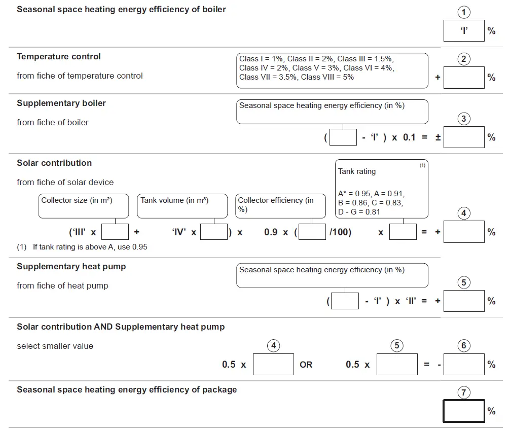
The energy efficiency of the package of products provided for in this fiche may not correspond to its actual energy efficiency once installed in a building, as this efficiency is influenced by further factors such as heat loss in the distribution system and the dimensioning of the products in relation to building size and characteristics
- The value of the seasonal space heating energy efficiency of the preferential space heater, expressed in %.
- The factor for weighting the heat output of preferential and supplementary heaters of a package as set out in the following table.
- The value of the mathematical expression: 294/(11 · Prated), whereby ‘Prated’ is related to the preferential space heater.
- The value of the mathematical expression 115/(11 · Prated), whereby ‘Prated’ is related to the preferential space heater
Weighting of boilers
| Psup / (Prated + Psup)(1)(2) | II, package without hot water storage tank | II, package with hot water storage tank |
| 0 | 0 | 0 |
| 0.1 | 0.3 | 0.37 |
| 0.2 | 0.55 | 0.70 |
| 0.3 | 0.75 | 0.85 |
| 0.4 | 0.85 | 0.94 |
| 0.5 | 0.95 | 0.98 |
| 0.6 | 0.98 | 1.00 |
| ≥ 0.7 | 1.00 | 1.00 |
| (1) The intermediate values are calculated by linear interpolation between the two adjacent values. (2) Prated is related to the preferential space heater or combination heater. | ||
Package efficiency
| Baxi Combi | 424 | 430 | 424 LPG | 430 LPG | |
| Temperature control X | % | ||||
| Temperature control Y | % |
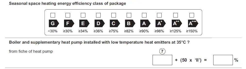
Package fiche – Combination heaters (boilers or heat pumps)
Package fiche for combination heaters (boilers or heat pumps) indicating the water heating energy efficiency of thepackage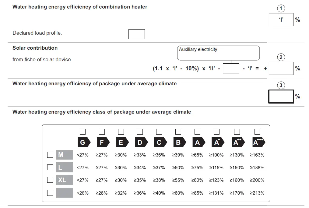

The energy effi ciency of the package of products provided for in this fi che may not correspond to its actual energy effi ciency once installed in a building, as this effi ciency is infl uenced by further factors such as heat loss in the distribution system and the dimensioning of the products in relation to building size and characteristics
- The value of the water heating energy efficiency of the combination heater, expressed in %.
- The value of the mathematical expression (220 · Qref)/Qnonsol, where Qref is taken from Regulation EU 811/2013, Annex VII Table 15 and Qnonsol from the product fiche of the solar device for the declared load profile M, L, XL or XXL of the combination heater.
- The value of the mathematical expression (Qaux · 2,5)/(220 · Qref), expressed in %, where Qaux is taken from the product fiche of the solar device and Qref from Regulation EU 811/2013, Annex VII Table 15 for the declared load profile M, L, XL or XXL.
Copyright
All technical and technological information contained in these technical instructions, as well as any drawings and technical descriptions supplied, remain our property and shall not be multiplied without our prior consent in writing. Subject to alterations.
Baxi Customer Support
- 0344 871 1545
- Opening hours
- Monday – Friday, 8.00 am-6.00 pm
- Weekends and Bank Holidays, 8.30 am-2.00 pm
- Please note calls may be recorded for training and monitoring purposes
baxi.co.uk
Register now to activate your warranty:
www.baxi.co.uk/registration
For the warranty to be maintained, please make sure…
- Benchmark checklist is completed
- Warranty is registered within 30 days
- The boiler has an annual service
For full terms and conditions, visit www.baxi.co.uk/terms. Failure to adhere to terms and conditions will void your manufacturer’s warranty
Baxi Brooks House, Coventry Road, Warwick, CV34 4LL
Please ensure the boiler is installed in accordance with these installation instructions and that you adhere to the Building Regulations.
e&oe
All descriptions and illustrations provided in this document have been carefully prepared but we reserve the right to make changes and improvements in our products which may affect the accuracy of the information contained in this leaflet. All goods are sold subject to our standard Conditions of Sale which are available on request.


