![]()
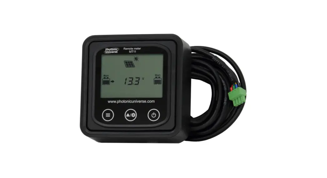
REMOTE METER
Model: MT11
INSTRUCTION MANUAL 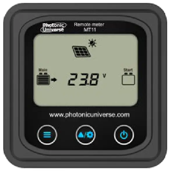 For use with DM series dual battery MPPT solar charge controllers
Important Safety Instructions
SAVE THESE INSTRUCTIONS:
This manual contains important safety, installation and operating instruction for the remote meter.
General safety information
- Please inspect the MT11 thoroughly after it is delivered. If there is any damage, document this with photos and contact the shipping company or seller for assistance.
- Please read this manual carefully before installing the product and pay close attention to the safety information.
- Keep the MT11 away from rain, dust, vibrations, corrosive gas and intense electromagnetic interference.
- Do not allow water to enter the remote meter.
- There are no user serviceable parts inside the remote meter. Do not disassemble or attempt to repair it.
- The MT11 is only compatible with DM series charge controllers.
Please confirm before purchase and installation.
Overview
The MT11 remote meter is an accessory which is compatible with the DuoRacer (DM series) MPPT solar controller. It can monitor the running data and working status of the controller, set the battery type and temperature units, and reset the generated energy counter.
Features:
- Automatically identify and display the type, model and relevant parameter data of compatible controllers.
- Real-time display of the operational data and working status of the connected device in digital, graphical and textual forms by a largescreen multifunctional LCD.
- Three touch buttons are quick and easy to operate.
- No need for external power supply. The connected charge controller supplies the power for MT11.
- The meter can browse the controller’s parameters, set the battery type and temperature unit, and reset the generated energy counter.
- Real-time display of fault information of the connected devices.
- Long communication distance via RS485.
Product Components
- Remote meter MT11
- 5m communication cable (Model: CC-RS485-RS485-3.81-4P-500)
- Optional Mounting Frame
Installation
4.1 Mounting Frame (optional accessory, included)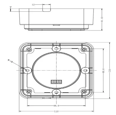
| Mechanical parameter | Measurement |
| Overall dimensions | 114 x 114 x 44.41mm |
| Mounting dimensions | 88.6 x 88.6mm |
| Terminal | Φ5 |
4.2 Wall installation steps
Step 1: Mark and drill screw holes to match the mounting dimensions of the base, and insert the plastic expansion bolts.
Step 2: Use four PA4.2×32 self-tapping screws to fix the frame to the wall.
Step 3: Remove the decorative shell.
Step 4: Use four M4×8 pan head screws to mount the MT11 screen onto the frame.
Step 5: Install the decorative shell over the screen. 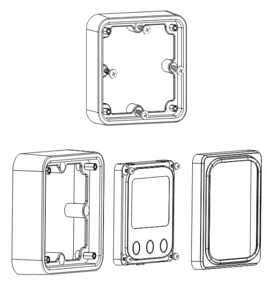
4.3 Surface mounting steps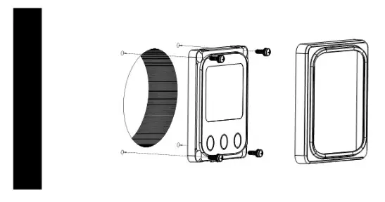
Step 1: Mark and cut an appropriately-sized hole in the surface for the cable and rear of the screen.
Step 2: Mark and drill screw holes based on the mounting dimensions.
Step 3: Remove the decorative shell.
Step 4: Use four M4×8 cross recessed pan head screws with M4 nuts to mount the MT11 screen onto the surface.
Step 5: Install the decorative shell.
NOTE: Consider the plugging/unplugging space and the length of the cable during installation to ensure the cable will fit.
Product Features
5.1 Front View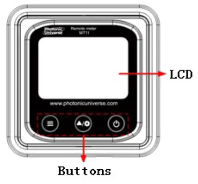 LCD display screen
Remote meter operation interface. Refer to chapter 6 for details of display and operation.
Buttons
The meter buttons include two function buttons and one switch button.
| Press the button | 1. PV array parameters 2. Storage battery parameters 3. Browse the starter battery parameters automatically ( | |
 | Press the button | 1. Browse the PV array parameters 2. Browse the storage battery parameters 3. Browse the starter battery parameters Temperature units/Battery type |
| Press the buttonand hold for 5s | ||
| Press the button | Turn the meter ON Turn the meter OFF | |
| Press the button and hold for 5s |
5.2 Rear View 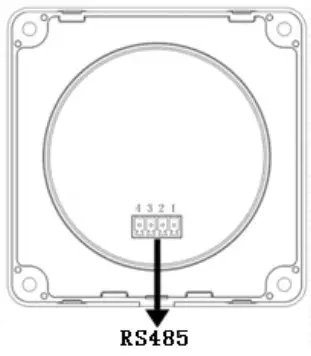
RS485 communication port
Used to connect to the solar controller which, provides power and data to the MT11.
Communication cable models
CC-RS485-RS485-3.81-4P-500 (Included, 5m length)
CC-RS485-RS485-3.81-4P-1000 (Optional, 10m length)
CC-RS485-RS485-3.81-4P-2000 (Optional, 20m length)
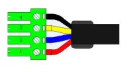
Pins definition
| PIN | Definition |
| 1 | DC5V |
| 2 | RS-485-B |
| 3 | RS-485-A |
| 4 | GND |
Display and Operation
6.1 LCD display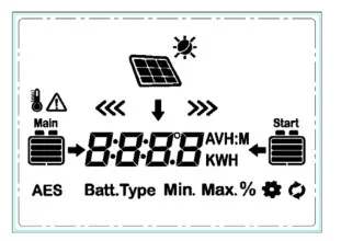
| Icon | Instruction | Icon | Instruction |
| BATT1 battery capacity level ① 0~12% | BATT2 battery capacity level ① 0~12% | ||
| BATT1 battery capacity level ① 13%~35% | BATT2 battery capacity level ① 13%~35% | ||
| BATT1 battery capacity level ① 36%~61% |  | BATT2 battery capacity level ① 36%~61% | |
| BATT1 battery capacity level ① 62%~86% | BATT2 battery capacity level ① 62%~86% | ||
| BATT1 battery capacity level ① 87%~100% |  | BATT2 battery capacity level ① 87%~100% | |
| Day | PV array | ||
| Night | BATT1 charging icon | ||
| Display the parameters of the PV array | BATT2 charging icon | ||
| Display the parameters of BATT1 | BATT1 temperature parameters | ||
| Display the parameters of BATT2 | AES | AES signal icon | |
| Setting icon | Batt.Type | Battery type icon | |
| Auto global view sign | Min. | Minimum voltage icon | |
| Fault icon | Max. | Maximum voltage icon |
① Battery power capacity is calculated by a linear relationship between the disconnect voltage and float charging voltage.
6.2 Auto global view mode
Operation:
Step 1: Press the ![]() button,
button,![]() will appear.
will appear.
Step 2: Press the![]() button, select the
button, select the![]() . The display will now automatically loop through all parameters.
. The display will now automatically loop through all parameters.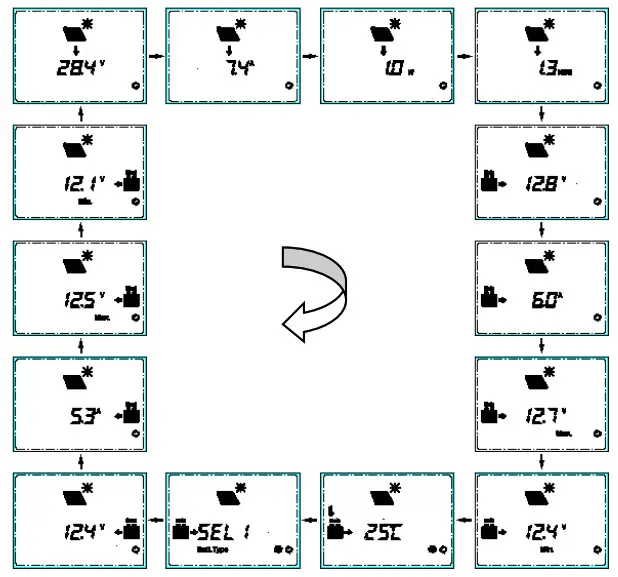
Display Loop: PV voltage → PV current → PV power→ Battery power → BATT1 voltage → BATT1 current → Max. BATT1 voltage → Min.BATT1 voltage → BATT1
temperature → BATT1 battery type → BATT2 voltage → BATT2 current → Max. BATT1 voltage → Min.BATT2 voltage → PV voltage
6.3 Temperature units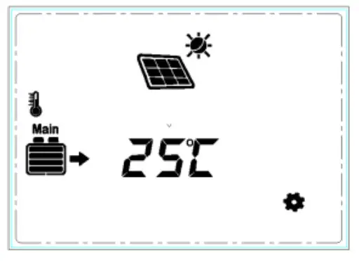
Operation:
Step 1: Press the ![]() button under the battery temperature interface.
button under the battery temperature interface.
Step 2: Press the ![]() button to select the temperature unit.
button to select the temperature unit.
Step 3: Press the![]() button to set successfully.
button to set successfully.
6.4 Clear the generated energy 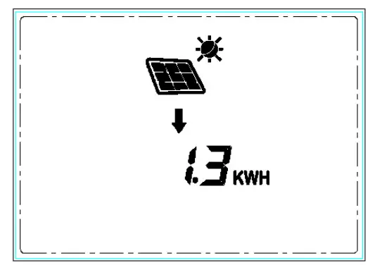
Press the![]() and button
and button![]() and hold for 5s to clear the generated energy.
and hold for 5s to clear the generated energy.
6.5 Battery type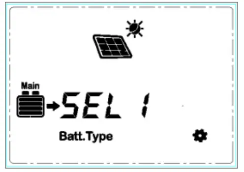
1)Operation:
Step 1: Press the ![]() button and hold for 5s under the battery type interface.
button and hold for 5s under the battery type interface.
Step 2: Press the![]() button when the battery type interface is flashing.
button when the battery type interface is flashing.
Step 3: Press the![]() button to confirm the battery type.
button to confirm the battery type.
2) Battery type
 | BATT1 12V Sealed | BATT1 24V Sealed | |
| BATT1 12V Gel | BATT1 24V Gel | ||
| BATT1 12V Flooded | BATT1 24V Flooded | ||
| LiFePO4 (4S) |  | LiFePO4 (8S) | |
| Li-NiCoMn (3S) | Li-NiCoMn (6S) | ||
 | User |
NOTE: The battery voltage is set as default and not changeable when selecting the default battery type. Please change to “User” battery type before adjusting the battery voltage. Set the voltage of the “User” battery type via PC software only.
1) Lead-acid Battery Control Voltage Parameters
The parameters below are for a 12V system at 25 ºC. Please double the values in a 24V system.
| Battery type /Voltage parameter | Sealed | Gel | Flooded | User |
| Over Voltage Disconnect Voltage | 16.0V | 16.0V | 16.0V | 9-17V |
| Charging Limit Voltage | 15.0V | 15.0V | 15.0V | 9-17V |
| Over Voltage Reconnect Voltage | 15.0V | 15.0V | 15.0V | 9-17V |
| Equalize Charging Voltage | 14.6V | → | 14.8V | 9-17V |
| Boost Charging Voltage | 14.4V | 14.2V | 14.6V | 9-17V |
| Float Charging Voltage | 13.8V | 13.8V | 13.8V | 9-17V |
| Boost Reconnect Charging Voltage | 13.2V | 13.2V | 13.2V | 9-17V |
| Low Voltage Reconnect Voltage | 12.6V | 12.6V | 12.6V | 9-17V |
| Under Voltage Warning Reconnect Voltage | 12.2V | 12.2V | 12.2V | 9-17V |
| Under Volt. Warning Voltage | 12.0V | 12.0V | 12.0V | 9-17V |
| Low Volt. Disconnect Voltage | 11.1V | 11.1V | 11.1V | 9-17V |
| Discharging Limit Voltage | 10.6V | 10.6V | 10.6V | 9-17V |
| Equalize Duration (min.) | 120 | → | 120 | 0-180 |
| Boost Duration (min.) | 120 | 120 | 120 | 10-180 |
NOTE:
- When the battery type is sealed, gel, or flooded, the adjustable range of equalize duration is 0 to 180min, and boost duration is 10 to 180min.
- The following rules must be observed when modifying the value of the parameters in User battery type (factory default value is the same as sealed type):
A. Over Voltage Disconnect Voltage > Charging Limit Voltage ≥ Equalize Charging Voltage ≥ Boost Charging Voltage ≥ Float Charging Voltage >
Boost Reconnect Charging Voltage.
B. Over Voltage Disconnect Voltage > Over Voltage Reconnect Voltage C. Low Voltage Reconnect Voltage > Low Voltage Disconnect Voltage ≥
Discharging Limit Voltage.
D. Under Voltage Warning Reconnect Voltage > Under Voltage Warning Voltage ≥ Discharging Limit Voltage.
Boost Reconnect Charging voltage > Low Voltage Disconnect Voltage.
2) Lithium Battery Control Voltage Parameters
The parameters below are for a 12V system at 25 ºC; please double the values in a 24V system.
| Battery type/ Voltage parameter | LiFePO4 (4S) | Li-NiCoMn (3S) | User |
| Over Voltage Disconnect Voltage | 15.6V | 13.5V | 9-17V |
| Charging Limit Voltage | 14.6V | 12.6V | 9-17V |
| Over Voltage Reconnect Voltage | 14.5V | 12.5V | 9-17V |
| Equalize Charging Voltage | 14.5V | 12.5V | 9-17V |
| Boost Charging Voltage | 14.5V | 12.5V | 9-17V |
| Float Charging Voltage | 13.8V | 12.2V | 9-17V |
| Boost Reconnect Charging Voltage | 13.2V | 12.1V | 9-17V |
| Low Voltage Reconnect Voltage | 12.4V | 10.5V | 9-17V |
| Under Voltage Warning Reconnect Voltage | 12.5V | 11.0V | 9-17V |
| Under Volt. Warning Voltage | 12.0V | 10.5V | 9-17V |
| Low Volt. Disconnect Voltage | 11.0V | 9.3V | 9-17V |
| Discharging Limit Voltage | 10.8V | 9.3V | 9-17V |
A. Over Voltage Disconnect Voltage > Over charging protection voltage (Protection Circuit Modules (BMS))+0.2V;
B. Over Voltage Disconnect Voltage > Over Voltage Reconnect Voltage = Charging Limit Voltage ≥ Equalize Charging Voltage = Boost Charging Voltage ≥ Float Charging Voltage > Boost Reconnect Charging Voltage;
C. Low Voltage Reconnect Voltage > Low Voltage Disconnect Voltage ≥ Discharging Limit Voltage;
D. Under Voltage Warning Reconnect Voltage > Under Voltage Warning Voltage ≥ Discharging Limit Voltage;
E. Boost Reconnect Charging voltage > Low Voltage Reconnect Voltage;
F. Low Voltage Disconnect Voltage ≥ Over-discharging protection voltage (BMS)+0.2V.![]() WARNING: Please refer to the voltage parameters of the BMS when adjusting the lithium battery voltage parameters.
WARNING: Please refer to the voltage parameters of the BMS when adjusting the lithium battery voltage parameters.![]() WARNING: The accuracy of BMS must be at least 0.2V. If the deviation is higher than 0.2V, the manufacturer will assume no liability for any system malfunction caused by this.
WARNING: The accuracy of BMS must be at least 0.2V. If the deviation is higher than 0.2V, the manufacturer will assume no liability for any system malfunction caused by this.
6.6 Fault indication
| Fault | LCD | Instruction |
| BATT1 overvoltage | Battery level shows full, battery frame blink, fault icon blink. | |
| BATT1 over- discharged |  | Battery level shows empty, battery frame blink, fault icon blink. |
| BATT1 over temperature | 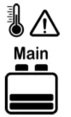 | Battery level shows current capacity, battery frame blink, fault icon blink, the temperature icon blink, the temperature value blink, the temperature unit blink. |
| BATT1 system voltage error® | 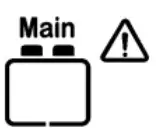 | Battery level shows empty, battery frame blink. |
① No alarm for system voltage fault when using Lithium batteries.
Technical Specifications
| Compatible models | DM series (DM1024/DM2024/DM3024) |
| Self-consumption (Power on) | 13mA/5Vdc |
| Self-consumption (Power off) | 4mA/5Vdc |
| Communication protocol | RS485 |
| Communication port | 3.81-4P |
| RS485 cable | CC-RS485-RS485-3.81-4P-500 (5m) |
| Environmental temperature | -20ºC~+70ºC |
| Storage temperature range | -20ºC~+70ºC |
| Enclosure | IP20 |
| Screen unit dimensions | 98.4×98.4mm |
| Frame dimensions | 114×114mm |
| Weight | 0.11kg |
Manual is subject to change without prior notice. Version number: 2.7
Photonic Universe Ltd
Tel: + 44 (0) 20 3150 11 11
Fax: + 44 (0) 20 3150 12 12
E-mail:[email protected]
Website: http://www.photonicuniverse.com


