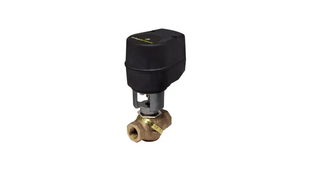
![]() AT000 2-Way 1-2 Inch Globe Valve
AT000 2-Way 1-2 Inch Globe Valve
Instruction Manual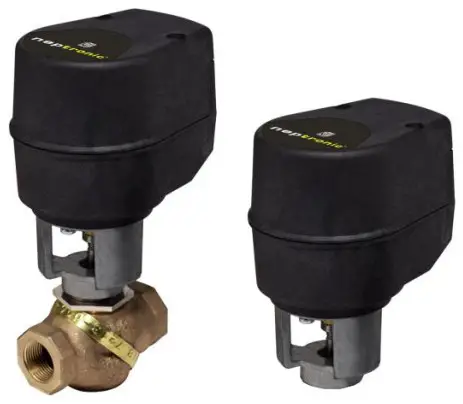
AT000/AT020/AT060/AT080
Feature:
- Variable running time.
- Manuel override.
- Maintenance free.
- Fail safe by Enerdrive System¹
(on models 060 & 080). - Auxiliary switches.
(on models 020 & 080).
| Technical Data | AT000 | AT020 | AT060 | AT080 |
| Auxiliary switches | No | Yes(2) | No | Yes(2) |
| Feedback | No | No | No | No |
| Fail safe – Enerdrive | No | Yes | ||
| Power consumption | 6 VA | 20VA Peak. 6VA | ||
| Control signal | 3 wire / 2 position. 3 wire / 3 point floating | 2 wire / 2 position. 4 wire / 3 point floating | ||
| Running time | 60 sec force dependant | |||
| Force | 100 lb. [450 N] at rated voltage | |||
| Power supply | 22 to 26 VAC or 28 to 32 VDC | |||
| Electrical connection | 18 AWG [0.8 mm²] minimum | |||
| Inlet bushing | 2 inlet bushing of 5/8 in [15.9 mm] & 7/8 in [22.2 mm] | |||
| Maximum Stroke | 0.5 in [12.7mm] | |||
| Direction | Reversible. normally open or normally close (factory set with normally close direction) | |||
| Ambient temperature | 0°F to +122°F [-18°C to +50°C] | |||
| Storage temperature | -22°F to +122°F [-30°C to +50°C] | |||
| Relative Humidity | 5 to 95 % non condensing. | |||
| Weight | 2 lbs. [0.9 kg] | |||
| Warning: Do not use automatic screw driver on manual override | ||||
Dimensions
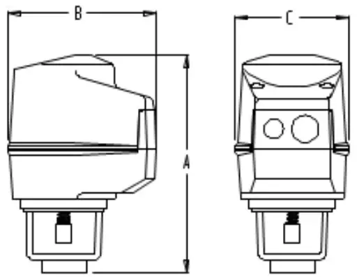
| Dimension | Inches | Metric (mm) |
| A | 5.93 | 150.6 |
| B | 4.8 | 121.9 |
| C | 3.6 | 91.4 |
Caution
We strongly recommend that all neptronic® products be wired to a separate transformer and that transformer shall service only neptronic® products. This precaution will prevent interference with, and/or possible damage to incompatible equipment.
When multiple actuators are wired on a single transformer, polarity must be observed. Long wiring runs create voltage drop which may affect the actuator performance.
¹ Enerdrive Fail-Safe System: US Patent #5,278,454
European Patent #0647366![]()
Mechanical installation
Mounting of the actuator on valve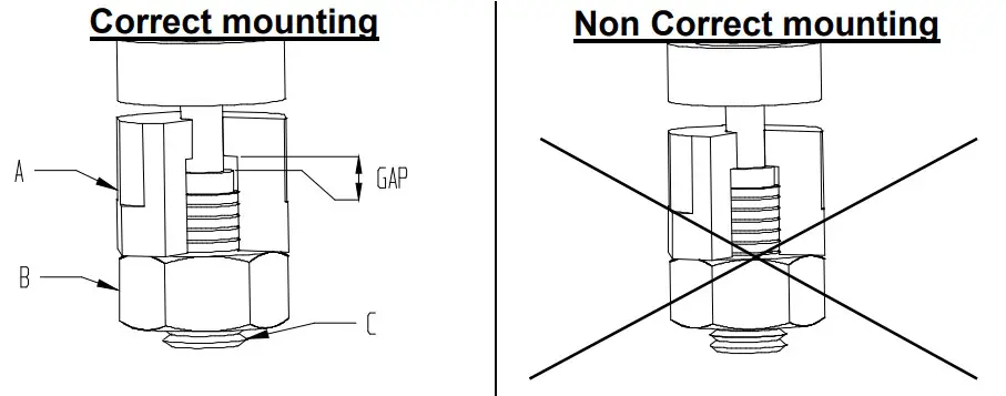
- Screw completely the valve shaft (C) unto the coupling of the actuator (A).
- Unscrew the coupling (A) for ½ of turn in order to leave a functional play.
- Screw the counter nut (B).
Warning:
Do not over tight coupling of the actuator on the shaft of the valve.
Mounting of the actuated valve on system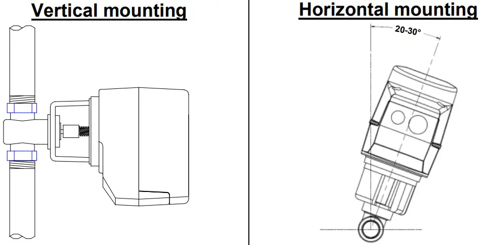
- Pay attention to system particularity; be sure that the expansions, contractions of the system and its medium as well as operating pressures are within the tolerances.
- When plumbing, the motorized valve should be situated in an easily accessible place and sufficient space should be allowed for the removal of the actuator.
- To prevent moisture from collecting in the motor casing,install the motorized valve such that the actuator is superior to the valve, at 20-30º / at vertical. Avoid mounting the valve so that the valve stem is below horizontal.
Wiring Diagrams
Models AT000 & 020
3 wire/2 position (ON-OFF)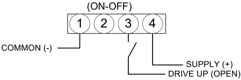 3 wire/3 point floating
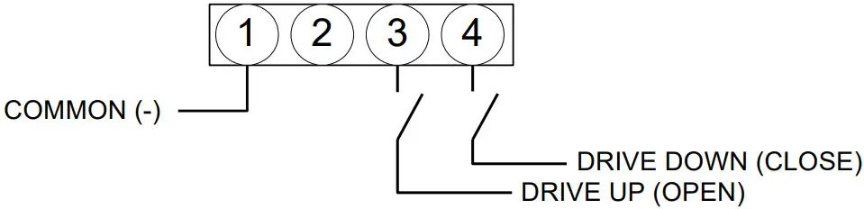
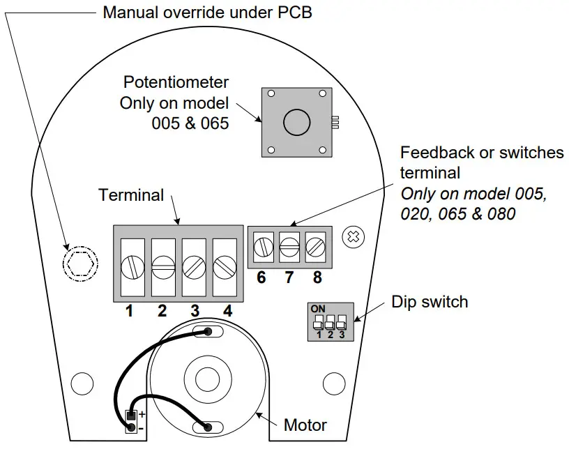
Models AT060 & 080
2 wire/2 position (ON-OFF)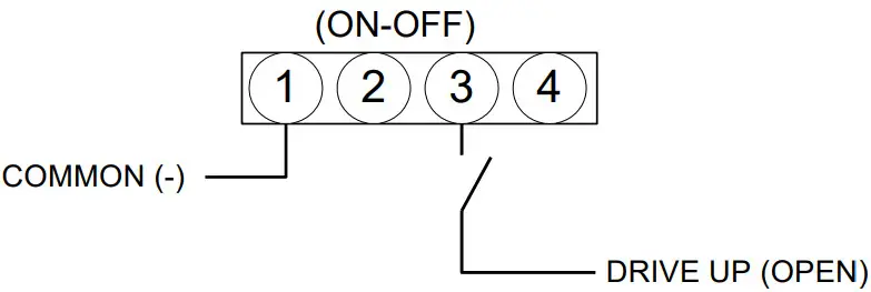 4 wire/3 point floating
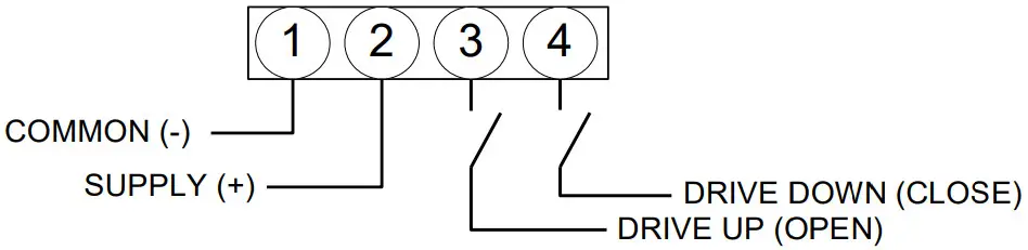 PC Board
 Dip switch settings
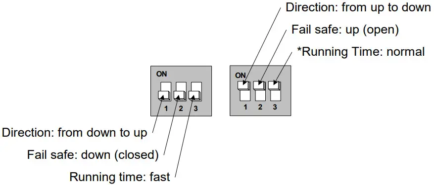 *On AT model:
When switch #3 is “ON”, the running time will be 60 sec.
![]() AT-220119
AT-220119


