![]()
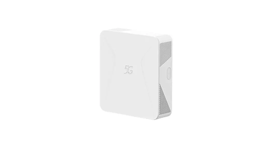
RXAM JD1 Access Point
User Manual
Federal Communication Commission Interference Statement
This equipment has been tested and found to comply with the limits for a Class B digital device, pursuant to Part 15 of the FCC Rules. These limits are designed to provide reasonable protection against harmful interference in a residential installation. This equipment generates, uses and can radiate radio frequency energy and, if not installed and used in accordance with the instructions, may cause harmful interference to radio communications. However, there is no guarantee that interference will not occur in a particular installation. If this equipment does cause harmful interference to radio or television reception, which can be determined by turning the equipment off and on, the user is encouraged to try to correct the interference by one of the following measures:
- Reorient or relocate the receiving antenna.
- Increase the separation between the equipment and receiver.
- Connect the equipment into an outlet on a circuit different from that to which the receiver is connected.
- Consult the dealer or an experienced radio/TV technician for help.
This device complies with Part 15 of the FCC Rules. Operation is subject to the following two conditions: (1) This device may not cause harmful interference, and (2) this device must accept any interference received, including interference that may cause undesired operation.
This device is going to be operated in the 5.15-5.25GHz frequency range, it is restricted to use in indoor environments only.
This device is restricted for indoor use. Professional installation is required.
IMPORTANT NOTE:
FCC Radiation Exposure Statement: This equipment complies with FCC radiation exposure limits set forth for an uncontrolled environment. This equipment should be installed and operated with a minimum distance of 24 cm between the radiator & your body.
FCC Caution: Any changes or modifications not expressly approved by the party responsible for compliance could void the user’s authority to operate this equipment.
INTRODUCTION
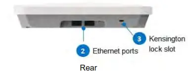
1.1 Product Appearance and layout
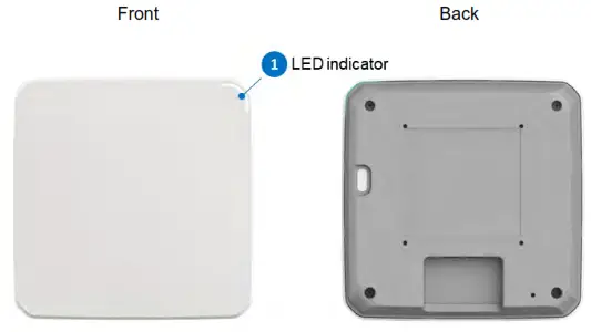
1.2 LED Light Guide
The LED indicator is located on the top right corner of the Access Point and displays the operational status of the device. Refer to the guide below for LED status descriptions:
| LED Status | Description |
| No light | Device is unpowered or LED indicator is disabled. |
| Amber | An abnormality has occurred |
| White | Device is ready and fully operational |
Mounting the Access Point
This section describes how to mount the Access Point.
2.1 Accessories for Installation
Main bracket x 1
Adapter brackets x 2
Wall screws x 3 (8X25)
Wall anchors x 3 (BH(2#)M3-24×25 TP—A(6.3, 1.9))
M4 screws x 4 (PH+SW+WM4-0.7×8 W=8 CR3/Zn)
M3 screws x 4 (PH+SW+WM3-0.5×6 W=8 Ni)
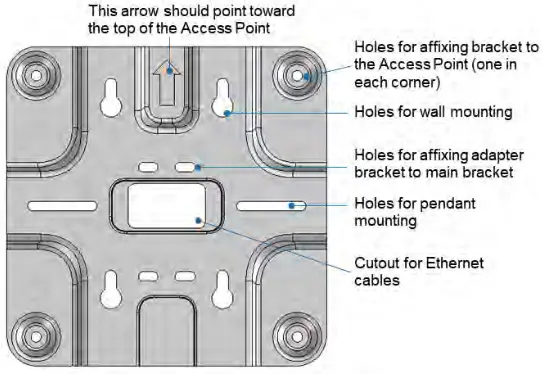
2.2 Main Bracket
The main bracket enables the Access Point to be installed onto ceilings, walls, or pendant mounted. The features of the bracket are listed below:
2.3 Ceiling Mounting
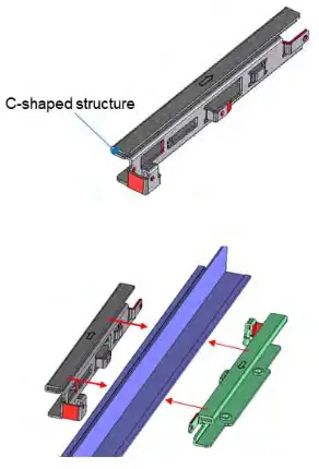
Refer to the steps below to mount the Access Point onto T-bar ceilings.
- Use the C-shaped structure to attach the two adapter brackets to either side of the T-bar, making sure that the arrows on the brackets are facing opposite directions.
 After the adapter brackets are affixed onto the T-bar, slide the brackets in the direction of the arrows on the brackets until they are securely attached to each other. Refer to the images below for how the adapter brackets should fit.
 Section A of the left bracket goes into Section B of the right bracket
 Section C of the right bracket goes into Section D of the left bracket
- Align the screw holes on the adapter brackets with the holes on the main bracket (refer to section 2.2), then use four M3 screws to screw the main bracket to the adapter brackets.

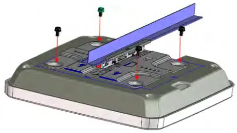
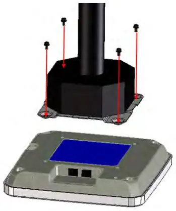
4. Align the screw holes on the main bracket with the corresponding holes on the back of the Access point, then use four M4 screws to attach the main bracket to the Access Point.
Note: Make sure the arrow on the main bracket is aligned so that it is pointing toward the top side of the Access Point.
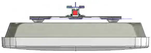
5. Once the aforementioned steps are complete, the side-view of the completed setup should look like the image below:
 After the adapter brackets are affixed onto the T-bar, slide the brackets in the direction of the arrows on the brackets until they are securely attached to each other. Refer to the images below for how the adapter brackets should fit.
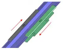 Section A of the left bracket goes into Section B of the right bracket
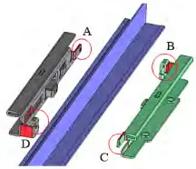 Section C of the right bracket goes into Section D of the left bracket
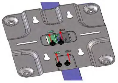
2.4 Pendant Mount
Refer to the steps below to mount the Access Point to a pendant mount.
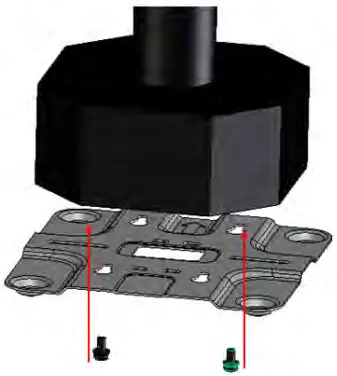
- Align the pendant mount screw holes on the main bracket with the holes on the pendant mount.
- Use the pendant mount screws (M4 screws; length: 12.7 mm; material: normal aluminum, non-surface treated) to securely affix the main bracket to the pendant mount.

3. Align the screw holes on the main bracket with the corresponding holes on the back of the Access point, then use four M4 screws to attach the main bracket to the Access Point.
Note: Make sure the arrow on the main bracket is aligned so that it is pointing toward the top side of the Access Point.
2.5 Wall Mounting
Refer to the steps below to mount the Access Point to a wall.
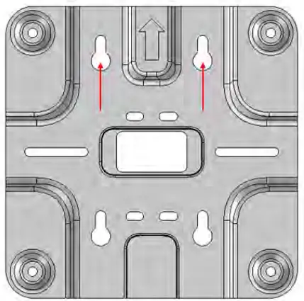
- Place the main bracket against the installation location on the wall. Use a pen or pencil to mark the points on the wall where the wall mounting holes are aligned.
After placing the bracket against the wall, mark these two locations on the wall with a pen or pencil.
- Use a power tool to drill holes in the marked locations, then insert the wall anchors into the holes.
- Use a power tool or a screwdriver to screw the wall mounting screws into the wall anchors. Leave about one-third of the screw length sticking out of the wall.
- Align the screw holes on the main bracket with the corresponding holes on the back of the Access point, then use four M4 screws to attach the main bracket to the Access Point.
Note: Make sure the arrow on the main bracket is aligned so that it is pointing toward the top side of the Access Point. - Align the wall mounting holes on the main bracket with the wall screws, then hook the Access Point onto the wall screws.
Proudct Specifications
| Outer Dimensions | 220 x 220 x 42 (mm) |
| CPU | Marvell CN9130-1600-NG-AUS-G |
| Memory | SDRAM: DDR4; 1 GB x 2 NAND Flash: 512 MB SPI NOR Flash’ 4 MB |
| Antennas | Dual-band Antenna x 4 2.4 GHz Antenna x 1 |
| PCB | Six-layer PCB; dimensions: 191.7 x 145.75 x 1.6 (mm) |
| mGiga PHY | Marvell 88E2110-A0-BWS4C000 x 2 |
| RF IC (2G/5G) | NXP 88W9064-A1-BWP2C000 x 2 |
| Ethernet port | 10/100/1000/2500 Mbps auto-negotiation Ethernet ports x 2 Supports PoE 802.3at |

 Access Point User Manual")


