SIMPSON Strong-Tie PA18 Wood Construction Connectors
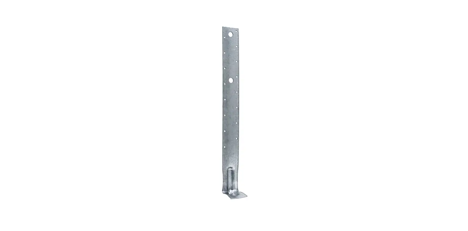
Strap-Tie Holdown
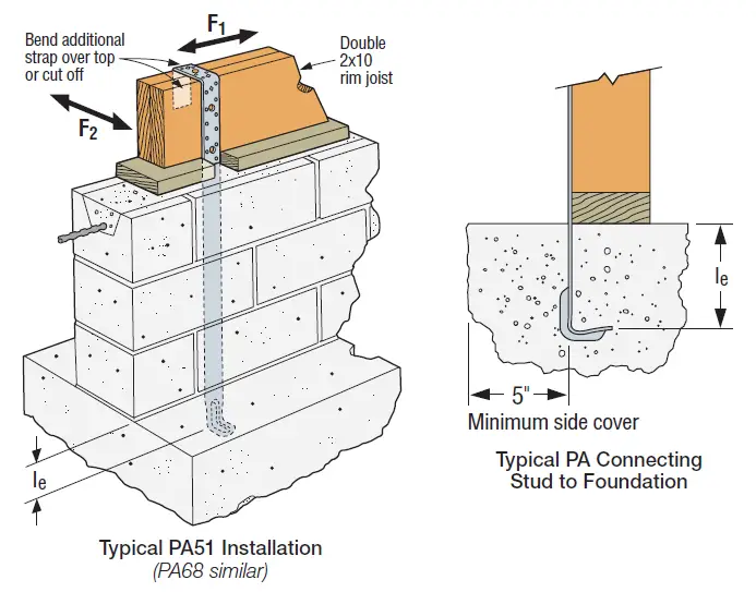
The PA strap-tie holdown is a wood-to-concrete connector that connects studs to the foundation to satisfy engineering and code requirements.
- Material: 12 gauge
- Finish: Galvanized or ZMAX® coating
Installation:
- Use all specified fasteners; see General Notes
- For additional length, an MST strap can be attached using 1⁄2″ bolts through existing holes
- Visit strongtie.com for additional information
Codes: See p. 11 for Code Reference Key Chart
These products are available with additional corrosion protection. For more information, see p. 14. Many of these products are approved for installation with Strong-Drive® SD Connector screws. See pp. 348–352 for more information.
| Wind and SDC A&B – Allowable Tension Loads | |||||||
| Model No. | Strap Length, L (in.) | le (in.) | Uncracked Concrete | Cracked Concrete | Code Ref. | ||
| Required Nails (in.) | Tension | Required Nails (in.) | Tension | ||||
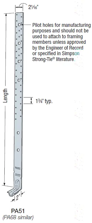
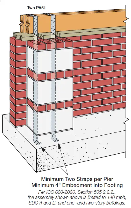
| PA51 | 51 | 4 | (10) 0.148 x 3 | 2,025 | (10) 0.148 x 3 | 2,025 | IBC, FL |
| PA68 | 70 | 4 | (10) 0.148 x 3 | 2,025 | (10) 0.148 x 3 | 2,025 | |
| SDC C–F – Allowable Tension Loads | |||||||
| Model No. | Strap Length, L (in.) | le (in.) | Uncracked Concrete | Cracked Concrete | Code Ref. | ||
| Required Nails (in.) | Tension | Required Nails (in.) | Tension | ||||
| PA51 | 51 | 4 | (10) 0.148 x 3 | 2,025 | (10) 0.148 x 3 | 1,840 | IBC, FL |
| PA68 | 70 | 4 | (10) 0.148 x 3 | 2,025 | (10) 0.148 x 3 | 1,840 | |
- Allowable loads have been increased for wind or earthquake loading with no further increase allowed. Reduce where other loads govern.
- Concrete shall have a minimum compressive strength of f’c = 2,500 psi.
- Masonry applications require grout-filled CMU with minimum compressive strength of f’m = 1,500 psi.
- Deflection at highest allowable load is as follows: PA51 and PA68 = 0.10″.
- PA allowable lateral loads are F1 = 795 lb. and F2 = 280 lb.
- #9 x 1 1/2″ Strong-Drive® SD Connector screws (SD9) may be substituted for table fasteners with no load reduction.
- Fasteners: Nail dimensions are listed diameter by length. See pp. 21–22 for fastener information
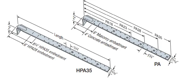
Purlin Anchors
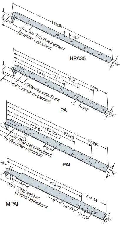
Purlin anchors offer solutions for wood-to-concrete and concrete-block connections which satisfy code requirements. The HPA offers the highest capacity in concrete. The PA’s dual-embedment line allows installation in concrete or concrete block.
- Material: PA/PAI — 12 gauge; HPA — 10 gauge; MPAI — 14 gauge
- Finish: Galvanized; PAs available HDG or ZMAX® coating
Installation:
- Use all specified fasteners; some models have extra fastener holes. See General Notes.
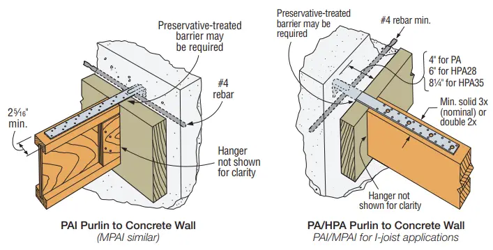
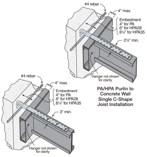
- Purlin anchor must hook around rebar.
- Allowable loads are for a horizontal installation into the side of a concrete or masonry wall.
- For vertical installation in the top of GFCMU, refer to engineering letter L-C-PAGFCMUUP on strongtie.com.
- Strap may be bent one full cycle. (Bent vertical 90° then bent horizontal.)
Edge Distance — Minimum concrete edge distance is 5″. Minimum concrete block left-to-right edge distance is 20″.
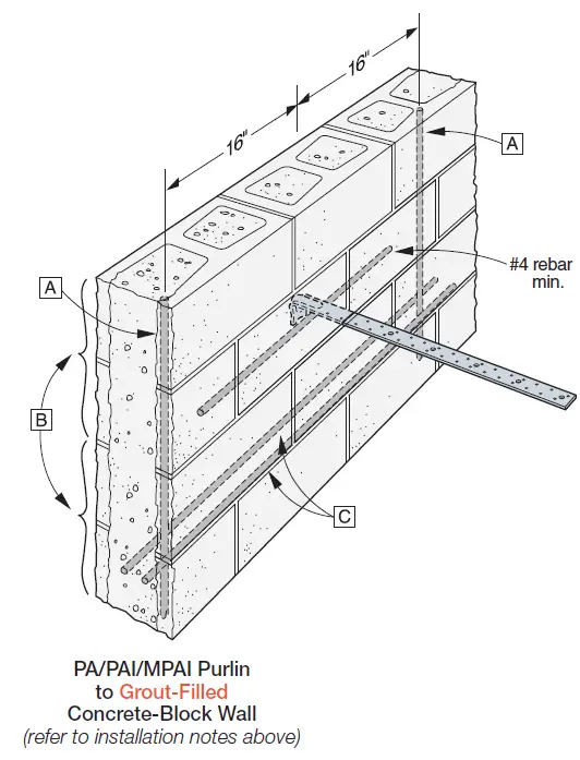
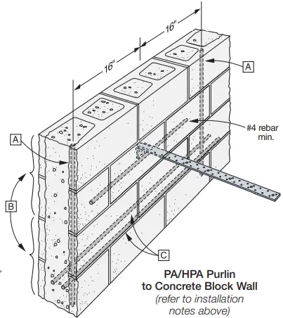
Concrete Block Wall — The minimum wall specifications are:
- A One #4 vertical rebar, 32″ long, 16” each side of anchor
- B Two courses of grout-filled block above and below the anchor (no cold joints allowed)
- C A horizontal bond beam with two #4 rebars, 40″ long, a maximum of two courses above or below the anchor
- D Minimum masonry compressive strength, f’m = 1,500 psi
Options: See LTT and HTT tension ties for alternate retrofit solutions
Codes: See p. 11 for Code Reference Key Chart
ASCE7 12.11.2.2.5 States:
… Diaphragm to structural wall anchorage using embedded straps shall have the straps attached to or hooked around the reinforcing steel, or otherwise terminated to effectively transfer forces to the reinforcing steel
These products are available with additional corrosion protection. For more information, see p. 14.
| Wind and SDC A&B – Allowable Tension Loads (160) | |||||||||||||
| Max Ledger Size | Model No. | Strap Length, L (in.) | Embed Length, le (in.) | Uncracked Concrete | Cracked Concrete | GFCMU Wall | Max. Allowable Strap Tension | Deflection at Allowable Load (in.) | Code Ref. | ||||
| Concrete | GFCMU | Required Nails (in.) | Tension | Required Nails (in.) | Tension | Required Nails (in.) | Tension | ||||||
|
4x Ledger | PA18 | 18 1/2 | 4 | 6 | (12) 0.148 x 3 | 2,430 | (12) 0.148 x 3 | 2,260 | (12) 0.148 x 3 | 1,890 | NA | 0.087 |
IBC, FL |
| PAI18 | 18 | 4 | 6 | (10) 0.148 x 11/2 | 2,025 | (10) 0.148 x 1 1/2 | 2,025 | (9) 0.148 x 1 1/2 | 1,055 | NA | 0.1 | ||
| PA23 | 233⁄4 | 4 | 6 | (16) 0.148 x 3 | 3,220 | (12) 0.148 x 3 | 2,260 | (16) 0.148 x 3 | 2,815 | NA | 0.118 | ||
| PAI23 | 23 | 4 | 6 | (15) 0.148 x 1 1/2 | 3,035 | (12) 0.148 x 1 1/2 | 2,260 | (14) 0.148 x 1 1/2 | 1,805 | NA | 0.158 | ||
| PA28 | 29 | 4 | 6 | (16) 0.148 x 3 | 3,230 | (12) 0.148 x 3 | 2,260 | (16) 0.148 x 3 | 2,815 | NA | 0.085 | ||
| PAI28 | 29 | 4 | 6 | (16) 0.148 x 11/2 | 3,230 | (12) 0.148 x 1 1/2 | 2,260 | (16) 0.148 x 1 1/2 | 2,705 | NA | 0.167 | ||
| PA35 | 35 | 4 | 6 | (16) 0.148 x 3 | 3,230 | (12) 0.148 x 3 | 2,260 | (16) 0.148 x 3 | 2,815 | NA | 0.085 | ||
| PAI35 | 35 | 4 | 6 | (16) 0.148 x 11/2 | 3,230 | (12) 0.148 x 1 1/2 | 2,260 | (18) 0.148 x 1 1/2 | 2,815 | NA | 0.13 | ||
| MPAI32 | 331/2 | 5 1/2 | (16) 0.148 x 1 1/2 | 2,885 | (16) 0.148 x 1 1/2 | 2,885 | (16) 0.148 x 1 1/2 | 2,355 | NA | 0.167 | |||
| MPAI44 | 451/2 | 5 1/2 | (16) 0.148 x 1 1/2 | 2,885 | (16) 0.148 x 1 1/2 | 2,885 | (24) 0.148 x 1 1/2 | 2,865 | NA | 0.167 | |||
| HPA28 | 321/2 | 6 | 6 | (22) 0.148 x 3 | 5,145 | (20) 0.148 x 3 | 4,675 | — | — | NA | 0.133 | ||
| HPA35 | 381/2 | 8 1/4 | 8 1/4 | (22) 0.148 x 3 | 5,145 | (22) 0.148 x 3 | 5,145 | — | — | NA | 0.132 | ||
| SDC C–F – Allowable Tension Loads (160) | |||||||||||||
| Max Ledger Size | Model No. | Strap Length, L (in.) | Embed Length, le (in.) | Uncracked Concrete | Cracked Concrete | GFCMU Wall | Max. Allowable Strap Tension | Deflection at Allowable Load (in.) | Code Ref. | ||||
| Concrete | GFCMU | Required Nails (in.) | Tension | Required Nails (in.) | Tension | Required Nails (in.) | Tension | ||||||
|
4x Ledger | PA18 | 18 1/2 | 4 | 6 | (12) 0.148 x 3 | 2,430 | (10) 0.148 x 3 | 1,980 | (12) 0.148 x 3 | 1,890 | 3,220 | 0.087 |
IBC, FL |
| PAI18 | 18 | 4 | 6 | (10) 0.148 x 1 1/2 | 2,025 | (10) 0.148 x 1 1/2 | 1,980 | (9) 0.148 x 1 1/2 | 1,055 | 4,180 | 0.1 | ||
| PA23 | 233⁄4 | 4 | 6 | (14) 0.148 x 3 | 2,830 | (10) 0.148 x 3 | 1,980 | (16) 0.148 x 3 | 2,815 | 3,220 | 0.118 | ||
| PAI23 | 23 | 4 | 6 | (14) 0.148 x 1 1/2 | 2,830 | (10) 0.148 x 1 1/2 | 1,980 | (14) 0.148 x 1 1/2 | 1,805 | 4,180 | 0.158 | ||
| PA28 | 29 | 4 | 6 | (14) 0.148 x 3 | 2,830 | (10) 0.148 x 3 | 1,980 | (16) 0.148 x 3 | 2,815 | 3,935 | 0.085 | ||
| PAI28 | 29 | 4 | 6 | (14) 0.148 x 1 1/2 | 2,830 | (10) 0.148 x 1 1/2 | 1,980 | (16) 0.148 x 1 1/2 | 2,705 | 5,070 | 0.167 | ||
| PA35 | 35 | 4 | 6 | (14) 0.148 x 3 | 2,830 | (10) 0.148 x 3 | 1,980 | (16) 0.148 x 3 | 2,815 | 3,935 | 0.085 | ||
| PAI35 | 35 | 4 | 6 | (14) 0.148 x 1 1/2 | 2,830 | (10) 0.148 x 1 1/2 | 1,980 | (18) 0.148 x 1 1/2 | 2,815 | 5,070 | 0.13 | ||
| MPAI32 | 331/2 | 5 1/2 | (16) 0.148 x 1 1/2 | 2,885 | (16) 0.148 x 1 1/2 | 2,885 | (16) 0.148 x 1 1/2 | 2,355 | 3,205 | 0.167 | |||
| MPAI44 | 451/2 | 5 1/2 | (16) 0.148 x 1 1/2 | 2,885 | (16) 0.148 x 1 1/2 | 2,885 | (24) 0.148 x 1 1/2 | 2,865 | 3,205 | 0.167 | |||
| HPA28 | 321/2 | 6 | 6 | (22) 0.148 x 3 | 5,145 | (18) 0.148 x 3 | 4,090 | — | — | 5,145 | 0.133 | ||
| HPA35 | 381/2 | 8 1/4 | 8 1/4 | (22) 0.148 x 3 | 5,145 | (22) 0.148 x 3 | 5,145 | — | — | 5,145 | 0.132 | ||
- Allowable loads have been increased for wind or earthquake loading with no further increase allowed. Reduce where other loads govern.
- Deflection listed is at the highest allowable load.
- Multiply Seismic and Wind ASD load values by 1.43 or 1.67, respectively, to obtain LRF D capacities.
- Nail quantities are based on Douglas fir (DF) or equivalent specific gravity of 0.50 or better. For use in spruce-pine-fir (SPF) or hem-fir (HF), nails quantities shall be increased by 1.15 to achieve loads listed.
- For wall anchorage systems in SDC C-F, the maximum strap allowable load shall not be less than 1.4 times the ASD anchor design load.
- Minimum center-to-center spacing is 3x the required embedment — i.e., standard installation is based on a minimum 5″ end distance.
- Structural composite lumber beams have sides that show either the wide face or the lumber strands/veneers. Values in the tables reflect installation into the wide face.
- Concrete shall have a minimum compressive strength of f’c = 3,000 psi.
- Grout-filled CMU (GFCMU) shall have a minimum compressive strength of f’m = 1,500 psi.
- PA models installed vertically in the top of a grouted masonry wall with 6″ embedment and (12) 0.148″ x 3″ nails achieve an allowable uplift load of 1,890 lb.
- For PA models, 0.148″ x 1 1/2″ nails may be substituted for 0.148″ x 3″ nails at 100% of listed load and with a 15% increase in deflection. For installation over sheathing, use 3″-long nails minimum.
- For PAI/MPAI models, 0.148″ x 1 1/2″ nails shall be used directly onto framing member. For installation over sheathing, use 2 1/8″-long nails minimum.
- Fasteners: Nail dimensions are listed diameter by length. See pp. 21–22 for fastener information.
PA/HPA
PA/HPA purlin anchors offer solutions for CFS to concrete and concrete block connections which satisfy code requirements. The HPA offers the highest capacity in concrete. The PAs dual embedment line allows installation in concrete or concrete block
- Material: PA — 12 gauge; HPA — 10 gauge
- Finish: Galvanized. PAs available in HDG or ZMAX® coating.
Installation
- Use all specified fasteners; some models have extra fastener holes. See General Notes.
- Purlin anchor must hook around rebar.
- Allowable loads are for a horizontal installation into the side of a concrete or masonry wall.
- Strap may be bent one full cycle. (Bent vertical 90° then bent horizontal.)
Edge Distance — Minimum concrete edge distance is 5″. Minimum concrete block left-to-right edge distance is 20″.
Concrete Block Wall — The minimum wall specifications are:
- A One #4 vertical rebar, 32″ long, 16″ each side of anchor.
- B Two courses of grout filled block above and below the anchor (no cold joints allowed).
- C A horizontal bond beam with two #4 rebars, 40″ long, a maximum of two courses above or below the anchor.
- D Minimum masonry compressive strength, f’m = 1,500 psi
Options: See S/LTT and HTT Tension Ties for alternate retrofit solutions
Codes: See p. 11 for Code Reference Key Chart
| Wind and SDC A&B — Allowable Load (lb.) | |||||||
| Fasteners8 | Non Cracked | Cracked | Max. Allowable Strap Tensile Capacity | Masonry Installation Tension Load | |||
| Rafter/Stud /Joist Thickness | |||||||
| 33 mil (20 ga.) | 43 mil (18 ga.) | 54 mil (16 ga.) | Tension Load | Tension Load | |||
| (16) #10 | (16) #10 | (8) #10 | 2,430 | 2,260 | NA | 1,895 | |
| (22) #10 | (16) #10 | (8) #10 | 3,220 | 2,260 | NA | 2,815 | |
| (22) #10 | (16) #10 | (8) #10 | 3,230 | 2,260 | NA | 2,815 | |
| (22) #10 | (16) #10 | (8) #10 | 3,230 | 2,260 | NA | 2,815 | |
| (28) #10 | (20) #10 | (10) #10 | 5,145 | 4,675 | NA | — | |
| (32) #10 | (22) #10 | (12) #10 | 5,145 | 5,145 | NA | — | |
| SDC C–F — Allowable Load (lb.) | |||||||
| (16) #10 | (16) #10 | (8) #10 | 2,340 | 1,980 | 3,220 | 1,895 | |
| (22) #10 | (16) #10 | (8) #10 | 2,830 | 1,980 | 3,220 | 2,815 | |
| (22) #10 | (16) #10 | (8) #10 | 2,830 | 1,980 | 3,935 | 2,815 | |
| (22) #10 | (16) #10 | (8) #10 | 2,830 | 1,980 | 3,935 | 2,815 | |
| (28) #10 | (20) #10 | (10) #10 | 5,145 | 4,090 | 5,145 | — | |
| (32) #10 | (22) #10 | (12) #10 | 5,145 | 5,145 | 5,145 | — | |
- Loads may not be increased for short-term loading.
- For concrete installs, the minimum compressive strength, f’c = 3,000 psi.
- Multiply Seismic and Wind ASD load values by 1.4 or 1.67, respectively, to obtain LRFD capacities.
- In accordance with 2012, 2015 and 2018 IBC Section 1613.1, detached one- and two-family dwellings in Seismic Design Category (SDC) C may use “Wind and SDC A&B” allowable loads.
- Minimum center-to-center spacing is 3 times the required embedment (Smin = 3 x le) for PA/HPAs acting in tension simultaneously, where le = embedment depth. Standard installation is based on minimum 5″ end distance.
- Install fasteners symmetrically and with a minimum of 4 of the required fasteners between the embedment line and the first tooling hole. In some cases, not all of the fastener holes will need to be filled.
- Per ASCE7-10, 12.11.2.2.2, for diaphragms in structures assigned to SDC C–F, maximum allowable strap tensile capacity shall be no less than 1.4 times the design load. Not applicable (NA) for Wind and SDC A&B designs.
- For PA straps, concrete embedment shown; embedment in masonry shall be 6″.
- See Fastening Systems catalog (C-F-2019) on strongtie.com for more information on Simpson Strong-Tie fasteners
These products are available with additional corrosion protection. Additional products on this page may also be available with this option. Check with Simpson Strong-Tie for details


