![]()
Driver Manual
FS-8700-43 Vesda
APPLICABILITY & EFFECTIVITY
Effective for all systems manufactured after March 2021.
![]()
Driver Revision: 1.03
Document Revision: 4.A
MSAsafety.com
MSA Safety
1991 Tarob Court
Milpitas, CA 95035
Website: www.MSAsafety.com
U.S. Support Information: +1 408 964-4443
+1 800 727-4377
Email: [email protected]
EMEA Support Information: +31 33 808 0590
Email: [email protected]
Description
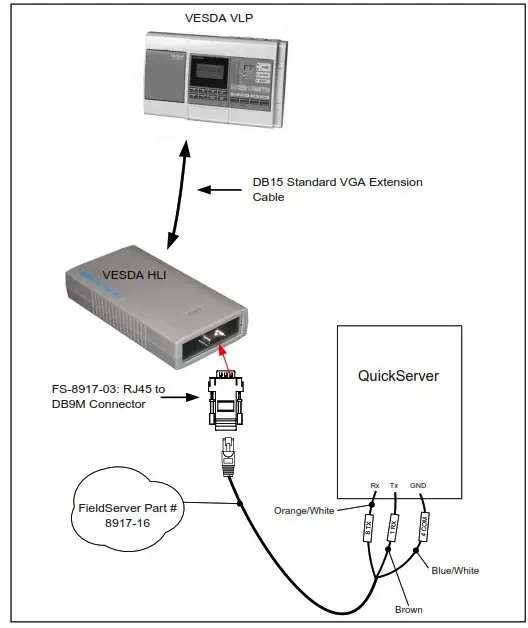
The VESDA driver allows the FieldServer to read data from VESDA LaserPLUS controllers (FAS or FD type) via the VESDA High-Level Interface (HLI) communications module, using RS-232. The FieldServer can be used only as a Client with this driver and operates in the HLI Master/Slave mode.
| FieldServer Mode | Nodes | Comments |
| Client | 1 | 1 HLI can be connected to each RS-232 port |
| Server | nil | Not applicable |
The information that follows describes how to expand upon the factory defaults provided in the configuration files included with the FieldServer.
Driver Scope of Supply
Supplied by MSA Safety
| Part # | Description |
| FS-8917-16 | RJ45 to terminal connector cable |
| FS-8917-03 | RJ45 to DB9M connector adapter |
Provided by the Supplier of 3 rd Party Equipment
2.2.1 Required 3 rd Party Hardware
| Part # | Description |
| VESDA VLP | |
| VESDA HLI | |
| DB15 Standard VGA Extension Cable |
Hardware Connections
The FieldServer RS-232 port is connected to the Vesda as shown in the connection drawing. Configure the Vesda according to the manufacturer’s instructions.
FS-8917-03 Pinouts
| FS Function | RJ45 Pin# | DB9M Pin# | Color |
| RX | 1 | 2 | White |
| CTS | 2 | 8 | Brown |
| DSR | 3 | 6 | Yellow |
| GND | 4 | 5 | Green |
| DTR | 6 | 4 | Black |
| RTS | 7 | 7 | Orange |
| TX | 8 | 3 | Blue |
Data Array Parameters
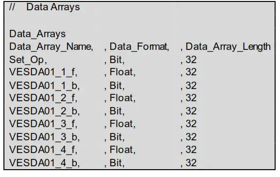
Data Arrays are “protocol neutral” data buffers for the storage of data to be passed between protocols. It is necessary to declare the data format of each of the Data Arrays to facilitate correct storage of the relevant data.
| Section Title | ||
| Data_Arrays | ||
| Column Title | Function | Legal Values |
| Data_Array_Name | Provide name for Data Array. | Up to 15 alphanumeric characters |
| Data_Format | Provide data format. Each Data Array can only takon one format. | Float, Bit, Byte, Uint16, Uint32, Sint16, Sint32 |
| Data_Array_Length | Number of Data Objects. Must be larger than the data storage area required by the Map Descriptors for the data being placed in this array. | 1-10000 |
Example
Client-Side Configuration
For detailed information on FieldServer configuration, refer to the FieldServer Configuration Manual. The information that follows describes how to expand upon the factory defaults provided in the configuration files included with the FieldServer (see “.csv” sample files provided with the FieldServer).
This section documents and describes the parameters necessary for configuring the FieldServer to communicate with a Vesda Server.
The configuration file tells the FieldServer about its interfaces, and the routing of data required. In order to enable the FieldServer for Vesda communications, the driver independent FieldServer buffers need to be declared in the “Data Arrays” section, the destination device addresses need to be declared in the “Client-Side Nodes” section, and the data required from the servers need to be mapped in the “Client-Side Map Descriptors” section. Details on how to do this can be found below.
NOTE: In the following tables, * indicates an optional parameter and bold legal values are default.
Client-Side Connection Parameters
| Section Title | ||
| Connections | ||
| Column Title | Function | Legal Values |
| Port | Specify which port the device is connected to the FieldServer. | P1-P2, R1-R21 |
| Baud* | Specify baud rate.2 | 110 – 115200, standard baud rates only; 9600 |
| Parity* | Specify parity. | None |
| Data_Bits* | Specify data bits. | 8 |
| Stop_Bits* | Specify stop bits. | 1 |
| Timeout* | Specify time allowed between poll and responses. | ≤10s, 2s |
| IC_timeout* | This parameter monitors the time between characters in response. If the time exceeds the IC_Timeout the response is discarded and considered a timeout. | 0-1.0s, 0.5s |
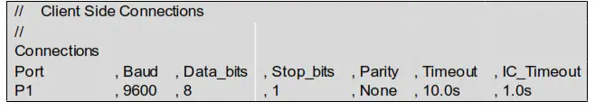
Example
- Not all ports shown are necessarily supported by the hardware. Consult the appropriate Instruction manual for details of the ports available on specific hardware.
- Most Vesda Panels are configured for Baud 19200.
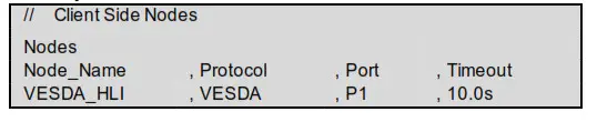
Client-Side Node Descriptors
| Section Title | ||
| Nodes | ||
| Column Title | Function | Legal Values |
| Node_Name | Provide a name for the node. | Up to 32 alphanumeric characters |
| Protocol | Specify the protocol used. | VESDA |
| Port | Specify which port the device is connected to the FieldServer. | P1-P2, R1-R23 |
| Timeout* | Specify time allowed between poll and responses. | ≤10s, 2s |
Example
Client-Side Map Descriptor Parameters
5.3.1 Field Server Specific Map Descriptor Parameters
| Column Title | Function | Legal Values |
| Map_Descriptor Name | Name of this Map Descriptor. | Up to 32 alphanumeric characters |
| Data Array_Name | Name of Data Array where data is to be stored in the FieldServer. Only used for commands 1,4,6,12. | One of the Data Array names from Section 4; Must be of type BIT |
| Data Array_Offset | Starting location in Data Array. | 0 to (Data Array_Length-1) as specified in Section 4 |
| Function | Function of Client Map Descriptor. A Command is a writer, and a Response is a read | Rd bc, Wrbc, Wrbx, Awt |
3. Not all ports shown are necessarily supported by the hardware. Consult the appropriate Instruction manual for details of the ports available on specific hardware.
5.3.2 Driver Related Map Descriptor Parameters
| Column Title | Function | Legal Values |
| Node Name_ | Name of Node to fetch data from. | One of the node names specified in “Client Node Descriptor above |
| Data_Type | Data type. | Dig_input, Dig_output, – |
| Length | Length of Map Descriptor. | 1 to end of the data block. |
| Address | Starting address of reading block. | The start bit number of the data of interest |
| Command | The command id as given in the notes. | 1,4, 6, 10,12, 16, 27, 29 |
| Network* | The network number. | 0-255, 0 |
| Zone* | The zone number. | 0-255, 0 |
| Sector* | The sector number. | 1-255 or 0 to read the average smoke level and highest alarm. |
| DA— Bit— Name* | Name of Data Array where data is to be stored in the FieldServer. Used for commands 10 and 16. | One of the Data Array names specified in Section 4; Must be of type BIT, – |
| DA Bit Offset* — — | Starting location in Data Array. Used for commands 10 and 16. | 0 to (Data_Array_Length -1)as specified in Section 4, – |
| DA Float Name* — — | Name of Data Array where data is to be stored in the FieldServer. Only used for command 10. | One of the Data Array names is specified in Section 4. Must be of type FLOAT, – |
| DA Float Offser — — | Starting location in Data Array. Only used for command 10. | 0 to (Data_Array_Length -1) as specified in Section 4, – |
| DA_Byte_N am e* | Name of Data Array where data is to be stored in the FieldServer. Only used for command 16. | One of the Data Array names specified in Section 4; Must be of type BYTE, – |
| DA_Byte_offser | Starting location in Data Array. Only used for command 16. | 0 to (Data_Array_Length -1)as specified in Section 4, – |
| DA Parameters | Name of Data Array where data is to be stored in the FieldServer. Only used for command 29. | One of the Data Array names specified in Section 4; – |
| DA_Parameters Offset | Starting location in Data Array. Only used for command 29. | 0 to (Data_Array_Length -1)as specified in Section 4, – |
Map Descriptor Example
Useful Features
Vesda Mapping Format for Command 1 (Set Operation)
This command is mandatory as it turns the VESDA system into a master-slave relationship and is of type BIT. The content of the data is irrelevant. The format for the data is as follows:
6.1.1 Data Arrays
| Column Title | Function | Legal Values |
| Data_Array_Name | Provide name for Data Array | Up to 15 alphanumeric characters |
| Data_Format | Provides data format | BIT |
| Data_Array_Length | Number of Data Objects | 8 |
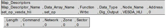
6.1.2 Client Side Map Descriptors
| Column Title | Function | Legal Values |
| Map_Descriptor Narne | Name of this Map Descriptor. | Up to 32 alphanumeric characters |
| Data_Array_Name | Name of Data Array where data is to be stored in the FieldServer. | Data_Array_Name defined in 6.1.1 |
| Function | The function of Client Map Descriptor. | Wrbc, Wrbx |
| Node Name _ | Name of Node to fetch data from. | One of the Node names specified in Section 5.2 |
| Data_Type | Data type. | Dig_Output |
| Length | Length of Map Descriptor. | 1-16 (must not overflow the data array) |
| Address* | Starting address of read block. | 0-15, 0 |
| Command | The command ID. | 1 |
| Network* | The network number. | 1-255, 0 |
| Zone* | The zone number. | 1-255, 0 |
| Sector* | The sector number. | 1-255, 0 |
Example
Vesda Mapping Format for Command 4 (Zone Update)
This request returns the Current Zone Status in a BIT data array. The format for the data is as follows:
6.2.1 Data Arrays
| Column Title | Function | Legal Values |
| Data_Array_Name | Provide a name for Data Array | Up to 15 alphanumeric characters |
| Data_Format | Provides data format. | BIT |
| Data_Array_Length | A number of Data Objects. | 1 – 16 |
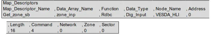
6.2.2 Client Side Map Descriptors
| Column Title | Function | Legal Values |
| Map_Descriptor Narne | Name of this Map Descriptor. | Up to 32 alphanumeric characters |
| Data_Array_Name | Name of Data Array where data is to be stored in the FieldServer. | Data_Array_Name defined in Section 6.2.1 |
| Data_Array_Location | Starting location in Data Array. | 0 -15 |
| Function | Function of Client Map Descriptor. | Rdbc |
| Node Name _ | Name of Node to fetch data from. | One of the Node names specified in Section 5.2 |
| Data_Type | Data type. | Dig_input |
| Length | Length of Map Descriptor. | 1-16 (must not overflow the data array) |
| Address | Starting address of read block. | 0-15 |
| Command | The command ID. | 4 |
| Network* | The network number. | 1-255, 0 |
| Zone* | The zone number. | 1-255, 0 |
| Sector* | The sector number. | 1-255, 0 |
6.2.3 Data Block Description
NOTE: The Bit value 1 indicates TRUE; 0 indicates FALSE.
| Bit Offset | Function Other | Bit Offset | Function |
| 0 | Other Zone Info | 8 | Fault Power |
| 1 | Scanning | 9 | Fault Urgent |
| 2 | Autolearning | 10 | Fault Zone |
| 3 | Normalizing | 11 | Fault System |
| 4 | Isolated | 12 | Alarm Fire2 |
| 5 | Fault Filter | 13 | Alarm Fire1 |
| 6 | Fault Airflow | 14 | Alarm Action |
| 7 | Fault Network | 15 | Alarm Alert |
Example
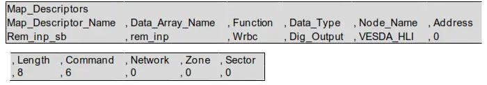
Vesda Mapping Format for Command 6 (Remote Input)
This command sends the Remote Input in a BIT data array.
6.3.1 Data Array
| Column Title | Function | Legal Values |
| Data_Array_Name | Provide a name for Data Array. | Up to 32 alphanumeric characters |
| Data_Format | Provides data format. | BIT |
| Data_Array_Lengt | Number of Data Objects. | 8-Jan |
6.3.2 Client Map Descriptors
| Column Title | Function | Legal Values |
| Map_Descriptor Name | Name of this Map Descriptor. | Up to 32 alphanumeric characters |
| Data_Array_Name | Name of Data Array where data is to be stored in the FieldServer. | Data_Array_Name defined in Section 6.3.1 |
| Data_Array_Location | Starting location in Data Array. | 0-7 |
| Function | Function of Client Map Descriptor. | Wrbx |
| Node Name _ | Name of Node to fetch data from. | One of the Node names specified in Section 5.2 |
| Data_Type | Data type. | Digoutput |
| Length | Length of Map Descriptor. | 1-8 (must not overflow the data rf array) |
| Address | Starting address of read block. | 0-7 |
| Command | The command ID. | 6 |
| Network* | The network number. | 1-255, 0 |
| Zone* | The zone number. | 1-255, 0 |
| Sector | The sector number. | 1-255, 0 |
6.3.3 Data Block Description
NOTE: The Bit value 1 indicates TRUE; 0 indicates FALSE.
NOTE: Only 1 of the 8 bits may be set in one command.
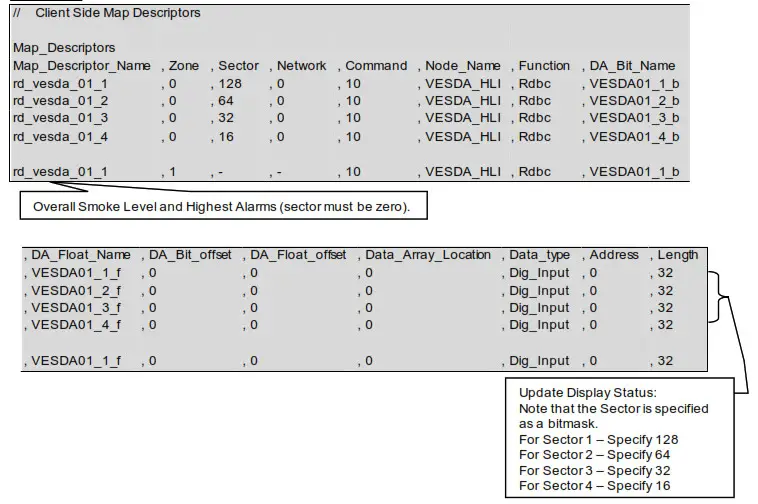
Vesda Mapping Format for Command 10 (Update Display Status)
This request returns the Current Display Status in a split data array (2 data arrays of different types in one map descriptor). The format for the data is as follows:
6.4.1 Data Arrays 1
| Column Title | Function | Legal Values |
| Data_Array_Name | Provide a name for Data Array. | Up to 15 alphanumeric characters |
| Data_Format | Provides data format. | BIT |
| Data_Array_Length | A number of Data Objects. | 32 |
6.4.2 Data Arrays 2
| Column Title | Function | Legal Values |
| Data_Array_Name | Provide a name for Data Array. | Up to 15 alphanumeric characters |
| Data_Format | Provides data format. | FLOAT |
| Data_Array_Length | A number of Data Objects. | 32 (only first position used) |
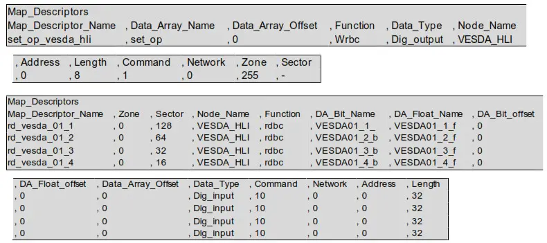
6.4.3 Client Side Map Descriptors
| Column Title | Function | Legal Values |
| Map_Descriptor Narne | Name of this Map Descriptor. | Up to 32 alphanumeric characters |
| Data_Array_Location | Starting location in Data Array. | 0-31 |
| Function | The function of Client Map Descriptor. | Rd bc |
| Node Name _ | Name of Node to fetch data from. | One of the Node names specified in Section 5.2 |
| Data_Type | Data type. | Dig_input |
| Length | Length of Map Descriptor. | 32 |
| Address | Starting address of reading block. | 0-31 |
| Command | The command ID. | 10 |
| Network* | The network number. | 1-255, 0 |
| Zone* | The zone number. | 1-255, 0 |
| Sector | The sector number. | 1-255, 0 |
| DA_Bit_Name | Name of Data Array where data is to be stored in the FieldServer. | Data Array 1 name defined in Section 6.4.1 |
| DA_Bit_Offset | Starting location in Data Array. | 0 to (Data_Array_Length 1)as Section specified in 6.4.1 |
| DA Float Name | Name of Data Array where data is to be stored in the FieldServer. | Data Array 2 name defined in Section 6.4.2 |
| DA_Float Offset | Starting location in Data Array. | 0 to (Data_Array_Length 1)as Section specified in 6.4.1 |
6.4.4 Data Block 1 Description
NOTE: The Bit value 1 indicates TRUE; 0 indicates FALSE.
| Bit Offset | Function |
| 0 | Reserved Flash |
| 1 | Fault Filter Flash |
| 2 | Fault Airflow Flash |
| 3 | Fault Network Flash |
| 4 | Fault Power Flash |
| 5 | Fault Urgent Flash |
| 6 | Fault Zone Flash |
| 7 | Fault System Flash |
| 8 | OK Flash |
| 9 | Isolate Flash |
| 10 | Fault Minor Flash |
| 11 | Fault Major Flash |
| 12 | Alarm Fire2 Flash |
| 13 | Alarm Fire1 Flash |
| 14 | Alarm Action Flash |
| 15 | Alarm Alert Flash |
| 16 | Reserved |
| 17 | Fault Filter |
| 18 | Fault Airflow |
| 19 | Fault Network |
| 20 | Fault Power |
| 21 | Fault Urgent |
| 22 | Fault Zone |
| 23 | Fault System |
| 24 | OK |
| 25 | Isolate |
| 26 | Fault Minor |
| 27 | Fault Major |
| 28 | Alarm Fire2 |
| 29 | Alarm Fire1 |
| 30 | Alarm Action |
| 31 | Alarm Alert |
6.4.5 Data Block 2 Description
| Float Offset | Function |
| 0 | Average Smoke Level (Sector must be set to zero) |
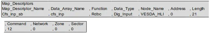
Vesda Mapping Format for Command 12 (Current Fault Status)
This command sends the Current Fault Status in a BYTE data array. The format for the data is as follows:
6.5.1 Data Arrays
| Column Title | Function | Legal Values |
| Data_Array_Name Data_Format | Provide a name for Data Array | Up to 15 alphanumeric characters |
| Data_Array_Length | Provides data format. | BYTE |
| Column Title | Number of Data Objects. | 1 – 21 |
6.5.2 Client Side Map Descriptors
| Column Title | Function | Legal Values |
| Map_Descriptor Narne | Name of this Map Descriptor. | Up to 32 alphanumeric characters |
| Data_Array_Name | Name of Data Array where data is to be stored in the FiekiServer. | Data_Array_Name defined in Section 6.5.1 |
| Data_Array_Location | Starting location in Data Array. | 0-20 |
| Function | Function of Client Map Descriptor. | Rdbc |
| Node Name _ | Name of Node to fetch data from. | One of the Node names specified in Section 5.2 |
| Data_Type | Data type. | Dig_input |
| Length | Length of Map Descriptor. | 1-21 (must not overflow the data array) |
| Address | The starting address of the read block. | 0-20 |
| Command | The command ID. | 12 |
| Network* | The network number. | 1-255, 0 |
| Zone* | The zone number. | 1-255, 0 |
| Sector* | The sector number. | 1-255, 0 |
6.5.3 Data Block Description
NOTE: The Byte value 1 indicates TRUE; 0 indicates FALSE.
| Byte Offset | Function |
| 0 | Number of faults |
| 1 – 20 | Fault list |
Example
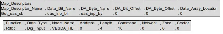
Vesda Mapping Format for Command 16 (Update Airflow Status)
This request returns the Current Airflow Status in a split data array (2 data arrays of different types in one
map descriptor). The format for the data is as follows:
6.6.1 Data Arrays 1
| Column Title | Function | Legal Values |
| Data_Array_Name Data_Format | Provide a name for Data Array. | Up to 15 alphanumeric characters |
| Data_Array_Length | Provides data format. | BIT |
| Column Title | Number of Data Objects. | 4 |
6.6.2 Data Arrays 2
| Column Title | Function | Legal Values |
| Data_Array_NameData_Format | Provide a name for Data Array. | Up to 15 alphanumeric characters |
| Data_Array_Length | Provides data format. | BYTE |
| Column Title | Number of Data Objects. | 4 |
6.6.3 Client Side Map Descriptors
| Node Name | Name of Node to fetch data from. | One of the Node names specified in Section 5.2 |
| Data_Type | Data type. | Dig_input |
| Length | Length of Map Descriptor. | 4 |
| Address | Starting address of reading block. | 0-3 |
| Command | The command ID. | 16 |
| Network* | The network number. | 1-255, 0 |
| Zone* | The zone number. | 1-255, 0 |
| Sector | The sector number. | 1-255, 0 |
| DA_Bit_Name | Name of Data Array where data is to be stored in the FieldServer. | Data Array 1 name defined in Section 6.6.1 |
| DA_Bit_offset | Starting location in Data Array. | 0 to (Data_Array_Length 1) as specified in Section 6.6.1 |
| DA_Byte_Name | Name of Data Array where data is to be stored in the FieldServer. | Data Array 2 name defined in Section 6.6.2 |
| DA_Byte_offset | Starting location in Data Array. | 0 to (Data_Array_Length 1) as specified in Section 6.6.1 |
6.6.4 Data Block 1 Description
NOTE: The BIT value 1 indicates OPEN; 0 indicates CLOSE.
| BIT Offset | Function |
| 0 | Pipe1 status |
| 1 | Pipe2 status |
| 2 | Pipe3 status |
| 3 | Pipe4 status |
6.6.5 Data Block 2 Description
| BYTE Offset | Function |
| 0 | Airflow in pipe 1 as a percentage of normalized pipe airflow |
| 1 | Airflow in pipe 2 as a percentage of normalized pipe airflow |
| 2 | Airflow in pipe 3 as a percentage of normalized pipe airflow |
| 3 | Airflow in pipe 4 as a percentage of normalized pipe airflow |
Example
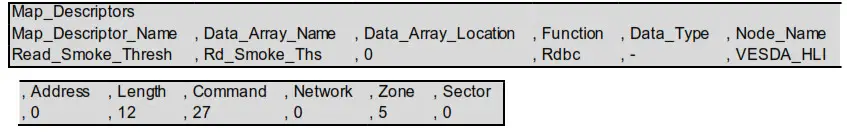
Vesda Mapping Format for Command 27 (Get Overall Smoke Thresholds)
This request returns the Overall Smoke Thresholds in a FLOAT data array. The format for the data is as follows:
6.7.1 Data Arrays
| Column Title | Function | Legal Values |
| Data_Array_Name Data_Format | Provide name for Data Array. | Up to 15 alphanumeric characters |
| Data_Array_Length | Provides data format. | Float |
| Column Title | Number of Data Objects. | 12 |
6.7.2 Client Side Map Descriptors
| Column Title | Function | Legal Values |
| Map_Descriptor Narne | Name of this Map Descriptor. | Up to 32 alphanumeric characters |
| Data_Array_Name | Name of Data Array where data is to be stored in the FieldServer. | Data_Array_Name defined in Section 6.7.1 |
| Data_Array_Location | Starting location in Data Array. | 0 |
| Function | Function of Client Map Descriptor. | Rdbc |
| Node Name _ | Name of Node to fetch data from. | One of the Node names specified in Section 5.2 |
| Data_Type | Data type. | |
| Length | Length of Map Descriptor. | 12 |
| Address | Starting address of reading block. | 0 |
| Command | The command ID. | 27 |
| Network* | The network number. | 1-255, 0 |
| Zone* | The zone number. | 1-255, 0 |
| Sector* | The sector number. | 1-255, 0 |
Example
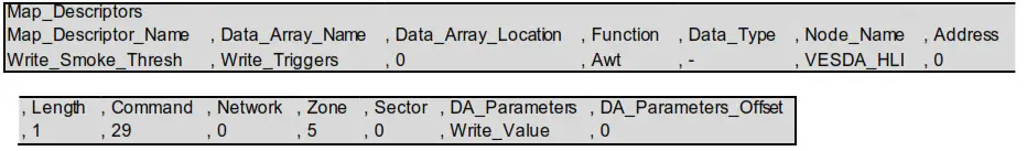
Vesda Mapping Format for Command 29 (Set Smoke Thresholds)
This command sets the Smoke Thresholds. The format for the data is as follows:
6.8.1 Data Arrays
| Column Title | Function | Legal Values |
| Data_Array_Name Data_Format | Provide a name for Data Array. | Up to 15 alphanumeric characters |
| Data_Array_Length | Provides data format. | Bit |
| Column Title | Number of Data Objects. | 1 |
6.8.2 Client Side Map Descriptors
| Column Title | Function | Legal Values |
| Map_Descriptor Name | Name of this Map Descriptor. | Up to 32 alphanumeric characters |
| Data_Array_Name | Name of Data Array where data is to be stored in the FieldServer. | Data_Array_Name defined in Section 6.8.1 |
| Data_Array_Location | Starting location in Data Array. | 0 |
| Function | Function of Client Map Descriptor. | AWT |
| Node Name _ | Name of Node to fetch data from. | One of the Node names specified in Section 5.2 |
| Data_Type | Data type. | – |
| Length | Length of Map Descriptor. | 1 |
| Address | Starting address of read block. | 0 |
| Command | The command ID. | 29 |
| Network* | The network number. | 1-255, 0 |
| Zone* | The zone number. | 1-255, 0 |
| Sector* | The sector number. | 1-255, 0 |
| DA_Parameters* | Name of Data Array where data is to be stored in the FieldServer. | Data Array Name defined in Section 6.8.1 |
| DA_Parameters Offset* | Starting location in Data Array. | 0 |
6.8.3 Data Block Description
NOTE: 1 indicates TRUE; 0 indicates FALSE.
| Bit Offset | Function |
| 0 | Alert Smoke Threshold Day |
| 1 | Action Smoke Threshold Day |
| 2 | Fire-1 Smoke Threshold Day |
| 3 | Fire-2 Smoke Threshold Day |
| 4 | Alert Smoke Threshold Night |
| 5 | Action Smoke Threshold Night |
| 6 | Fire-1 Smoke Threshold Night |
| 7 | Fire-2 Smoke Threshold Night |
| 8 | Sector Scanner for LaserScanner Sector 1 |
| 9 | Sector Scanner for LaserScanner Sector 2 |
| 10 | Sector Scanner for LaserScanner Sector 3 |
| 11 | Sector Scanner for LaserScanner Sector 4 |
Example
Troubleshooting
Vesda Panel Start-up Delay
When the HLI is powered on the FieldServer will not be able to communicate with the Panel for 10 to 30 seconds. During this time the HLI starts up its application code and initializes various internal parameters.
Reading Smoke Levels on the Vesda Panels
The Vesda panel only allows the driver to read the average Smoke Level on all the ports. Polling for individual sector smoke levels will always return a value of zero.
- Zone setup – If the zone on the Panel has not been configured the zone must be set to zero in the FieldServer configuration file.
- Sector setup – Setting the sector to zero will allow the driver to poll for the average smoke level.
Refer to Section 6.4 for more information.
Vesda Driver Manual


