METAL WORK EB 80 Control Module User Manual
INTRODUCTION
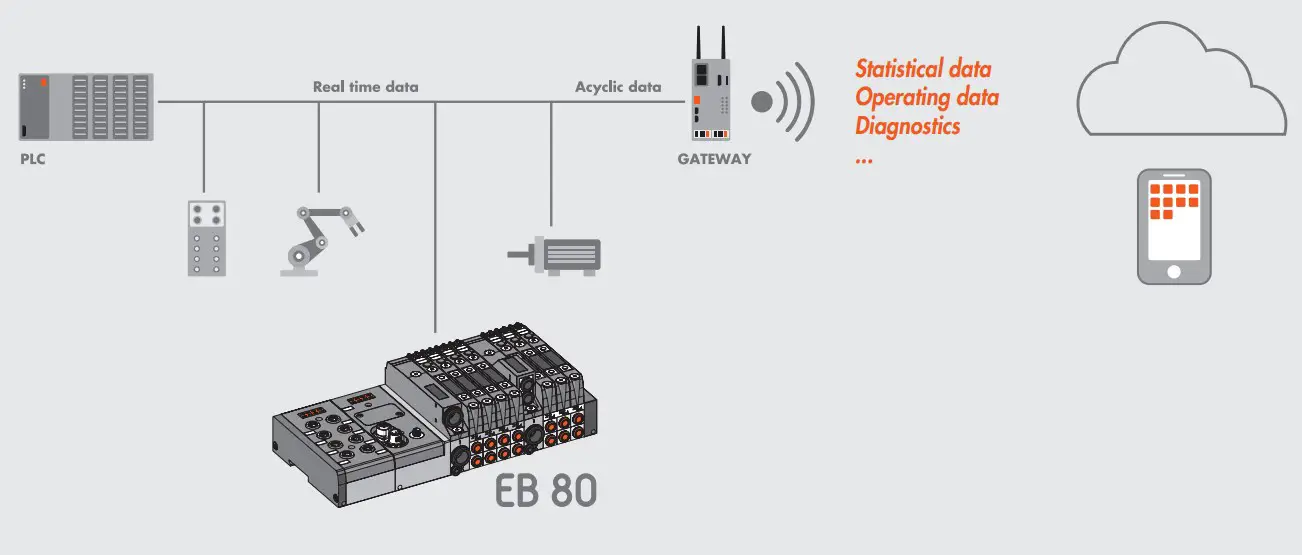
Electrical connection modules can be used to complement the EB 80 with the main field buses available in the market. In this way, the control system (generally a PLC) can handle in real time the behaviour of the solenoid valve island, including signal modules.
With the introduction of the I4.0 version, the field bus connection modules also send to the network the historical and diagnostic data relating to the behaviour of the island (such as the number of cycles for each solenoid pilot, total activation time and alarms) and the controlled pneumatic circuit (such as the delay times in sensor switching and actuator activation times).
This data is also sent to the control system and can be handled differently depending on the situation: in some cases, it can be used in real time, like in the case of fault alarms; in other cases, it can be sent to a storage local unit or one remotely controlled on a cloud server, and is analysed in a subsequent stage; in other cases, the alarms can be sent to a teleservice station that can monitor the state of the system remotely
The new advanced EB 80 diagnostic functions, known as EB 80 I4.0, provide a powerful analysis tool for traditional maintenance operations, ensuring the safe, reliable and lasting operation of production units.
They are available for all electrical connections with fieldbuses and bases marked I4.0, with advanced diagnostics integrated in accordance with Industry 4.0 philosophy.
These functions use the original EB 80 diagnostics, integrating them with the ability of the station itself to control IOs.
They re-organise and optimise maintenance management by developing predictive maintenance in order to:
- predict faults;
- intervene early to avoid system downtime;
- have all information on equipment operation available in real time;
- monitor component end-of-lifetime;
- optimise warehouse spare parts management.
This makes it possible to turn the data collected into concrete actions using standard EB 80 stations without needing additional modules
Description of EB 80 I4.0 functions
- System data:
- EB 80 system startup counter;
- supply alert counter.
- Valve data. Each valve base for each solenoid valve permanently stores the following information:
- cycle counter;
- counter for total solenoid valve excitation time, operating hour meter of the pressure regulator;
- activation of an indication of exceeding 60% of the average life;
- short circuit alert counter;
- open circuit alert counter.
- Electropneumatic system control functions (data updated with each cycle):
- measurement of the delay between activating the solenoid valve “A” and actuator movement commencing via the signal of sensor “B”, with delays that exceed the limit flagged;
- measurement of actuator movement time using two linked sensors “B” and “C”, with exceeded time limits flagged;
- measurement of the delay between deactivating the solenoid valve “A” (or activating a second valve) and actuator return commencing via the signal of sensor “B”, with exceeded time limits flagged;
- measurement of actuator return time using two linked sensors “B” and “C”, with exceeded time limits flagged;
- counter for actuator range of motion.

![]() WARNING
WARNING
EB 80 I4.0 functions are available for software versions installed after:
EtherNet/IP 2.0 / Valve bases 7.03 with I4.0 logo / EDS METALWORK EB80 – EIS V2.00
SYSTEM CONFIGURATION
Configure the EB 80 system with all the modules installed in the system in use, as described in the EB 80 EtherNet/IP user manual.
Then complete the configuration of I4.0 functions.
Configuring the EB 80 I4.0 functions
- I4.0 Enable: enable of diagnostic functions
0 = Functions disabled
1 = Functions enabled - Valve data update time: the system and valve data stored in the electronic circuit boards of the valve bases are updated with the time set for this parameter. It is advisable to set a time greater than 1000 ms to avoid overloading the system.
- Actuator data update time: the time relating to the actuation and reset of the controlled actuators. A short time, e.g. 50ms, must be set to obtain data in real time.
DESCRIPTION OF FUNCTIONS
System data
Actuation counter: ìshowing the number of system actuations; it is updated every time it is switched on.
Power alarm counter: showing it indicates the number of alarms caused by power supply values outside the 10.8-31.2 VDC permitted range.
Valve data
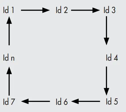
The system reads the data relating to each solenoid pilot cyclically and sequentially at the time set under “Valve data update time”.
The valve number associated with the data is shown with the valve ID byte. In order to avoid overloading the system, it is advisable to set a long time, e.g. in a system with 8 valves and a set update time of 1000 ms, the data of each valve is updated every 8 seconds.
Pressure Regulator Data
The ID of the Pressure Regulators is subsequent to the ID of the last valve installed in the system.
Cycle counter: showing the number of actuations of each solenoid pilot. When the number of cycles exceeds 60% average life, set at 30,000,000 cycles for the valves and 60,000,000 for pressure regulators, an alert comes on to indicate that the average operating lifetime has been exceeded.
Total solenoid valve energising time counter / operating hour meter of the pressure regulator: it indicates the total actuation time of the solenoid pilots / indicates the total working hours of the Pressure Regulators.
Short circuit alarm counter: it indicates the number of alarms due to the short circuiting of each solenoid valve.
Open-circuit alarm counter: it indicates the number of alarms due to the interruption of the solenoid valve reel of each solenoid pilot.
IMPORTANT: a command relating to free positions, e.g. dummy valves, bypass valves or the second pilot of one-pilot valves, generates an open-circuit alarm.
Actuation function
This function enables the control of the electro-pneumatic system. Its operation requires the installation of an input digital signal module in the system. Up to 10 actuator modules can be installed.
Actuator parameters
Pilot 1 Id: enter the pilot number corresponding to the valve associated with the actuator to be controlled.
Pilot 2 Id: enter the second pilot number corresponding to the valve associated with the actuator to be controlled, when a two-pilot valve is used. Enter 0 when using one-pilot valves.
Example of pilot Id assignment
Base for 8-control valves. Valves with one or two solenoid pilots can be mounted
| Type of valve | 2 solenoid pilots valve | 1 solenoid pilots valve | Dummy valve or Bypass | 1 solenoid pilots valve |
| Solenoid pilot 1 | 14 | 14 | – | 14 |
| Solenoid pilot 2 | 12 | – | – | – |
| Output | Out 1 | Out 3 | Out 5 | Out 7 |
| Out 2 | Out 4 | Out 6 | Out 8 | |
| Pilot 1 Id | 1 | 3 | – | 7 |
| Pilot 2 Id | 2 | – | – | 8 |
Limit switch 1 Input ID: enter the input number of the digital input module to which the first sensor of the actuator limit switch is connected.
Limit switch 2 Input ID: enter the input number of the digital input module to which the first sensor of the actuator limit switch is connected.
Actuation delay: the time elapsing between the enabling of electrical pilot 1 and the actuator movement, which is read by verifying that the limit switch 1 input has been disabled.
Actuation delay % tolerance: set the percentage tolerance allowed for the enabling time. Any plus or minus deviation from the set tolerance causes a signalling bit to come on
| 00 = 0% | 04 = 20% | 08 = 40% | 12 = 60% |
| 01 = 5% | 05 = 25% | 09 = 45% | 13 = 65% |
| 02 = 10% | 06 = 30% | 10 = 50% | 14 = 70% |
| 03 = 15% | 07 = 35% | 11 = 55% | 15 = 75% |
Reset delay: the time elapsing between the disabling of electrical pilot 1 or the enabling of electrical pilot 2 in the case of a two-pilot valve and the actuator movement, which is read by verifying that the limit switch 2 input has been disabled.
Reset delay % tolerance: set the percentage tolerance allowed for the reset time. Any plus or minus deviation from the set tolerance causes a signalling bit to come on.
| 00 = 0% | 04 = 20% | 08 = 40% | 12 = 60% |
| 01 = 5% | 05 = 25% | 09 = 45% | 13 = 65% |
| 02 = 10% | 06 = 30% | 10 = 50% | 14 = 70% |
| 03 = 15% | 07 = 35% | 11 = 55% | 15 = 75% |
Actuation time: the time it takes the actuator to move via the two associated sensors.
Actuation time % tolerance: enter the percentage tolerance allowed for the actuation time. Any plus or minus deviation from the set tolerance causes a signalling bit to come on (see tables “Actuation delay % tolerance” and “Reset delay % tolerance”).
Return time: the time it takes for the actuator to return via the two associated sensors.
Return time % tolerance: enter the percentage tolerance allowed for the actuator return time. Any plus or minus deviation from the set tolerance causes a signalling bit to come on (see tables “Actuation delay % tolerance” and “Reset delay % tolerance”).
Example of how to assign the limit switch input ID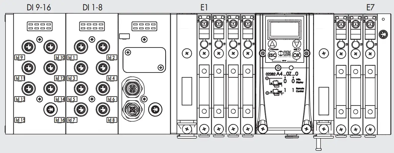
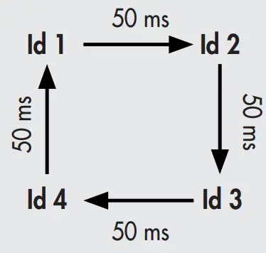
The system reads the data of each actuator cyclically and sequentially according to the update time set under Actuator Data Update Time.
The actuator number to which the values refer is indicated by the actuator ID byte. A short time, e.g. 50 ms, must be set to get readings in real time.
Actuator Id: indicating the actuator which the data read cyclically and sequentially refer to. Up to 10 actuator modules can be installed in the system. If, for instance, 4 actuator modules are installed, with an update time of 50 ms, the actuator ID rotates cyclically at 50 ms intervals, which means that the data of each actuator is updated every 200 ms.
State: if the values read exceed the times set in the “Tolerance” fields, the corresponding signalling bits activate and reset at the next reading with values within the tolerance.
- bit 0: actuation delay signal due to out of tolerance
- bit 1: reset delay signal due to out of tolerance
- bit 2: actuation time signal due to out of tolerance
- bit 3: return time signal due to out of tolerance
Actuator stroke counter: showing the number of actuations and reset movements of the actuator.
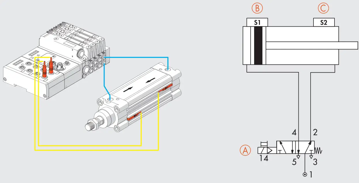
Example
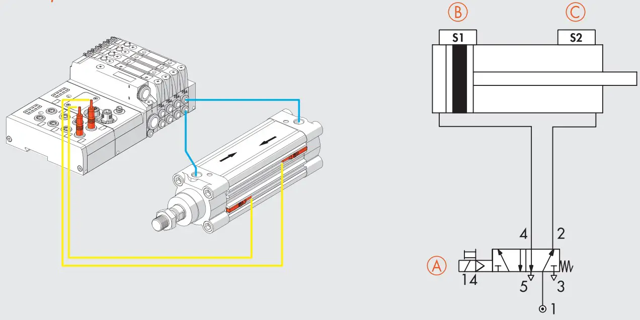
A = Valve in use, 5/2 one-pilot valve, pilot position on a base for two pilots = 7
B = Actuator return sensor – connected to input no. 8
C = Actuator extension sensor – connected to input no. 7
Pilot Id 1 = 7
Pilot Id 2 = 0
Limit switch input Id 1 = 8
Limit switch Input Id 2 = 7
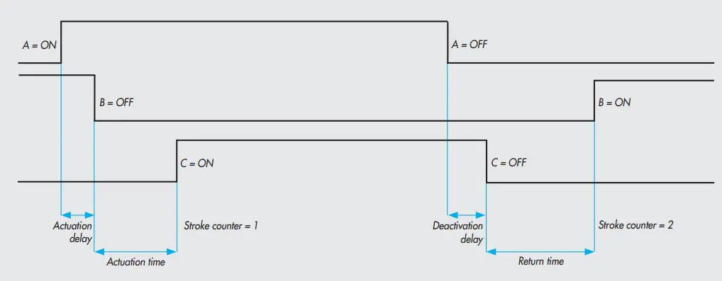
Actuator extension:
A – ON → B – OFF = Actuation delay
B – OFF → C – ON = Actuation time
Actuator return:
A – OFF → C – OFF = Deactivation delay
C – OFF → B – ON = Return time
All data is updated when actuator ID is equal to 7.
| Settings | Time read [ms] | Signalling bit | ||
| Function | Time [ms] | Tolerance | ||
| Actuation delay | 50 | ± 50 % (25 to 75 ms) | 54 | Off |
| 77 | On | |||
| Actuation time | 600 | ± 20 % (480 to 720 ms) | 610 | Off |
| 470 | On | |||
| Deactivation delay | 100 | ± 25 % (75 to 125 ms) | 120 | Off |
| 130 | On | |||
| Return time | 700 | ± 10 % (630 to 770 ms) | 650 | Off |
| 610 | On | |||
Assigning parameters
Object: No.1 Actuator
| Parameter | Function | Default value | Default |
| Par1 | Virtual module (for future use) | 0 | – |
| Par2 | Id electropilot 1 | 0 | No electropilot |
| Par3 | Id electropilot 2 | 0 | No electropilot |
| Par4 | Id FC1 | 0 | No limit switch |
| Par5 | Id FC2 | 0 | No limit switch |
| Par6 | Forward activation delay (MSB) | 0 | 0 ms |
| Par7 | Forward activation delay (LSB) | 0 | |
| Par8 | Tolerance of forward activation delay % (1…15) | 0 | 0 % |
| Par9 | Backward activation delay (MSB) | 0 | 0 ms |
| Par10 | Backward activation delay (LSB) | 0 | |
| Par11 | Tolerance of backward activation delay (1…15) | 0 | 0 % |
| Par12 | Actuator movement time (Byte4) | 0 | 0 ms |
| Par13 | Actuator movement time (Byte3) | 0 | |
| Par14 | Actuator movement time (Byte2) | 0 | |
| Par15 | Actuator movement time (Byte1) | 0 | |
| Par16 | Tolerance of actuator movement time (1…15) | 0 | 0 % |
| Par17 | Actuator return time (Byte4) | 0 | 0 ms |
| Par18 | Actuator return time (Byte3) | 0 | |
| Par19 | Actuator return time (Byte2) | 0 | |
| Par20 | Actuator return time (Byte1) | 0 | |
| Par21 | Tolerance of actuator return time (1…15) | 0 | 0 % |
Assignment of diagnosis addresses
| N° WORD | Dimensions [WORD] | ||
| System data | |||
| Counter switching | 66; 67 | 2 | |
| Power alarm counter (byte1, byte 2 Reserved) | 68 | 1 | |
| Valve data | |||
| Valve ID (the ID of the pressure regulators is subsequent to the last valve installed) | 69 | 1 | |
| Pressure Regulator | 70 | 1 | |
| Pilot 1 | Average life excess signal – bit 0 | 71 | 1 |
| Short-circuit alarm counter | 72 | 1 | |
| Circuit open alarm counter | 73 | 1 | |
| Cycle counter | 74; 75 | 2 | |
| Counter of total pilot 1 energising time [sec] – operating hour meter of pressure regulator | 76; 77 | 2 | |
| Pilot 2 | Average life excess signal – bit 0 | 78 | 1 |
| Short-circuit alarm counter | 79 | 1 | |
| Circuit open alarm counter | 80 | 1 | |
| Cycle counter | 81; 82 | 2 | |
| Counter of total pilot 2 energising time [sec] | 83; 84 | 2 | |
| Actuator data | |||
| Actuator Id | 85 | 1 | |
| State | 86 | 1 | |
| Actuation delay [ms] | 87 | 1 | |
| Reset delay [ms] | 88 | 1 | |
| Actuation time [ms] | 89; 90 | 2 | |
| Return time [ms] | 91; 92 | 2 | |
| Actuator stroke counter | 93; 94 | 2 | |
| Reserved | 95 | 1 | |
Assignment of diagnosis addresses – byte management
| N° byte | Dimensions [byte] | ||
| System data | |||
| Counter switching | from 132 to 135 | 4 | |
| Power alarm counter | 136 | 1 | |
| Reserved | 137 | 1 | |
| Valve data | |||
| Valve ID (the ID of the pressure regulators is subsequent to the last valve installed) | 138; 139 | 1 | |
| Pressure Regulator | 140; 141 | 1 | |
| Pilot 1 | Average life excess signal – bit 0 | 142; 143 | 1 |
| Short-circuit alarm counter | 144; 145 | 1 | |
| Circuit open alarm counter | 146; 147 | 1 | |
| Cycle counter | from 148 to 151 | 2 | |
| Counter of total pilot 1 energising time [sec] – operating hour meter of pressure regulator | from 152 to 155 | 2 | |
| Pilot 2 | Average life excess signal – bit 0 | 156; 157 | 2 |
| Short-circuit alarm counter | 158; 159 | 2 | |
| Circuit open alarm counter | 160; 161 | 2 | |
| Cycle counter | from 162 to 165 | 4 | |
| Counter of total pilot 2 energising time [sec] | from 166 to 169 | 4 | |
| Actuator data | |||
| Actuator Id | 170; 171 | 2 | |
| State | 172; 173 | 2 | |
| Actuation delay [ms] | 174; 175 | 2 | |
| Reset delay [ms] | 176; 177 | 2 | |
| Actuation time [ms] | from 178 to 181 | 4 | |
| Return time [ [ms] | from 182 to 185 | 4 | |
| Actuator stroke counter | from 186 to 189 | 4 | |
| Reserved | 190; 191 | 2 | |
Example of configuration of the times
| ms time | Value Dec | Value Hex | Hex (MSB) | Hex (LSB) | Dec (MSB) | Dec (LSB) |
| 1200 | 1200 | 04B0 | 04 | B0 | 4 | 176 |
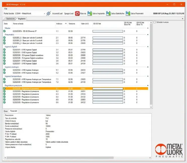
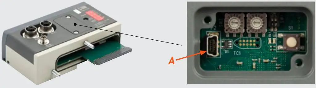
DATA READING USING THE EB 80 Manager SOFTWARE
The EB 80 Manager software is used to read data directly from the EB 80 power connection with fieldbus, via the USB port (A) located under the power connection cover.
Connecting the EB 80 to the PC. Open the EB 80 Manager software.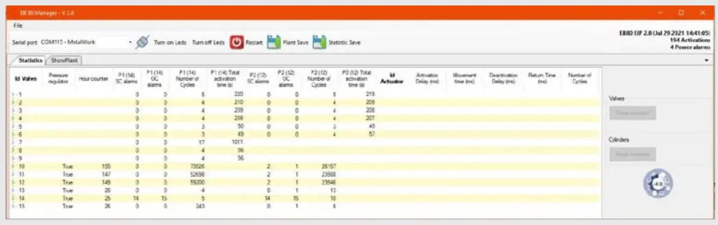
Select the serial port: COMx-MetalWork and connect up to the system by clicking on the connection icon.
The data of all the valves, of pressure Regulators and configured actuators will be displayed.
Data reset of valves
When a valve is replaced, it is advisable to reset the number of cycles. To do this, select the valve to be reset and click on the “Valves – Reset Selected” button. The data of the first row will be reset and saved in another non-resettable memory area, which can be viewed by clicking on the arrow of the tree menu.
In this way, the “relative” data of the valve being used and the “absolute” data of the system are available. At each reset, the relative data is added to the absolute data.
Data reset of actuators
When an actuator is replaced, it is advisable to reset the number of strokes. To do this, select the actuator to be reset and click on the “Actuators – Reset Selected” button. The actuator data will be reset.
To restore the system after disconnection, turn the system off and then on again.
Display of the set parameters
By selecting the module, in the “parameters” tab the parameters settings are displayed.