LSI 4SQ Steel Poles Square Straight User Guide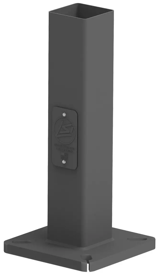
FEATURES & SPECIFICATIONS
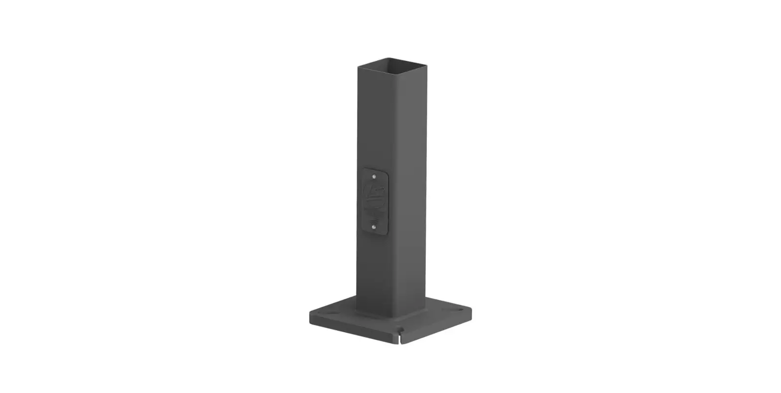
Pole Shaft
- Straight poles are 4”, 5”, or 6” square.
- Pole shaft is electro-welded ASTM-A500 Grade C steel tubing with a minimum yield strength of 50,000 psi.
- On Tenon Mount steel poles, tenon is 2-3/8” O.D. high-strength pipe. Tenon is 4-3/4” in length.
Hand-Hole
- Standard hand-hole location is 12” above pole base.
- Poles 22’ and above have a 3” x 6” reinforced hand-hole. Shorter poles have a 2” x 4” non-reinforced hand-hole.
Base
- Pole base is ASTM-A36 hot-rolled steel plate with a minimum yield strength of 36,000 psi.
- Two-piece square base cover is optional.
Anchor Bolts
- Poles are furnished with anchor bolts featuring zinc-plated double nuts and washers. Galvanized anchor bolts are optional.
- Anchor Bolts conform to ASTM F 1554-07a Grade 55 with a minimum yield strength of 55,000 PSI.
Ground Lug
- Ground lug is standard.
Duplex Receptacle
- Weatherproof duplex receptacle is optional.
Ground Fault Circuit Interrupter
- Self-testing Ground fault circuit interrupter is optional.
Finishes
- Every pole is provided with the DuraGrip Protection System and a 5-year limited warranty:
- When the top-of-the line DuraGrip Plus Protection System is selected, in addition to the DuraGrip Protection System, a nonporous, automotive-grade corrosion coating is applied to the lower portion of the pole interior sealing and further protecting it from corrosion. This option extends the limited warranty to 7 years.
Determining The Luminaire/Pole Combination For Your Application:
- Select luminaire from luminaire ordering information.
- Select bracket configuration if required
- Determine EPA value from luminaire/ bracket EPA chart
- Select Pole Height
- Select MPH to match wind speed in the application area (See windspeed maps).
- Confirm pole EPA equal to or exceeding value of luminaire/bracket EPA
- Consult factory for special wind load requirements and banner brackets.
Pole Vibration Damper
- A pole vibration damper is recommended in open terrain areas of the country where low steady state winds are common.
- Non-tapered poles and lightly loaded poles are more susceptible to destructive vibration if a damper is not installed.
Listings
- UL Listed
- BAA/TAA Compliant
ORDERING GUIDE
| Pole Series | Mounting Method | Material | Height 2 | Mounting Configuration | Pole Finish | Options |
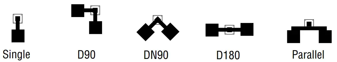
| 4SQ – 4” x 4” Square Straight Pole (New Build) 5SQ – 5” x 5” Square Straight Pole (New Build) 6SQ – 6” x 6” Square Straight Pole (New Build) 4SQU – 4” x 4” Square Straight Pole (Retrofit) 5SQU – 5” x 5” Square Straight Pole (Retrofit) 6SQU – 6” x 6” Square Straight Pole (Retrofit) | Bolt-On Mount1 – See pole selection guide for patterns and fixture matches. B5 – 5” Traditional Drilling Pattern B3 – 3” Reduced Drilling Pattern B2 – 2” Reduced Drilling Pattern | S11G – 11 Ga. Steel (4SQ/4SQU and 5SQ/5SQU Only) S07G – 07 Ga. Steel | 8’ 10’ 12’ 13’ 14’ 15’ 16’ 17’ 17’ 6” 18’ 20’ 22’ 22’6” 23’ 24’ 25’ 26’ 27’ 28’ 30’ 32’ 35’ 39’ | S – Single/Parallel D180 – Double D90 – Double DN90 – Double T90 – Triple TN120 – Triple Q90 – Quad QN90 – Quad | BRZ – Bronze BLK – Black GPT – Graphite MSV – Metallic Silver | GA – Galvanized Anchor Bolts SF – Single Flood3 DF – Double Flood 3 DGP – DuraGrip® Plus LAB – Less Anchor Bolts CRXX – Conduit Raceway4 |
| N – Tenon Mount (Standard Tenon size is 2-3/8” O.D.)8 |
Accessory Ordering Information
| Description | Order Number |
| 4BC – 4″ Square Base Cover | 122559CLR |
| 5BC – 5″ Square Base Cover | 122561CLR |
| 6BC – 6” Square Base Cover | 122563CLR |
| ER2 – Weatherproof Duplex Receptacle | 122566CLR |
| GFI – Ground Fault Circuit Interrupter | 122567CLR |
| MH5 – mounting Hole Plugs for use with 5” traditional drill pattern (3 set of 3 plugs) | 132336 |
| MH3 – mounting Hole Plugs for use with 3” reduced drill pattern (3 set of 3 plugs) | 681126 |
| MH2 – Mounting Hole Plugs for use with 2” reduced drill pattern (3 sets of 3 plugs) | 725841 |
| Vibration Damper – 4″ Square Pole (bolt-on mount only) | 172539 |
| Vibration Damper – 5” Square Pole (bolt-on mount only) | 172538 |
| Vibration Damper – 6” Square Pole (bolt-on mount only) | 178361 |
FOOTNOTES:
- See Area Light Brackets – 3” Reduced Drill Pattern and Area Light Brackets – 5” Traditional Drill Pattern Spec Sheets.
- Pole heights will have +/- 1/2” tolerance.
- See Flood Lighting Brackets section for choice of FBO brackets.
- CR selection must indicate required height and side of pole mounting location. Mounting template required at time of order.
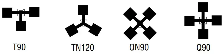
DRILLING LOCATIONS
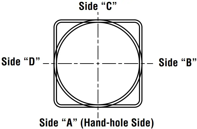
| Sides | A | B | C | D |
| Hand-hole | X | |||
| Single | X | |||
| D180 | X | X | ||
| D90 | X | X | ||
| DN901 | ||||
| T90 | X | X | X | |
| TN1202 | ||||
| Q90 | X | X | X | X |
| QN903 | ||||
| Single FBO | X | |||
| Double FBO | X | X |
NOTES:
- Two locations will be 45° to the left and right of Side A.
- Other two locations will be 120° to the left and right of Side A.
- Two locations will be 45° to the left and right of Side A and two locations will be 135° to the left and right of Side A.
Consult factory for custom variations. Standard SF and DF pole preparations are located 3/4 of the height of the pole from the base, except on 20’ poles. Maximum height for SF and DF pole preparations on 20’ poles is 13’ from the base.
FIXTURE CONFIGURATIONS
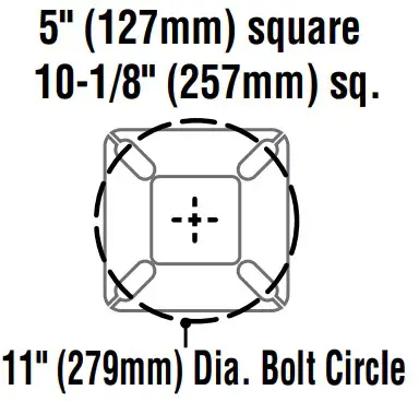
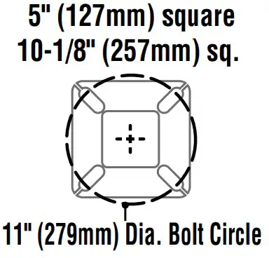
BOLT CIRCLE
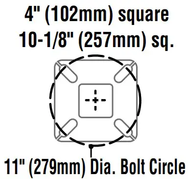 |  |  | 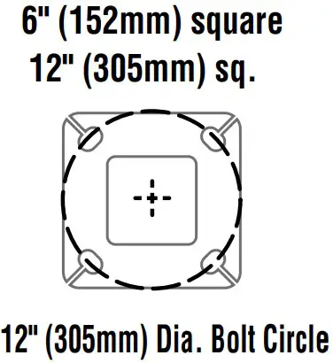 | |
| Bolt Circle Designator | B | C | D | J |
| Bolt Circle | Slotted8”-11″ (203mm-279mm) | Slotted9”-11″ (229mm-279mm) | Slotted9”-11″ (229mm-279mm) | Slotted 12″ (305mm) |
| Anchor Bolt Size | 3/4″ x 30″(19mm x 762mm) | 3/4″ x 30″(19mm x 762mm) | 1″ x 36″(25mm x 914mm) | 1″ x 36″(25mm x 914mm) |
| Anchor Bolt Projection | 3-1/4″(83mm) | 3-1/4″(83mm) | 4″ (102mm) | 4″ (102mm) |
| Base Plate Opening for Wireway Entry | 3-5/8″(92mm) | 4-3/4″ (121mm) | 4-5/8″ (117mm) | 5-5/8″ (143mm) |
| Base Plate Dimensions | 10-1/8″ sq. x 3/4″ thk. (257mm x 19mm) | 10-1/8″ sq. x 3/4″ thk. (257mm x 19mm) | 10-1/8″ sq. x 1″ thk. (257mm x 25mm) | 12″ sq. x 1-1/8″ thk. (305mm x 29mm) |
| Pole Gauge | 11 | 11 | 7 | 7 |
Note: Base plate illustrations may change without notice. Do not use for setting anchor bolts. Consult factory for the appropriate anchor bolt template.
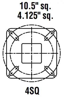 | 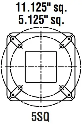 | 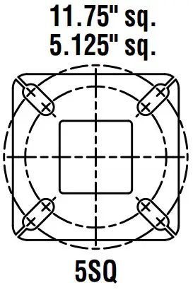 | 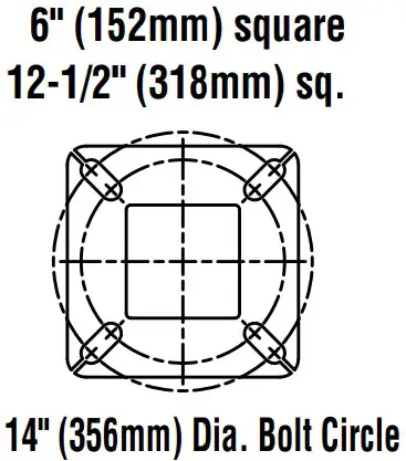 | |
| Bolt Circle Designator | E | F | G | H |
| Bolt Circle | Slotted 9″-12″ | Slotted 10-13″ | Slotted 10-13″ | Slotted11”-14″ (279mm-356mm) |
| Anchor Bolt Size | 3/4″ x 30″(19mm x 762 mm) | 3/4x 30″(25mm x 914 mm) | 1x 36″(25mm x 914 mm) | 1″ x 36″(25mm x 914mm) |
| Anchor Bolt Projection | 3-1/4″(83 mm) | 3-1/4″(83 mm) | 4″(102 mm) | 4″ (102mm) |
| Base Plate Opening for Wireway Entry | 4-1/8″ (105 mm) | 5-1/8″ (130 mm) | 5-1/8″ (130 mm) | 6-1/8″ (156mm) |
| Base Plate Dimensions | 10-1/2″ sq. x 3/4″ thk. (267 mm x 19 mm) | 11-1/8 sq. x 3/4″ thk. (283 mm x 19 mm) | 11-3/4″ sq. x 1″ thk. (298 mm x 25 mm) | 12 1/2″ sq. x 1 1/8″ thk. (318mm x 29mm) |
| Pole Gauge | 11 | 11 | 7 | 7 |
Note: Base plate illustrations may change without notice. Do not use for setting anchor bolts. Consult factory for the appropriate anchor bolt template.
PRODUCT DIMENSIONS
SQT – N= 2-3/8″ (60mm) O.D. x 4-3/4″ (121mm) Tenon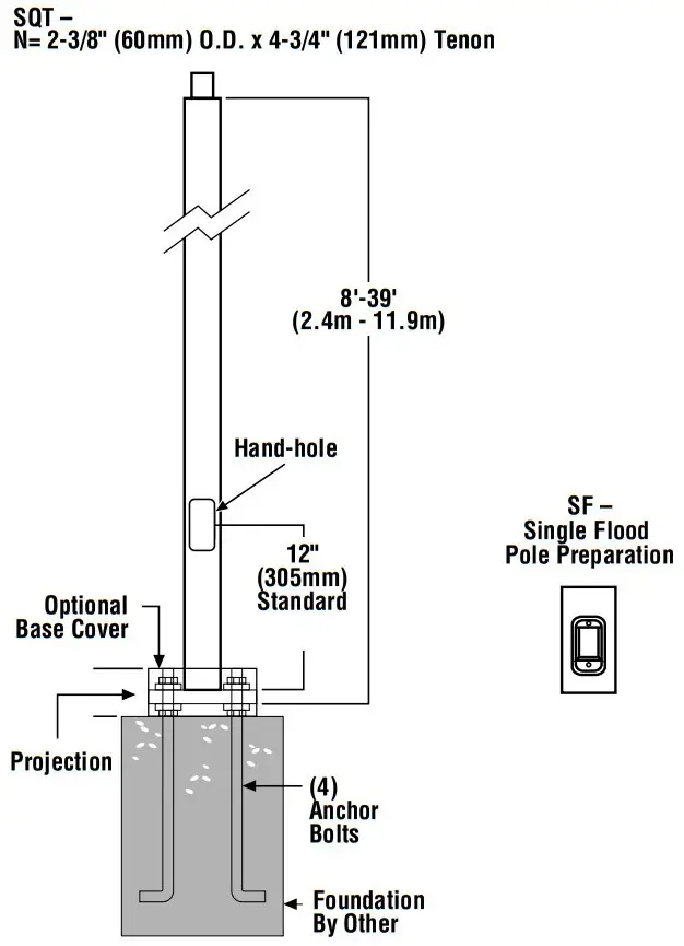
| SHIPPING WEIGHTS | |
| 4”(102mm) sq. 11 Ga. is approximately | 7.50 lbs./ft. |
| 4”(102mm) sq. 07 Ga. is approximately | 10.00 lbs./ft. |
| 5”(127mm) sq. 11 Ga. is approximately | 9.00 lbs./ft. |
| 5”(127mm) sq. 07 Ga. is approximately | 12.50 lbs./ft. |
| 6”(152mm) sq. 07 Ga. is approximately | 15.40 lbs./ft. |
| Anchor Bolts (3/4” x 30”)(19mm x 762mm) | 15 lbs. (7kg)/set |
| Anchor Bolts (1” x 36”)(25mm x 914mm) | 30 lbs. (14kg)/set |
Bolt-On Mount 2-Bolt Pattern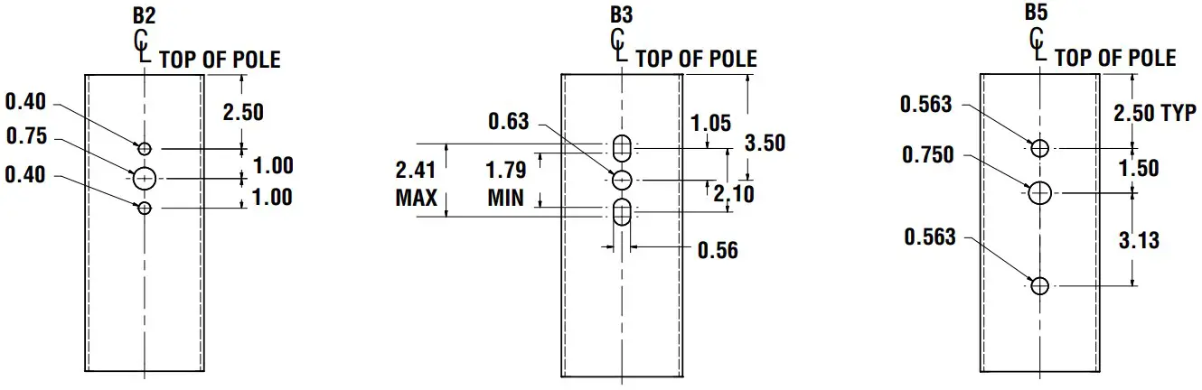
WIND SPEED
EPA Information
All LSI Industries’ poles are guaranteed to meet the EPA requirements listed. LSI Industries is not responsible if a pole order has a lower EPA rating than the indicated wind-loading zone where the pole will be located.
CAUTION: This guarantee does not apply if the pole/bracket/fixture combination is used to support any other items such as flags, pennants, or signs, which would add stress to the pole. LSI Industries cannot accept responsibility for harm or damage caused in these situations.
NOTE: Pole calculations include a 1.3 gust factor over steady wind velocity. Example: poles designed to withstand 80 MPH steady wind will withstand gusts to 104 MPH. EPAs are for locations 100 miles away from hurricane ocean lines. Consult LSI for other areas. Note: Hurricane ocean lines are the Atlantic and Gulf of Mexico coastal areas. For applications in Florida or Canada, consult factory.
Use ONLY with “Wind Speed Map for ASCE 7-10
| POLE1 | Mtg. Height Length(ft) | Wall Thick (ga) | BOLT CIRCLE | EPA | ||||||||||
| Designator | Dia. (in) | Anchor bolt Dia {in} | 110 MPH | 115 MPH | 120 MPH | 130 MPH | 140 MPH | 150 MPH | 160 MPH | 170 MPH | 180 MPH | |||
| 4” x 11-ga x 12’ | 12 | 11 | B | 8″ – 11″ | 0.75 | 13.9 | 12.5 | 11.3 | 9.2 | 7.6 | 6.3 | 5.2 | 4.3 | 3.6 |
| 4” x 11-ga x 14’ | 14 | 11 | B | 8″ – 11″ | 0.75 | 10.7 | 9.5 | 8.5 | 6.8 | 5.4 | 4.4 | 3.5 | 2.7 | 2.1 |
| 4” x 11-ga x 16’ | 16 | 11 | B | 8″ – 11″ | 0.75 | 8.2 | 7.2 | 6.4 | 4.9 | 3.8 | 2.9 | 2.1 | 1.5 | 1.0 |
| 4” x 11-ga x 18’ | 18 | 11 | B | 8″ – 11″ | 0.75 | 6.3 | 5.4 | 4.7 | 3.4 | 2.4 | 1.6 | 1.0 | 0.4 | n/a |
| 4” x 11-ga x 20’ | 20 | 11 | B | 8″ – 11″ | 0.75 | 4.6 | 3.9 | 3.2 | 2.1 | 1.2 | 0.6 | n/a | n/a | n/a |
| 4” x 11-ga x 22’ | 22 | 11 | B | 8″ – 11″ | 0.75 | 7.6 | 6.6 | 5.7 | 4.2 | 3.0 | 2.0 | 1.2 | 0.5 | n/a |
| 4” x 11-ga x 24’ | 24 | 11 | B | 8″ – 11″ | 0.75 | 6.0 | 5.1 | 4.3 | 2.9 | 1.8 | 0.9 | n/a | n/a | n/a |
| 4” x 11-ga x 26’ | 26 | 11 | B | 8″ – 11″ | 0.75 | 4.6 | 3.7 | 3.0 | 1.7 | 0.7 | n/a | n/a | n/a | n/a |
| 4” x 7-ga x 14’ | 14 | 7 | B | 8″ – 11″ | 0.75 | 18.3 | 16.4 | 14.9 | 12.2 | 10.2 | 8.5 | 7.1 | 5.9 | 5.0 |
| 4” x 7-ga x 16’ | 16 | 7 | B | 8″ – 11″ | 0.75 | 14.7 | 13.2 | 11.8 | 9.6 | 7.8 | 6.3 | 5.2 | 4.2 | 3.4 |
| 4” x 7-ga x 18’ | 18 | 7 | B | 8″ – 11″ | 0.75 | 11.9 | 10.5 | 9.3 | 7.4 | 5.9 | 4.6 | 3.6 | 2.8 | 2.1 |
| 4” x 7-ga x 20’ | 20 | 7 | B | 8″ – 11″ | 0.75 | 9.6 | 8.4 | 7.4 | 5.7 | 4.3 | 3.2 | 2.3 | 1.6 | 0.9 |
| 4” x 7-ga x 22’ | 22 | 7 | B | 8″ – 11″ | 0.75 | 7.7 | 6.6 | 5.7 | 4.2 | 3.0 | 2.0 | 1.2 | 0.5 | n/a |
| 4” x 7-ga x 24’ | 24 | 7 | B | 8″ – 11″ | 0.75 | 6.0 | 5.1 | 4.3 | 2.9 | 1.8 | 0.9 | n/a | n/a | n/a |
| 4″ x 7-ga x 26′ | 26 | 7 | B | 8″ – 11″ | 0.75 | 4.6 | 3.7 | 3.0 | 1.7 | 0.7 | n/a | n/a | n/a | n/a |
| 4” x 7-ga x 28’2 | 28 | 7 | B | 8″ – 11″ | 0.75 | 3.3 | 2.5 | 1.8 | 0.7 | n/a | n/a | n/a | n/a | n/a |
| 4” x 7-ga x 30’2 | 30 | 7 | B | 8″ – 11″ | 0.75 | 2.2 | 1.4 | 0.8 | n/a | n/a | n/a | n/a | n/a | n/a |
| 5” x 11-ga x 14’ | 14 | 11 | C | 9” – 11” | 0.75 | 17.4 | 15.7 | 14.1 | 11.5 | 9.3 | 7.7 | 6.3 | 5.2 | 4.2 |
| 5” x 11-ga x 16’ | 16 | 11 | C | 9” – 11” | 0.75 | 13.8 | 12.3 | 10.9 | 8.7 | 6.9 | 5.5 | 4.3 | 3.3 | 2.5 |
| 5” x 11-ga x 18’ | 18 | 11 | C | 9” – 11” | 0.75 | 10.8 | 9.6 | 8.4 | 6.5 | 4.9 | 3.7 | 2.6 | 1.8 | 1.1 |
| 5” x 11-ga x 20’ | 20 | 11 | C | 9” – 11” | 0.75 | 8.5 | 7.3 | 6.3 | 4.6 | 3.2 | 2.1 | 1.2 | 0.5 | n/a |
| 5” x 11-ga x 22’ | 22 | 11 | C | 9” – 11” | 0.75 | 10.9 | 9.5 | 8.3 | 6.2 | 4.5 | 3.2 | 2.1 | 1.2 | 0.5 |
| 5” x 11-ga x 24’ | 24 | 11 | C | 9” – 11” | 0.75 | 8.8 | 7.5 | 6.4 | 4.5 | 3.0 | 1.8 | 0.8 | n/a | n/a |
| 5” x 11-ga x 26’ | 26 | 11 | C | 9” – 11” | 0.75 | 6.8 | 5.7 | 4.6 | 3.0 | 1.6 | 0.6 | n/a | n/a | n/a |
| 5” x 11-ga x 28’ | 28 | 11 | C | 9” – 11” | 0.75 | 5.2 | 4.1 | 3.2 | 1.6 | 0.4 | n/a | n/a | n/a | n/a |
| 5” x 11-ga x 30’ | 30 | 11 | C | 9” – 11” | 0.75 | 3.6 | 2.7 | 1.8 | 0.4 | n/a | n/a | n/a | n/a | n/a |
| 5” x 7-ga x 20’ | 20 | 7 | D | 9” – 11” | 1.00 | 21.6 | 19.3 | 17.3 | 14.0 | 11.3 | 9.2 | 7.4 | 6.0 | 4.8 |
| 5” x 7-ga x 22’ | 22 | 7 | D | 9” – 11” | 1.00 | 20.7 | 18.6 | 16.6 | 13.3 | 10.7 | 8.5 | 6.8 | 5.4 | 4.2 |
| 5” x 7-ga x 24’ | 24 | 7 | D | 9” – 11” | 1.00 | 17.7 | 15.6 | 13.8 | 10.8 | 8.5 | 6.6 | 5.0 | 3.7 | 2.6 |
| 5″ x 7-ga x 26′ | 26 | 7 | D | 9” – 11” | 1.00 | 14.9 | 13.1 | 11.4 | 8.8 | 6.6 | 4.9 | 3.5 | 2.3 | 1.3 |
| 5” x 7-ga x 28’ | 28 | 7 | D | 9” – 11” | 1.00 | 12.5 | 10.9 | 9.4 | 6.9 | 4.9 | 3.4 | 2.1 | 1.0 | n/a |
| 5” x 7-ga x 30’ | 30 | 7 | D | 9” – 11” | 1.00 | 10.3 | 8.9 | 7.5 | 5.2 | 3.4 | 2.0 | 0.8 | n/a | n/a |
| 5” x 7-ga x 35’ | 35 | 7 | D | 9” – 11” | 1.00 | 6.0 | 4.8 | 3.6 | 1.8 | n/a | n/a | n/a | n/a | n/a |
| 6” x 7-ga x 24’ | 24 | 7 | J | 12″ | 1.00 | 18.6 | 16.4 | 14.3 | 11.2 | 8.6 | 6.5 | 4.8 | 3.4 | 2.2 |
| 6” x 7-ga x 26’ | 26 | 7 | J | 12″ | 1.00 | 15.6 | 13.4 | 11.7 | 8.8 | 6.5 | 4.6 | 3.0 | 1.8 | 0.7 |
| 6” x 7-ga x 28’ | 28 | 7 | J | 12″ | 1.00 | 12.9 | 10.9 | 9.3 | 6.7 | 4.6 | 2.8 | 1.5 | n/a | n/a |
| 6” x 7-ga x 30’ | 30 | 7 | J | 12″ | 1.00 | 10.4 | 8.8 | 7.3 | 4.8 | 2.9 | 1.3 | n/a | n/a | n/a |
| 6” x 7-ga x 32’ | 32 | 7 | J | 12″ | 1.00 | 8.3 | 6.8 | 5.5 | 3.1 | 1.3 | n/a | n/a | n/a | n/a |
| 6” x 7-ga x 34’ | 34 | 7 | J | 12″ | 1.00 | 6.5 | 5.0 | 3.7 | 1.6 | n/a | n/a | n/a | n/a | n/a |
| 6” x 7-ga x 35’ | 35 | 7 | J | 12″ | 1.00 | 5.5 | 4.2 | 2.9 | 0.9 | n/a | n/a | n/a | n/a | n/a |
| 6” x 7-ga x 39’ | 39 | 7 | J | 12″ | 1.00 | 2.3 | 1.0 | n/a | n/a | n/a | n/a | n/a | n/a | n/a |
All LSI Industries’ poles are guaranteed to meet the EPA requirements listed. LSI Industries is not responsible if a pole order has a lower EPA rating than the indicated wind-loading zone where the pole will be located.
CAUTION: This guarantee does not apply if the pole/bracket/fixture combination is used to support any other items such as flags, pennants, or signs, which would add stress to the pole. LSI Industries cannot accept responsibility for harm or damage caused in these situations.
Note:
- Poles shorter than these listed here in for each gauge have EPA rating equal to or greater than what is provided in this table. To Confirm EPA ratings on shorter poles, contact LSI Industries.
- LSI Industries recommends a vibration damper be ordered with this length.
| POLE1 | Mtg. Height Length(ft) | Wall Thick (ga) | BOLT CIRCLE | EPA | ||||||||||
| Designator | Dia. (in) | Anchor bolt Dia {in} | 110 MPH | 115 MPH | 120 MPH | 130 MPH | 140 MPH | 150 MPH | 160 MPH | 170 MPH | 180 MPH | |||
| 5″ x 11-ga x 14′ | 14 | 11 | F | 11″ | 0.75 | 17.6 | 15.8 | 14.2 | 11.5 | 9.4 | 7.7 | 6.3 | 5.2 | 4.3 |
| 5″ x 11-ga x 14′ | 14 | 11 | F | 13″ | 0.75 | 17.6 | 15.8 | 14.2 | 11.5 | 9.4 | 7.7 | 6.3 | 5.2 | 4.3 |
| 5″ x 11-ga x 16′ | 16 | 11 | F | 11″ | 0.75 | 13.9 | 12.2 | 11.0 | 8.8 | 7.0 | 5.5 | 4.3 | 3.4 | 2.5 |
| 5″ x 11-ga x 16′ | 16 | 11 | F | 13″ | 0.75 | 13.9 | 12.2 | 11.0 | 8.8 | 7.0 | 5.5 | 4.3 | 3.4 | 2.5 |
| 5″ x 11-ga x 18′ | 18 | 11 | F | 11″ | 0.75 | 11.0 | 9.6 | 8.4 | 6.5 | 5.0 | 3.7 | 2.7 | 1.8 | 1.1 |
| 5″ x 11-ga x 18′ | 18 | 11 | F | 13″ | 0.75 | 11.0 | 9.6 | 8.4 | 6.5 | 5.0 | 3.7 | 2.7 | 1.8 | 1.1 |
| 5″ x 11-ga x 20′ | 20 | 11 | F | 11″ | 0.75 | 8.6 | 7.4 | 6.4 | 4.6 | 3.3 | 2.2 | 1.3 | 0.5 | – |
| 5″ x 11-ga x 20′ | 20 | 11 | F | 13″ | 0.75 | 8.6 | 7.4 | 6.4 | 4.6 | 3.3 | 2.2 | 1.3 | 0.5 | – |
| 5″ x 11-ga x 22′ | 22 | 11 | F | 11″ | 0.75 | 12.7 | 11.1 | 9.6 | 7.4 | 5.6 | 4.1 | 3.0 | 2.0 | 1.1 |
| 5″ x 11-ga x 22′ | 22 | 11 | F | 12″ | 0.75 | 10.3 | 8.9 | 7.7 | 5.7 | 4.1 | 2.8 | 1.8 | 0.9 | – |
| 5″ x 11-ga x 22′ | 22 | 11 | F | 13″ | 0.75 | 8.6 | 7.4 | 6.4 | 4.6 | 3.1 | 2.0 | 1.1 | – | – |
| 5″ x 11-ga x 24′ | 24 | 11 | F | 11″ | 0.75 | 10.2 | 8.9 | 7.6 | 5.6 | 4.0 | 2.6 | 1.6 | 0.7 | – |
| 5″ x 11-ga x 24′ | 24 | 11 | F | 12″ | 0.75 | 8.0 | 6.9 | 5.8 | 4.0 | 2.6 | 1.5 | 0.5 | – | – |
| 5″ x 11-ga x 24′ | 24 | 11 | F | 13″ | 0.75 | 6.7 | 5.5 | 4.6 | 3.0 | 1.7 | 0.7 | – | – | – |
| 5″ x 11-ga x 26′ | 26 | 11 | F | 11″ | 0.75 | 8.1 | 6.9 | 5.8 | 4.0 | 2.5 | 1.3 | – | – | – |
| 5″ x 11-ga x 26′ | 26 | 11 | F | 12″ | 0.75 | 6.2 | 5.1 | 4.1 | 2.6 | 1.3 | – | – | – | – |
| 5″ x 11-ga x 26′ | 26 | 11 | F | 13″ | 0.75 | 5.0 | 4.0 | 3.1 | 1.6 | 0.5 | – | – | – | – |
| 5″ x 11-ga x 28′ | 28 | 11 | F | 11″ | 0.75 | 6.3 | 5.2 | 4.3 | 2.5 | 1.1 | – | – | – | – |
| 5″ x 11-ga x 28′ | 28 | 11 | F | 12″ | 0.75 | 4.6 | 3.6 | 2.7 | 1.2 | – | – | – | – | – |
| 5″ x 11-ga x 28′ | 28 | 11 | F | 13″ | 0.75 | 3.4 | 2.5 | 1.7 | – | – | – | – | – | – |
| 5″ x 11-ga x 30′ | 30 | 11 | F | 11″ | 0.75 | 4.7 | 3.7 | 2.8 | 1.2 | – | – | – | – | – |
| 5″ x 11-ga x 30′ | 30 | 11 | F | 12″ | 0.75 | 3.1 | 2.2 | 1.4 | – | – | – | – | – | – |
| 5″ x 11-ga x 30′ | 30 | 11 | F | 13″ | 0.75 | 2.0 | 1.2 | 0.5 | – | – | – | – | – | – |
| 5″ x 7-ga x 20′ | 20 | 7 | G | 11″ | 0.75 | 19.0 | 17.0 | 15.0 | 12.2 | 9.7 | 7.8 | 6.2 | 5.0 | 3.8 |
| 5″ x 7-ga x 20′ | 20 | 7 | G | 12″ | 0.75 | 21.4 | 19.1 | 17.1 | 13.8 | 11.2 | 9.1 | 7.3 | 5.9 | 4.7 |
| 5″ x 7-ga x 20′ | 20 | 7 | G | 13″ | 0.75 | 21.4 | 19.2 | 17.2 | 13.9 | 11.3 | 9.2 | 7.4 | 6.0 | 4.8 |
| 5″ x 7-ga x 20′ | 20 | 7 | G | 11″ | 1 | 21.7 | 19.4 | 17.4 | 14.0 | 11.4 | 9.3 | 7.5 | 6.0 | 4.8 |
| 5″ x 7-ga x 20′ | 20 | 7 | G | 13″ | 1 | 21.7 | 19.4 | 17.4 | 14.0 | 11.4 | 9.3 | 7.5 | 6.0 | 4.8 |
| 5″ x 7-ga x 22′ | 22 | 7 | G | 11″ | 0.75 | 16.0 | 14.1 | 12.5 | 9.8 | 7.6 | 5.9 | 4.4 | 3.3 | 2.3 |
| 5″ x 7-ga x 22′ | 22 | 7 | G | 12″ | 0.75 | 17.7 | 15.9 | 14.2 | 11.2 | 8.7 | 7.0 | 5.4 | 4.1 | 3.0 |
| 5″ x 7-ga x 22′ | 22 | 7 | G | 13″ | 0.75 | 19.9 | 17.3 | 15.6 | 12.6 | 10.0 | 8.0 | 6.3 | 5.0 | 3.8 |
| 5″ x 7-ga x 22′ | 22 | 7 | G | 11″ | 1 | 21.0 | 18.7 | 16.7 | 13.4 | 10.6 | 8.5 | 6.8 | 5.4 | 4.2 |
| 5″ x 7-ga x 22′ | 22 | 7 | G | 12″ | 1 | 23.4 | 20.6 | 18.4 | 15.0 | 12.2 | 9.9 | 8.0 | 6.4 | 5.1 |
| 5″ x 7-ga x 22′ | 22 | 7 | G | 13″ | 1 | 21.3 | 18.8 | 17.0 | 13.7 | 11.0 | 8.8 | 7.0 | 5.6 | 4.3 |
| 5″ x 7-ga x 24′ | 24 | 7 | G | 11″ | 0.75 | 13.3 | 11.6 | 10.0 | 7.7 | 5.7 | 4.2 | 2.9 | 1.9 | 1.0 |
| 5″ x 7-ga x 24′ | 24 | 7 | G | 12″ | 0.75 | 15.0 | 13.0 | 11.6 | 8.9 | 6.8 | 5.1 | 3.8 | 2.6 | 1.7 |
| 5″ x 7-ga x 24′ | 24 | 7 | G | 13″ | 0.75 | 16.6 | 14.6 | 12.9 | 10.2 | 8.0 | 6.1 | 4.6 | 3.3 | 2.3 |
| 5″ x 7-ga x 24′ | 24 | 7 | G | 11″ | 1 | 17.5 | 15.7 | 13.9 | 10.9 | 8.6 | 6.7 | 5.0 | 3.7 | 2.7 |
| 5″ x 7-ga x 24′ | 24 | 7 | G | 12″ | 1 | 20.0 | 17.4 | 15.4 | 12.3 | 9.9 | 7.8 | 6.0 | 4.7 | 3.5 |
| 5″ x 7-ga x 24′ | 24 | 7 | G | 13″ | 1 | 18.1 | 16.0 | 14.2 | 11.0 | 8.7 | 6.7 | 5.3 | 3.9 | 2.8 |
| 5″ x 7-ga x 26′ | 26 | 7 | G | 11″ | 0.75 | 10.9 | 9.3 | 8.0 | 5.9 | 4.1 | 2.7 | 1.6 | 0.6 | – |
| 5″ x 7-ga x 26′ | 26 | 7 | G | 12″ | 0.75 | 12.4 | 10.9 | 9.5 | 7.0 | 5.1 | 3.6 | 2.3 | 1.3 | – |
| 5″ x 7-ga x 26′ | 26 | 7 | G | 13″ | 0.75 | 14.0 | 12.3 | 10.7 | 8.1 | 6.0 | 4.4 | 3.1 | 2.0 | 1.0 |
| 5″ x 7-ga x 26′ | 26 | 7 | G | 11″ | 1 | 15.0 | 13.2 | 11.5 | 8.8 | 6.7 | 4.9 | 3.5 | 2.3 | 1.3 |
| POLE1 | Mtg. Height Length(ft) | Wall Thick (ga) | BOLT CIRCLE | EPA | ||||||||||
| Designator | Dia. (in) | Anchor bolt Dia {in} | 110 MPH | 115 MPH | 120 MPH | 130 MPH | 140 MPH | 150 MPH | 160 MPH | 170 MPH | 180 MPH | |||
| 5″ x 7-ga x 26′ | 26 | 7 | G | 12″ | 1 | 17.0 | 14.8 | 13.0 | 10.2 | 7.9 | 6.0 | 4.4 | 3.1 | 2.1 |
| 5″ x 7-ga x 26′ | 26 | 7 | G | 13″ | 1 | 15.3 | 13.5 | 11.8 | 9.0 | 6.8 | 5.0 | 3.6 | 2.5 | 1.4 |
| 5″ x 7-ga x 28′ | 28 | 7 | G | 11″ | 0.75 | 8.9 | 7.4 | 6.3 | 4.3 | 2.7 | 1.4 | – | – | – |
| 5″ x 7-ga x 28′ | 28 | 7 | G | 12″ | 0.75 | 10.2 | 8.8 | 7.5 | 5.3 | 3.5 | 2.1 | 1.0 | – | – |
| 5″ x 7-ga x 28′ | 28 | 7 | G | 13″ | 0.75 | 11.8 | 10.2 | 8.8 | 6.4 | 4.5 | 3.0 | 1.7 | 0.7 | – |
| 5″ x 7-ga x 28′ | 28 | 7 | G | 11″ | 1 | 12.5 | 10.9 | 9.5 | 7.0 | 5.0 | 3.3 | 2.1 | 1.0 | – |
| 5″ x 7-ga x 28′ | 28 | 7 | G | 12″ | 1 | 14.2 | 12.4 | 11.0 | 8.2 | 6.0 | 4.3 | 3.0 | 1.7 | 0.8 |
| 5″ x 7-ga x 28′ | 28 | 7 | G | 13″ | 1 | 12.9 | 11.0 | 9.7 | 7.2 | 5.2 | 3.6 | 2.2 | 1.1 | – |
| 5″ x 7-ga x 30′ | 30 | 7 | G | 11″ | 0.75 | 7.0 | 5.8 | 4.7 | 2.8 | 1.3 | – | – | – | – |
| 5″ x 7-ga x 30′ | 30 | 7 | G | 12″ | 0.75 | 8.4 | 7.0 | 5.8 | 3.8 | 2.2 | 0.9 | – | – | – |
| 5″ x 7-ga x 30′ | 30 | 7 | G | 13″ | 0.75 | 9.7 | 8.2 | 7.0 | 4.8 | 3.0 | 1.6 | 0.5 | – | – |
| 5″ x 7-ga x 30′ | 30 | 7 | G | 11″ | 1 | 10.4 | 8.8 | 7.6 | 5.3 | 3.4 | 2.0 | 0.8 | – | – |
| 5″ x 7-ga x 30′ | 30 | 7 | G | 12″ | 1 | 12.0 | 10.3 | 9.0 | 6.4 | 4.4 | 2.9 | 1.6 | 0.5 | – |
| 5″ x 7-ga x 30′ | 30 | 7 | G | 13″ | 1 | 10.6 | 9.1 | 7.7 | 5.5 | 3.6 | 2.1 | 1.0 | – | – |
| 5″ x 7-ga x 35′ | 35 | 7 | G | 11″ | 0.75 | 3.2 | 2.2 | 1.2 | – | – | – | – | – | – |
| 5″ x 7-ga x 35′ | 35 | 7 | G | 12″ | 0.75 | 4.4 | 3.2 | 2.2 | 0.5 | – | – | – | – | – |
| 5″ x 7-ga x 35′ | 35 | 7 | G | 13″ | 0.75 | 5.5 | 4.2 | 3.1 | 1.3 | – | – | – | – | – |
| 5″ x 7-ga x 35′ | 35 | 7 | G | 11″ | 1 | 6.0 | 4.8 | 3.6 | 1.8 | – | – | – | – | – |
| 5″ x 7-ga x 35′ | 35 | 7 | G | 12″ | 1 | 7.3 | 6.0 | 4.8 | 2.7 | 1.1 | – | – | – | – |
| 5″ x 7-ga x 35′ | 35 | 7 | G | 13″ | 1 | 6.3 | 5.0 | 3.8 | 1.9 | – | – | – | – | – |
| 6″ x 7-ga x 24′ | 24 | 7 | H | 11″ | 1 | 16.5 | 14.4 | 12.6 | 9.6 | 7.2 | 5.3 | 3.8 | 2.5 | 1.4 |
| 6″ x 7-ga x 24′ | 24 | 7 | H | 12-1/2″ | 1 | 19.8 | 17.5 | 15.4 | 12.0 | 9.2 | 7.0 | 5.3 | 3.8 | 2.7 |
| 6″ x 7-ga x 24′ | 24 | 7 | H | 14″ | 1 | 23.0 | 20.5 | 18.0 | 14.3 | 11.2 | 8.9 | 6.9 | 5.3 | 3.8 |
| 6″ x 7-ga x 26′ | 26 | 7 | H | 11″ | 1 | 13.7 | 11.8 | 10.2 | 7.5 | 5.3 | 3.6 | 2.1 | 1.0 | – |
| 6″ x 7-ga x 26′ | 26 | 7 | H | 12-1/2″ | 1 | 16.5 | 14.6 | 12.6 | 9.6 | 7.0 | 5.2 | 3.6 | 2.2 | 1.1 |
| 6″ x 7-ga x 26′ | 26 | 7 | H | 14″ | 1 | 19.6 | 17.3 | 15.2 | 11.7 | 8.9 | 6.7 | 5.0 | 3.5 | 2.2 |
| 6″ x 7-ga x 28′ | 28 | 7 | H | 11″ | 1 | 11.0 | 9.3 | 7.8 | 5.5 | 3.5 | 1.9 | 0.6 | – | – |
| 6″ x 7-ga x 28′ | 28 | 7 | H | 12-1/2″ | 1 | 13.8 | 12.0 | 10.2 | 7.5 | 5.2 | 3.4 | 1.9 | 0.7 | – |
| 6″ x 7-ga x 28′ | 28 | 7 | H | 14″ | 1 | 16.4 | 14.5 | 12.5 | 9.4 | 6.9 | 4.7 | 3.2 | 1.8 | 0.7 |
| 6″ x 7-ga x 30′ | 30 | 7 | H | 11″ | 1 | 9.0 | 7.3 | 6.0 | 3.6 | 1.9 | 0.5 | – | – | – |
| 6″ x 7-ga x 30′ | 30 | 7 | H | 12-1/2″ | 1 | 11.4 | 9.6 | 8.0 | 5.5 | 3.4 | 1.7 | – | – | – |
| 6″ x 7-ga x 30′ | 30 | 7 | H | 14″ | 1 | 14.0 | 12.0 | 10.0 | 7.2 | 5.0 | 3.2 | 1.6 | – | – |
| 6″ x 7-ga x 32′ | 32 | 7 | H | 11″ | 1 | 7.0 | 5.5 | 4.2 | 2.0 | – | – | – | – | – |
| 6″ x 7-ga x 32′ | 32 | 7 | H | 12-1/2″ | 1 | 9.2 | 7.6 | 6.0 | 3.8 | 1.8 | – | – | – | – |
| 6″ x 7-ga x 32′ | 32 | 7 | H | 14″ | 1 | 11.4 | 9.7 | 8.0 | 5.4 | 3.2 | 1.6 | – | – | – |
| 6″ x 7-ga x 34′ | 34 | 7 | H | 11″ | 1 | 5.1 | 3.7 | 2.5 | 0.6 | – | – | – | – | – |
| 6″ x 7-ga x 34′ | 34 | 7 | H | 12-1/2″ | 1 | 7.2 | 5.6 | 4.4 | 2.2 | – | – | – | – | – |
| 6″ x 7-ga x 34′ | 34 | 7 | H | 14″ | 1 | 9.3 | 7.6 | 6.2 | 3.6 | 1.7 | – | – | – | – |
| 6″ x 7-ga x 35′ | 35 | 7 | H | 11″ | 1 | 4.2 | 3.0 | 1.8 | – | – | – | – | – | – |
| 6″ x 7-ga x 35′ | 35 | 7 | H | 12-1/2″ | 1 | 6.2 | 4.8 | 3.6 | 1.4 | – | – | – | – | – |
| 6″ x 7-ga x 35′ | 35 | 7 | H | 14″ | 1 | 8.2 | 6.6 | 5.2 | 2.9 | 1.0 | – | – | – | – |
| 6″ x 7-ga x 39′ | 39 | 7 | H | 11″ | 1 | 1.0 | – | – | – | – | – | – | – | – |
| 6″ x 7-ga x 39′ | 39 | 7 | H | 12-1/2″ | 1 | 3.0 | 1.6 | 0.5 | – | – | – | – | – | – |
| 6″ x 7-ga x 39′ | 39 | 7 | H | 14″ | 1 | 4.6 | 3.3 | 2.0 | – | – | – | – | – | – |
Support
LSI Industries Inc. 10000 Alliance Rd.
Cincinnati, OH 45242
www.lsicorp.com
(800) 436-7800
©LSI Industries Inc. All Rights Reserved.
Specifications subject to change without notice.