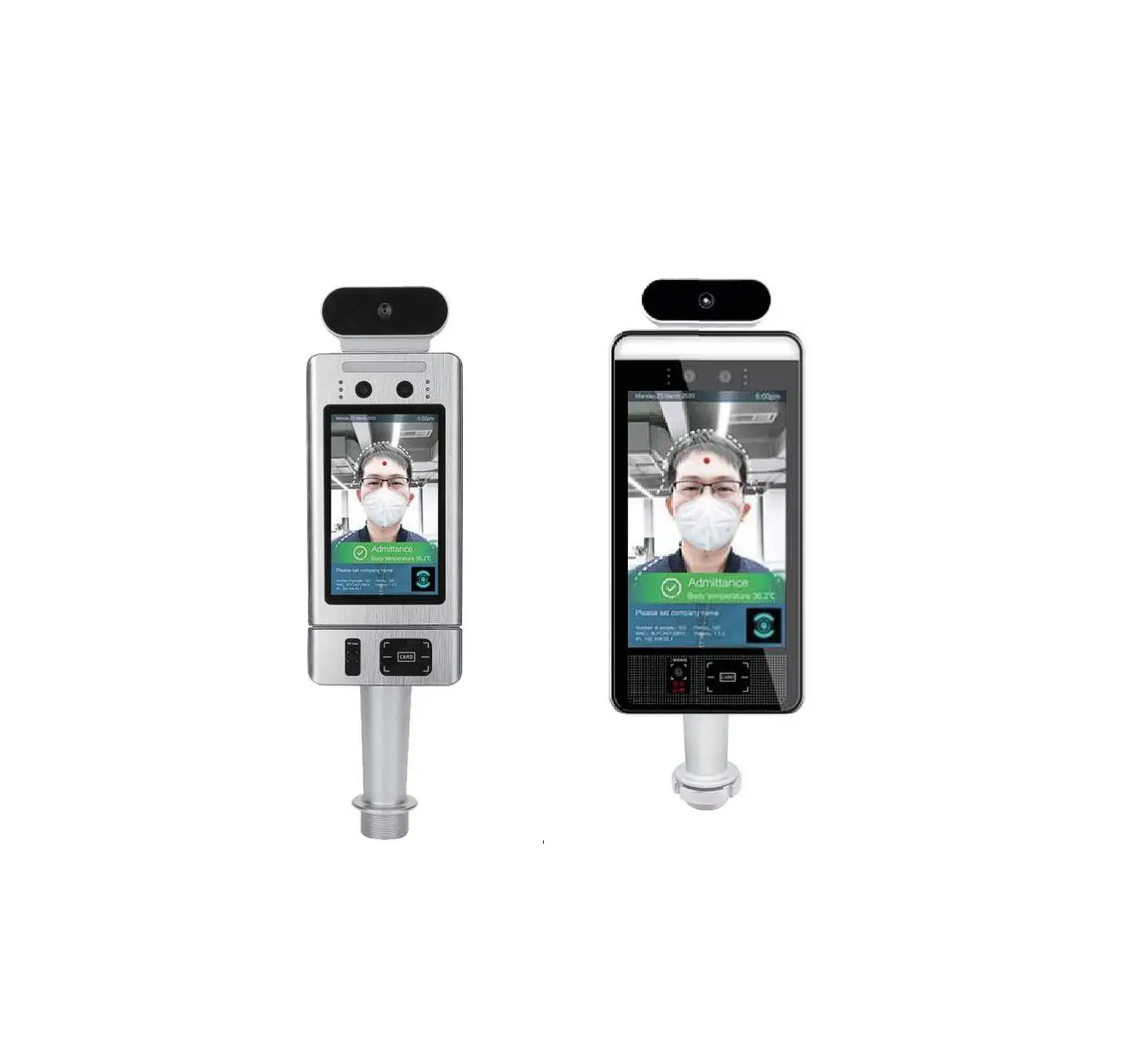
VIPERA JLT-FR1 Pass Management Module of Temperature Measurement & Face
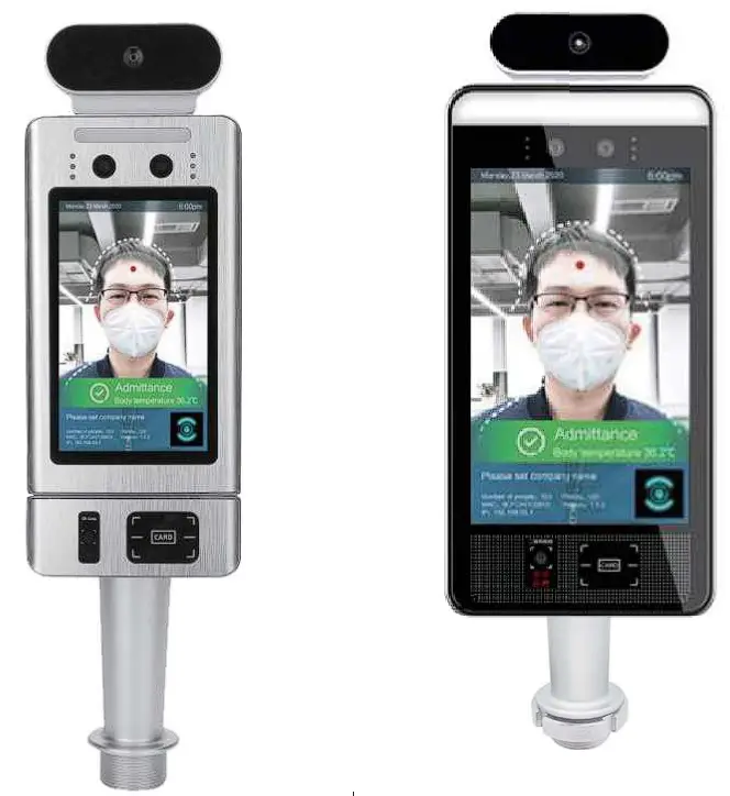
It can be used with access gates and attendance for communities, office buildings, schools, hotels, scenic spots, transportation hubs and other public service places.
Parameters
| Camera | Resolution | 2 million pixels |
| Type | Binocular wide dynamic camera | |
| Aperture | F2.4 | |
| Focusing distance | 50-150cm | |
| White balance | auto | |
| Photo flood light | LED and IR dual photo flood light | |
| Screen | Size | 5.0/8.0 inch IPS LCD screen |
| Resolution | 1280X720/1280*800 | |
| Touch | Not supported (optional support) | |
| Processor | CPU | RK3288 quad-core (optional RK3399 six-core, MSM8953 eight-core) |
| Storage | EMMC 8G | |
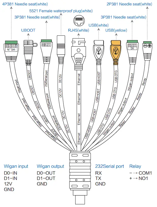
| Interface | Network module | Ethernet and wireless (WI Fl) |
| Audio | 2.5W I 4R speakers | |
| USB | 1 USB OTG, 1 USB HOST standard A port | |
| Serial communication | 1 RS232 serial port | |
| Relay output | 1 door open signal output | |
| Wiegand | One Wiegand 26/34 output, one Wiegand 26/34 input | |
| Upgrade button | Support Uboot upgrade button | |
| Wired network | 1 RJ45 Ethernet socket | |
| Function | Credit card reader | None (optional IC card reader, ID card, ID card) |
| Face Library | Up to 30,000 | |
| 1: N face recognition | Support | |
| 1: 1 face comparison | Support | |
| Stranger detection | Support | |
| Identify distance configuration | Support | |
| UI interface configuration | Support | |
| Upgrade remotely | Support | |
| Interface | Interfaces include device management, personnel / photo management, record query, etc. | |
| Deployment method | Support public cloud deployment, privatized deployment, LAN use, stand-alone use | |
| Temperature detection | Support | |
| Temperature detection distance | 1 meter (optimal distance 0.5 meter) | |
| Infrared thermal imaging module | Temperature measurement accuracy | ≤+ 0.5°C |
| Temperature measurement range | 10°C _42°C | |
| Thermal field of view | 32 X 32°C | |
| Visitors’ temperature is normal and released directly | Support | |
| Abnormal temperature alarm | Support (temperature alarm value can be set) | |
| General parameters | Power | DC12V ( + 10%) |
| Operating temperature | 0°C~60°C | |
| Storage temperature | -20°C~60°C | |
| Power consumption | 13.5W (Max) | |
| Installation method | Gate bracket installation | |
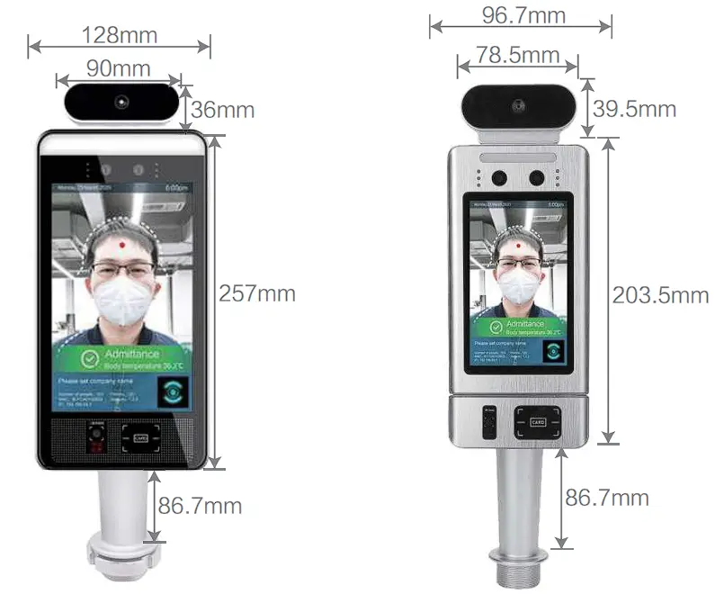
| Size | Standard : 274.24*128*21.48 (mm) | |
| IC card/ ID card: 296.18*132.88*25 (mm) IC card QR code:243*96.7*23.8 (mm) | ||
| Packing list | Machine * 1, power adapter* 1, manual * 1, certificate of conformity* 1 | |
Installation Notes
- Module structure description

- Port description

- Installation method (installed with JL T-FR2)
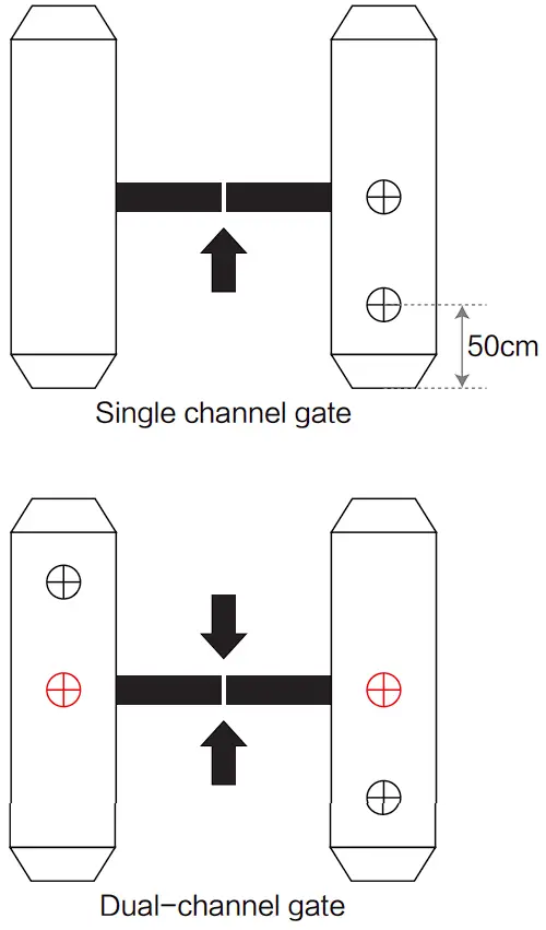
① According to the requirements of the installation site, open a 35mm diameter hole (as shown iri the figure below) in the space position of the gate (usually the middle or front side).
Note: The position of the opening should be based on the actual gate type and scene, and 35mm is for reference only.
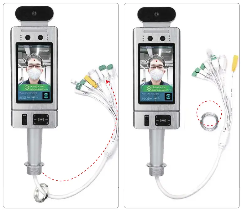
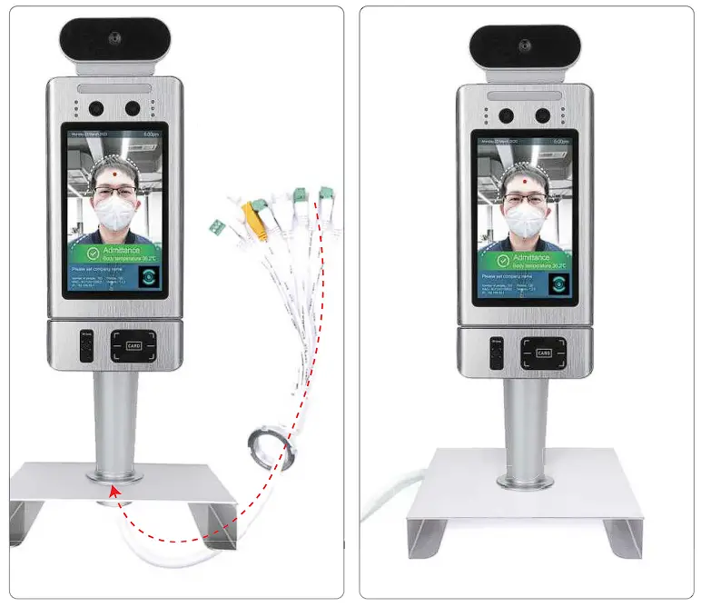
②Unscrew the nut at the bottom of the gate head post, thread the cable out of the nut, and remove the nut.
③Under the gate, insert the cable and cable interface into the gasket and nut in turn, tighten the nut, connect the power supply, and the screen will start.
Care and Maintenance
- During the installation and use of the product, all electrical safetyregulations must be strictly observed.
- Please use the power adapter provided by the regular manufacturer.
For specific requirements of the power adapter, see the product parametertable. - When installing on the gate, please make sure that the product is installed firmly.
- If the product does not work properly, please contact the after-sales service personnel. Do not disassemble or modify the product in any way. (The company does not assume any responsibility for problems caused by unauthorized modification or repair.
- Do not immerse the product in water. When the product is installed outdoors, try to use it with the rain cover provided by our company.
- Please understand that you are responsible for properly configuring all passwords and other related product security settings, and keeping your username and password properly.
- If the equipment does not work properly, please do not disassemble it for repair, otherwise it will affect the equipment warranty.
- Avoid extreme or extreme environments such as extreme high temperature (or low temperature), high humidity, vibration, radiation, and chemical corrosion during installation and use.
Warranty description
- This warranty card is required to be properly kept by the user as a proof of repair.
- This product is guaranteed for one year from the date of purchase.
- Warranty Equipment During the warranty period, under normal use and maintenance conditions, the machine itself malfunctions. Upon inspection, the company will provide free repair and parts replacement.
- During the warranty period, if the following events occur, the company has the right to refuse service or charge materials and maintenance service fees as appropriate.
1) This warranty card and valid proof of purchase cannot be provided.
2) Product failure and damage caused by improper user use.
3) Damage due to abnormal external forces.
4) It is not our maintenance service, and the user dismantles it to cause damage.
5) Failures and damage caused by natural disasters or other force majeure factors.
6) Others intentionally damaged.
5. The company reserves the right to modify and interpret all content.


