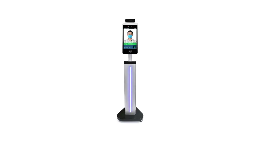
![]() 8-inch ultra-thin Face Temperature Detection Terminal
8-inch ultra-thin Face Temperature Detection Terminal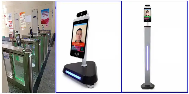
Product Features
- Wide dynamic monocular living anti-counterfeiting, completely solving the deception of various photos on various uploads;
- Support LED intelligent fill light; Support serial port, Wiegand 26-bit, 34-bit output, and support output content configuration; Real-time body temperature monitoring and body temperature tolerance range is accurate to 0.3 °, body temperature detection distance is 0.5-1 meters; Support the device to store thousands of people locally
Environmental Requirements:
Conditions to be avoided during use:
- The sensor should be used in an indoor environment because it is greatly influenced by the environment when used outdoors
- Because of the characteristic of an infrared sensor, the accuracy of measurement will be seriously affected in the application environment, such as the sensor facing the window, air conditioner, radiator, and other high-temperature objects Product Specification Table
| Product model | Category | Performance |
| Camera, Built-in dual-channel ISP | Resolution | 200W |
| Types | RGB + IR |
| Aperture | 4.0mm | |
| Focus | 0 to 2 meters | |
| White balance | Auto | |
| Screen | size | 8-inch. full-view IPS LCD screen |
| Resolution | 1280•800. 400cd 1280 • 800, brightness 400cd | |
| Processor | CPU | RK3288 |
| RAM | DDR3 | 2GB |
| ROM | EMMA | 8GB |
| OS | Android | Android8.1 |
| Accessories | Fill light | Infrared, LED lights |
| Card reader module (Reserved) | card reader, ID card reader and thermal imaging temperature detection module | |
| Network module | Support wired. 2.de wifi | |
| Port | Audio | line out 1 Audio line out |
| USB port | USB2.0 and 2micros | |
| Serial port 232 | 2 R5232 ports, 1 WG input. and with WG output | |
| Wiegand port | 2.Smm, X2PIN | |
| Reset port | Lateral pore position, external |
| buttons | ||
| OTG port | 1 port | |
| General parameters | Protection level | For semi-outdoor or oure outdoor use |
| Power | DC12V | |
| Operating temperature | -10 t-60 t | |
| Working humidity | 10%-90% | |
| Static electricity | 4K/8K | |
| Battery radiation | Not exceeded | |
| Power consumption | 5W MAX | |
| Equipment weight | About3.5 lbs | |
| Equipment size | 373.7•135•85mm |
Dimensions
Standard body temperature
Installation instructions
An Instructions for appearance
The schematic diagram of the gate is shown in the figure below.
Note: If the cable interface is different from the illustration, see the cable supplement on the next page (subject to the actual product and wiring diagram)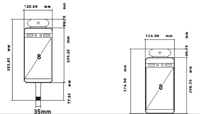
B Instructions for appearance
- According to the requirements of the installation site, a space of 35mm in diameter is generally opened in the middle or front of the gate, as shown in the figure, ⊕ is the recommended opening position.

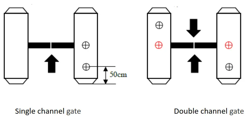
Note: The position of the opening should be based on the actual application and the type of gate 35mm is only a reference.
Unscrew the nut at the bottom of the gate, pass the cable through the nut, and remove the nut, as shown in the figure.
Note: Do not connect the network cable, power cable, etc. At this time to avoid installation trouble 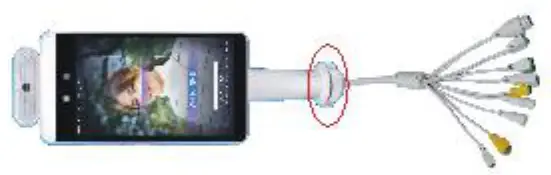 Under the gate, pass the cable and cable interface through the washer and nut in sequence, and tighten the nut to the thread, as shown in the figure.
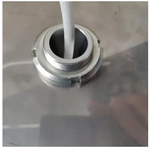
Connect the power and network cable, and the screen will start
Hold the post with both hands and turn it gently to adjust the angle of the gate, as shown in the figure. According to the recognition interface, adjust the gate to the proper recognition angle
For Desktop
The nut needs to be removed, the tail wire is passed through the stainless steel bracket and the nut in sequence, and the angle is tightly tightened; it is suitable for program debugging.
Place the desktop on the desktop, and place the device on the two “L” card positions above the bracket and adjust the angle; It is suitable for the front desk visitors.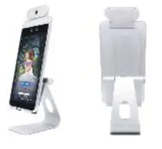
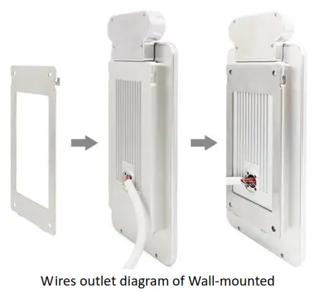
For wall-mounted
- Rotary type: Firstly, put the white 86 switch back box on the wall at 1400mm, and the specific height should depend on the actual use. And then mark the four corners of the back box with a pen, drill four holes with an impact drill, place the rubber plug in the hole, fix the back box with screws, and then do the cable. (This method is installed for surface )If the concealed installation is required, draw a hole in the four sides of the size of the back box with an impact drill. The cement inserted inside should be estimated. After the cement is completely dry, fix the device to the back box with screws, as shown in the figure.

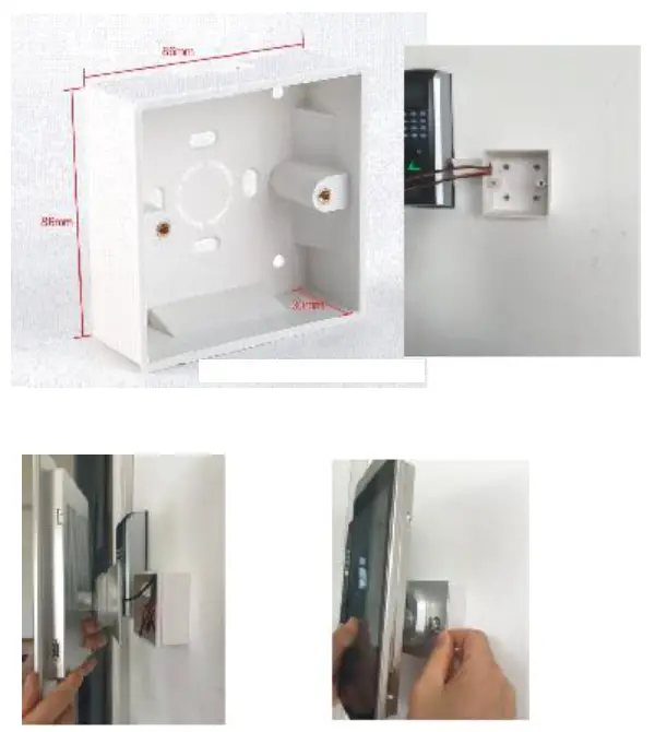
If there is any mistake with hand measure, subject to the actual product.
Note: Before tightening the screws, please ensure that all the tail wires are not crushed by the screws, causing a short circuit.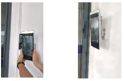 ②Wall-hanging type:
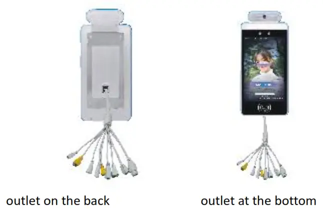
Firstly, remove the stainless steel wall hangings from the device. And then put the stainless steel plate on the wall at an appropriate height, drill four holes with an impact drill, place the rubber plug in the hole, fix the stainless steel plate to the wall with tapping screws.( If the tail wire comes out of the back of the box, it is necessary to make a hole in the wall to facilitate the wiring. If the tail wire comes out from the bottom, it only needs to be fixed and routed with a large white plastic trunking.) As shown in the figure.
 |  |
The cable wiring diagram, as follows
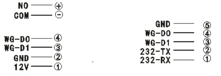
| Switch signal | Wiegand output |
| Wiegand input | signal 232 |
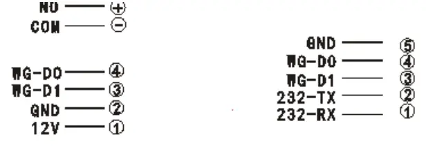
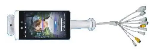
8-inch face recognition tail wire description.
| seven gate tail wires | 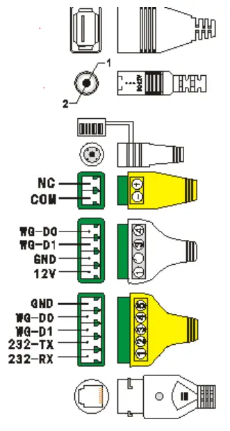 |
| USB2.0 interface | |
| 12V power input | |
| Reset / Reset button | |
| Switch signal | |
| Wiegand input | |
| Wiegand output |
signal 232
RJ45 wired network port
5 Wall-mounted tail wires
| USB2.0 interface | 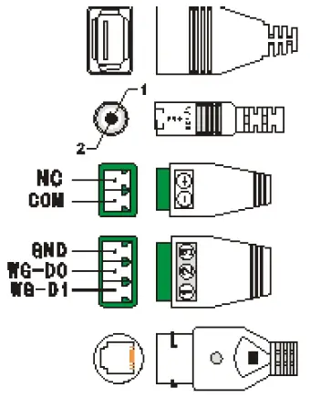 |
| 12V power input | |
| Switch signal | |
| Wiegand output | |
| RJ45 wired network port |
FCC WARNING
This device complies with Part 15 of the FCC Rules. Operation is subject to the following two conditions: (1) this device may not cause harmful interference, and (2) this device must accept any interference received, including interference that may cause undesired operation. Changes or modifications not expressly approved by the party responsible for compliance could void the user’s authority to operate the equipment.
NOTE: This equipment has been tested and found to comply with the limits for a Class B digital device, pursuant to Part 15 of the FCC Rules. These limits are designed to provide reasonable protection against harmful interference in a residential installation. This equipment generates, uses and can radiate radio frequency energy and, if not installed and used in accordance with the instructions, may cause harmful interference to radio communications. However, there is no guarantee that interference will not occur in a particular installation.If this equipment does cause harmful interference to radio or television reception, which can be determined by turning the equipment off and on, the user is encouraged to try to correct the interference by one or more of the following measures:
- Reorient or relocate the receiving antenna.
- Increase the separation between the equipment and receiver.
- Connect the equipment into an outlet on a circuit different from that to which the receiver is connected.
- Consult the dealer or an experienced radio/TV technician for help.
FCC RF warning statement:
RF exposure warning:
This equipment must be installed and operated in accordance with provided instructions and the antenna(s) used for this transmitter must be installed to provide a separation distance of at least 20 cm from all persons and must not be co-located or operating in conjunction with any other antenna or transmitter. End-users and installers must be provided with antenna installation instructions and transmitter operating conditions for satisfying exposure compliance.
Suitable for Brake machine, wall-mounted, desktop, floor-mounted installation Suitable for office areas, hotels, passage gates, office buildings, schools, shopping malls, shops,
communities, construction sites and other public services and management projects that face access control is required.


