![]() TF428/TF228/TF223 Series
TF428/TF228/TF223 Series
BACnet Thermostat Driver
INSTALLATION GUIDE
When Installing This Product
![]() Caution: Must be cut off the power before installation to prevent electric shock.
Caution: Must be cut off the power before installation to prevent electric shock.
- Read this instruction carefully. Failure to follow the instruction might damage the product or cause a hazardous condition.
- Check ratings given in instruction and on the product label to ensure the product is suitable for your applica
- The installer must be a trained, experienced service tech
- After installation is completed, check out product operation as provided in the instruction.
- When the product working. the door of the control cabinet must be closed, or the protection cover installed.
Specifications
| Communication | BACnet MS/TP |
| Power supply | 220/230VAC. 50/60Hz |
| Ambient operating limits | -10°C to 48°C |
| Ambient storage limits | -30°C to 65°C |
| Humidity limits | 5-90% RH, non-condensing |
| Internal power consumption | 6VA |
| Protection class | IP20 |
BACnet Communications
The driver communicates with another module/component through the EIA-485 BACnet protocol.
| Parameter | Definition |
| Cable Type | 18AWG-24AVVG (1-0.5mm) Twist pair, shielded |
| Character impedance | 100-120 ohm |
| Capacitance | <100pF/m |
| Maximum communication distance | 1000m |
| Network topology | Daisy Chain |
| Recommended maximum node number | <40 |
| Baud rate | 9600. 19200. 38400. 76800 (auto-detect ) |
- Termination Resistors
Matched terminating resistors are required at each end of a segmented bus wired across (+) and (-).
Use matched precision resistors rated 1/4W. ±5%. 80 -130 Ohms. Ideally, the value of the terminating resistors should match the rated characteristic impedance of the installed cable. For example, if the installed EIA-485 BACnet cable has a listed characteristic impedance of 120 Ohm, install 120 Ohm matched precision resistors. - Shield Terminating
Following proper EIA-485 BACnet cabling shield grounding procedures is important to minimize the risk of communication problems and equipment damage caused by capacitive coupling.
Capacitive coupling is caused by placing EIA-485 BACnet cabling close to lines carrying higher voltage. The shield should be grounded on only one end of the segment (typically the router end). Tie the shield by using the SHLD on the driver.
Sylk communication
The driver can be connected with one and only one wall module through Syllabus.
The Sylk terminals are connected with two-core wire. The maximum connection length is 60 meters.
LED indications
The driver has one 2-color LED to indicate device state as following:
LED Status | BAC not State Description |
| Green blinking off once in 2.5 sec | The processor is running, but there is no MS/TP token |
| Green blinking off twice in 2.5 sec | The processor is running and there is an MS/TP token |
| Green blinking off thrice in 2.5 sec | The processor is running and there is MS/TP communicalion |
| Solid off | There is no power, my processor is not running. or the pro-cessor is dead |
| Red blinking | Configuration data is an error |
Terminal Definition
No | Symbol | Description |
| RS | Remote Sensor Input (NTC20K) | |
| 2 | COM | Common |
| 3 | PS | Pipe Sensor Input (NTC20K) |
| 4 | RSB1 | Hotel Card (Dry Contact) |
| 5 | COM | Common |
| 6 | RSB2 | Window Contact (Dry Contact) |
| 7 | VM | Valve Modulating Output |
| 8 | COM | Common |
| 9 | Not Used | |
| 10 | Not Used | |
| 11 | Not Used | |
| 12 | S-BUS | Syllabus |
| 13 | S-BUS | Syllabus |
| 14 | BAC+ | BACnet+ |
| 15 | BAC- | BACnet- |
| 16 | SOLD | BACnet Shield |
| 17 | Protective Earthing Wire | |
| 18 | N | Neutral Wire |
| 19 | L | Live Wire |
| 20 | FH | High-Speed Fan |
| 21 | FM | Medium Speed Fan |
| 22 | FL | Low-Speed Fan |
| 23 | vo1 | Heating / Cooling Valve Open |
| 24 | vC1 | Heating / Cooling Valve Close |
| 25 | vo2 | Cooling Valve Open. 4 Pipes Only |
| 26 | vC2 | Cooling Valve Close. 4 Pipes Only |
Terminal Wiring
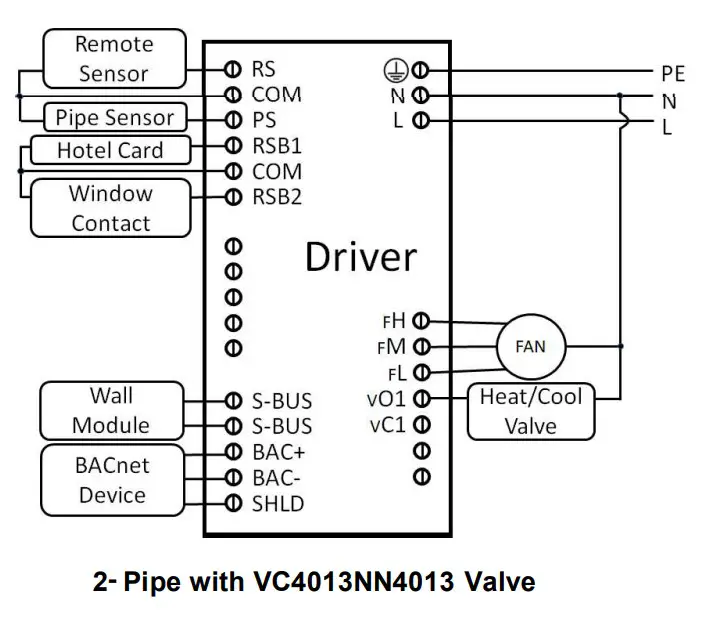 | 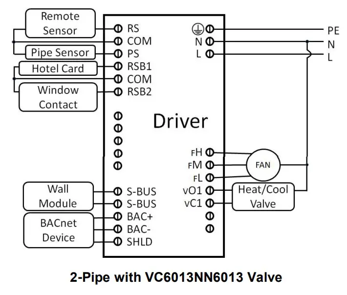 |
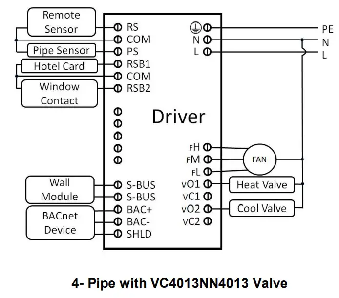 |  |
 | |
Dimensions (mm)
 |  |
Before installation
Review the installation guide and datasheet before installing the driver.
- Make sure the devices are installed and used in physical security places and networks, only the authorized person could operate the devices and access the network.
- Make sure the security of installation and maintenance for the network and upper plant controllers, the detailed information could refer to the plant controllers’ instructions.
- Make sure the devices are all in the isolated internal
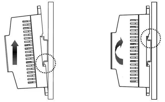
Mounting
The driver enclosure is constructed of a plastic base plate and two DIN rail hooks. The cover does not need to be removed from the base plate for either mounting or wiring.
The driver can be mounted in any orientation. Ventilation openings are designed into the cover to allow proper heat dissipation, regardless of the mounting orientation.![]() The terminal screws must be locked tightly after wiring.
The terminal screws must be locked tightly after wiring.
NOTE: The driver must be mounted in a position that allows clearance for wiring, servicing, and removal.
The driver mounts to DIN rail (standard EN50022; 7.5mm x 35mm).
- Holding the driver with its bottom tilted in towards the DIN rail, hook the two bottom tabs on the back of the driver onto the bottom of the DIN rail.
- Pull up and rotate the driver to make sure the two-tops snap of the driver onto the DIN rail.
Fuse exchange
![]() Must cut off the power before replacing.
Must cut off the power before replacing.
The driver has a built-in fuse, and the cover of the control module should be removed when replacing.
Please wear insulating gloves during the replacement process to prevent damage to the circuit board.
Hazardous Substances and Content in the Product.
Parts | Hazardous substances | |||||
| Pb | Hg | Cd | COI) | PBB | PBDE | |
PCBA | X | 0 | 0 | 0 | 0 | 0 |
| This table is based on SJ/T 11364 | ||||||
| O: the hazardous substances contained in the related part are less than the limit in GB/T 26572 standard. | ||||||
| X: the hazardous substances contained in the related part are more than the limit in GB/T 26572 standard. | ||||||
Other parts all conform to China’s RoHS requirements.
 WEEE Directive 2012/19/EU
At the end of the product, life disposes of the packaging and product in a corresponding recycling center.
Do not dispose of the unit with the usual domestic refuse. Do not burn the product.
![]() www.resideo.com
www.resideo.com
Ademco 1 GmbH Hardhofweg 40
74821 Mosbach
Phone: +49 1801 466 388
[email protected]
homecomfort.resideo.com
@2020 Resideo Technologies, Inc.
All rights reserved.
The Honeywell Home trademark is used under license from Honeywell International Inc.
This product is manufactured by Resideo Technologies, Inc and its affiliates.
![]()
 32332763 001 Rev.A


