Honeywell Home TFxNAP series Sylk Digital Thermostat Installation Guide
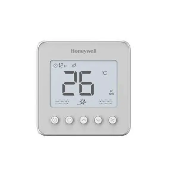
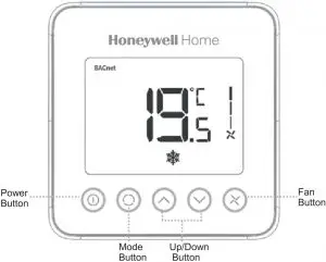
Wall Module Appearance
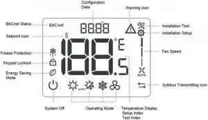
LCD Display
Must be installed by a trained, experienced technician
- Make sure the devices are all used in the isolated internal network, only the authorized person could operate the devices and access to the
- Read this instruction carefully. Failure to follow this instruction can damage the product or cause a hazardous
- Check the product ratings to verify that this product is suitable for your
- The wall module shall work with TF series
- Always test for proper operation after installation.
Installation Tips
Install the wall module about 5 feet(1.5m) above the floor in an area with good airflow at average temperature.
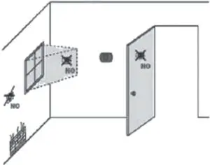
Do not install in location where the wall mod-ule can be affected by:
- Drafts or dead spots behind doors and in corner
- Hot or cold air from ducts
- Sunlight or radiant heat from appliances
- Concealed pipes or chimneys
- Unheated/uncooted area such as an outside wall behind the thermostat
Pre-installation Checklist
Check to make sure your package includes the following items:
- Wall module and terminal wire 1 SET
- Wall module mounting screw 2 PCS
- Wall module wiring connector 2 PCS
- Wall module installation guide (this booklet) 1 PCS
Terminal Designations
Tips: Sylk terminals have no polarity.
| Terminal# | Terminal Name | Description of Function |
| 1 | Sylk | Sylk terminal |
| 2 | Sylk | Sylk terminal |
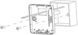
Installation
- Place the wall module back cover over junction box, insert and tighten mounting screws.

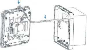
- Insert the terminal wires and connect SYLK communicating wires of the driver with wiring connectors.

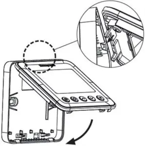
- Align tabs on the back cover with corresponding slots on the back of the wall module, and then push it until the wall module snaps in place.

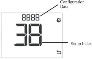
Installer Setup
Press and hold ![]() and
and ![]() buttons 3 seconds to enter setup mode.
buttons 3 seconds to enter setup mode.
- Press
 or
or  button to change the setting
 - Press
 button to switch to next item
 - Press and buttons and hold 3 seconds to exit setup mode and save the settings
- Press
 button to change digital position when setup Device ID.
| ISU Code | Description | Configuration Data |
| 0 | BACnet MAC Address | 0-99, default 1 |
| 1 | System Type | 0 – Heat only |
| 1 – Cool only | ||
| 2 – Two pipe manual (default) | ||
| 3 – Two pipe auto | ||
| 4 – Four pipes manual | ||
| 5 – Four pipes auto | ||
| 2 | Sensor Option | 0 – Onboard Sensor( default) |
| 1 – Remote Sensor | ||
| 3 | Hotel Card (Dry Contact) | 0 – Disabled (default) |
| 1 – Enabled | ||
| 4 | Window Contact (Dry Contact) | 0 – Disabled (default) |
| 1 – Enabled | ||
| 12 | Hotel Card Op- tion | 0 – NO (default) |
| 1 – NC | ||
| 13 | Window Contact Option | 0 – NO (default) |
| 1 – NC | ||
| 20 | Temperature Scale | 0 – °F |
| 1 – °C (default) | ||
| 21 | Fan Control Type | 0 – Cycle only |
| 1 – Constant only low-med-high | ||
| 2 – User can choose Cycle or Constant (default), Low – Med – High – Auto | ||
| 26 | Display Tem- perature adjust- ment | -5°C – 5°C (-10°F -10°F), de- fault 0, step 0.5°C(1°F) |
| 27 | Temperature Display Mode | 0 – display room temperature (Default) |
| 1 – display Setpoint | ||
| 28 | Minimum range stop of setpoint | 10°C – 32°C(50°F-90°F), default 10°C (50°F), step 0.5°C(1°F) |
| 29 | Maximum range stop of setpoint | 10°C – 32°C(50°F-90°F), default 32°C (90°F), step 0.5°C(1°F) |
| 30 | Keypad lockout | 0 – All keys are available (Default) |
| 1 – System button Locked out | ||
| 2 – Fan and System button Locked out | ||
| 3 – All button locked out except power button | ||
| 4 – All buttons are locked | ||
| 32 | ES Heating Setpoint | Range 10-21°C Default : 18 •C (Range 50-70°F Default : 64) |
| 33 | ES Cooling Set- point | Range 22-32°C Default : 26 •C (Range 72-90 °F Default : 79 •F) |
| 35 | Power recovery Status | 0 – OFF |
| 1 – Previous Status (Default) | ||
| 37 | Fan mode in ES mode | 0 – Run at auto fan speed when ISU_21 =2 |
| 1 – Run at low fan speed when ISU_21 = 2 (Default) | ||
| 38 | Device ID | 0-9999, Default 5555 |
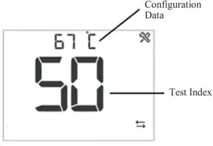
Installer Test
Press ![]() and
and ![]() buttons and hold 3 seconds to enter Installer Test mode.
buttons and hold 3 seconds to enter Installer Test mode.
- Press or button to change the configuration data
- Press button to switch to next index
- Press and buttons and hold 3 seconds to exit test mode
Index | Description | Configuration Data | |
10 | VO (TF228AD/ TF428AD) | 0 – Off | |
1 – On | |||
10 | VM (TF223AD) | 0 – 0V output | |
1 – 2.5V output | |||
2 – 5V output | |||
3 – 7.5V output | |||
4 – 10V output | |||
30 | VO2 (TF428AD) | 0 – Off | |
1 – On | |||
40 | Fan control | 0 – Fan Close | |
1 – Low Speed on | |||
2 – Medium Speed on | |||
3 – High Speed on | |||
50 | Pipe Sensor | Temperature value, If out of range, display “–“. | |
60 | Remote Setback 1 | 0 – Open | |
1 – Close | |||
70 | Remote Setback 2 | 0 – Open | |
1 – Close | |||
80 | Application No. | 0 – TF228AD | |
| 1 – TF428AD | |||
2 – TF223AD | |||
90 | 91 | Software main version | 01 |
92 | Software vice version | 01 | |
| 93 | Configuration Data Main version | 01 | |
Error Code
Error Code | Error Information | Description |
| E1 | Room Temperature error | The room temperature is higher than 48°C or lower than -10°C |
E2 | Sylkbus communica- tion error | Sylkbus communication is failure. |
| E3 | Pipe temperature er- ror | The temperature of pipe sensor is higher than 93° C or lower than 0°C |
E4 | Room temperature and Sylkbus error | Room temperature and Sylkbus communication are both failure. |
| E5 | Room temperature and Pipe temperature error | Room temperature and pipe temperature are both failure. |
E6 | Sylkbus and pipe tem- perature error | Sylkbus communication and pipe temperature are both failure. |
| E7 | Room temperature, pipe temperature and Sylkbus error | Room temperature, pipe temperature and Sylkbus are all failure. |
Hazardous Substances and Content of the Product
Parts | Hazardous substances | |||||
Pb | Hg | Cd | Cr(VI) | PBB | PBDE | |
PCBA | X | O | O | O | O | O |
This table is based on SJ/T 11364. | ||||||
O: the hazardous substances content in the related part are less than the limit in GB/T 26572 standard. | ||||||
X: the hazardous substances content in the related part are more than the limit in GB/T 26572 standard. | ||||||
Other parts all conform to China RoHS requirements.
WEEE Directive 2012/19/EU![]() At the end of the product life dispose of the packaging and product in a corresponding recycling centre. Do not dispose of the unit with the usual domestic refuse. Do not burn the product
At the end of the product life dispose of the packaging and product in a corresponding recycling centre. Do not dispose of the unit with the usual domestic refuse. Do not burn the product


