siaRF MM610X-001 WiFi HaLow Module
Product Information
The Wi-Fi HaLow Module MM610X-001 is a low-power, long-range module based on the IEEE 802.11ah specification. It operates in the spectrum below 1 gigahertz (GHz) and offers longer range and lower power connectivity. The module has excellent RF performance with good sensitivity and selectivity. It comes with a U.FL connector for an external Sub-GHz antenna. The module supports various IO interfaces including UART, SDIO, SPI, I2C, and rich GPIOs for PWM and switch functions. It has been tested to support up to 2000 meters line-of-sight (LOS) distance communication, making it suitable for both indoor and outdoor IoT applications. The module has a throughput of 20Mbps UDP and a Phy data rate of 32.5Mbps.
Product Usage Instructions
- Connect the Wi-Fi HaLow Module MM610X-001 to your device using the appropriate IO interface (UART, SDIO, SPI, or I2C) and ensure a proper power supply within the range of 3.0V to 3.6V.
- If you plan to use an external antenna, connect it to the module using the U.FL connector.
- Ensure that your device is within the supported frequency range of 850-950 MHz.
- Configure the module according to your requirements using the available GPIOs for PWM and switch functions.
- To establish communication, make sure that there is a clear line-of-sight (LOS) distance of up to 2000 meters between the module and the target device.
- For security purposes, you can utilize the AES encryption engine and hardware support for SHA1 and SHA2 hash functions. Additionally, the module supports WPA3 encryption, including protected management frames (PMF) and Opportunistic Wireless Encryption (OWE).
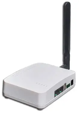
- If you intend to bridge Wi-Fi to Wi-Fi HaLow networks, use the module as a Wi-Fi HaLow Bridge. It can also be used as a Wi-Fi HaLow Client Adapter/Dongle or for Smart City Networks.
- Ensure that the module is operated within the specified temperature range of -40 to 70 degrees Celsius.
Please refer to the user manual for detailed instructions on configuring and integrating the Wi-Fi HaLow Module MM610X-001 into your specific device or application.
Product overview
- MM610X-001 is a Wi-Fi HaLow Sub-GHz wireless module based on Morse Micro® MM6108 RF SOC.
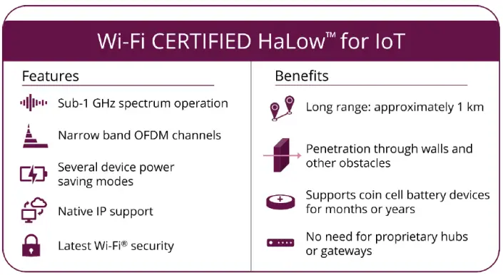
- HaLow (pronounced halo) is a low-power, long-range version of the IEEE 802.11Wi-Fi standard. HaLow is based on the Wi-Fi Alliance 802.11ah specification and is expected to play an important part in the Internet of Things (IoT).
- Wi-Fi CERTIFIED HaLow™, the designation for products incorporating IEEE 802.11ah technology, augments Wi-Fi by operating in spectrum below 1 gigahertz (GHz) to offer longer range and lower power connectivity.
- Excellent RF performance, MM610X-001 module has excellent sensitivity with good selectivity and blocking performance. MM610X-001 module come with U.FL connector for external Sub-GHz antenna.
- There are many IO interfaces: UART, SDIO, SPI, I2C and rich GPIOs for PWM and switch functions.
- 2 KMs LOS distance communication: MM610X-001 module is tested to support up to 2000 meters LOS distance communication, good for both indoor and outdoor IoT applications.
- 20Mbps UDP Throughput is the best capacity compared with all Wireless IoT long distance throughput. The Phy data rate is 32.5Mbps.
Wi-Fi CERTIFIED HaLow™ for loT
Features
Protocol
- 802.11ah OFDM PHY supporting future WFA HaLow certification
- BPSK & QPSK, 16-QAM & 64-QAM Modulation
- Automatic frequency & gain control
- Packet detect & channel equalization
- Forward Error Correction (FEC) coding & decoding
- Supports Modulation and Coding Scheme (MCS) levels MCS 0-7 and MCS 10
- Supports 1 MHz and 2MHz duplicate mode
- Supports optional Traveling Pilot
- 802.11ah MAC supporting WFA HaLow certification
- Support for STA and AP roles
- Listen-Before-Talk (LBT) access with energy detect
- 802.11 power save
- 802.11 fragmentation and defragmentation
- Power-Saving Target Wake Time (TWT) support for long battery life
- Automatic and manual MCS rate selection
Radio Operation
- Single-stream max data rate of 32.5 Mbps (MCS=7, 64-QAM, 8MHz channel, 4 μSec GI)
- Radio supporting worldwide Sub-1 GHz frequency bands
- Frequency Range: 850-950 MHz
- Channel width options of 1/2/4/8 MHz
Transmitter Performance
- Tx output power (dBm): +21 dBm (Typical) MCS0
RF Interface
- External antenna connector
Power Management Unit (PMU) for various modes of operation
- Power-down (interrupt driven wake)
- Hibernate mode (internal / external wake)
- Target Wake Time mode
- Active Receive / Transmit mode
- Integrated DC-DC converter supports a wide supply voltage, from 3.0V to 3.6V
Regulatory Certifications coming soon
- CE/FCC/IC/TELEC/NCC/RCM
- ESD: HBM 2KV / MM 200V, Latch-up: 150mA
- Halogen-free / RoHS 2.0 / Reach Annex 14 & 17
Operating Range
- 3.0-3.6V for VBATT and VDDFEM. 1.8-3.6V for VDDIO
- -40 to +70°C
Dimensions
- 22 mm x 17.0 mm x 2.0 mm (module)
Security
- AES encryption engine
- Hardware support for SHA1 and SHA2 hash functions (SHA-256, SHA-384, SHA-512)
- WPA3 including protected management frames (PMF)
- Opportunistic Wireless Encryption (OWE)
MCU Peripherals
- 12-bit 1 Msps SAR ADC
- 12 × GPIO
- 2 × UART, 1 x SPI, 1 x I2C
- Power Management Unit for power state switching
- SDIO 2.0 compliant slave interface
- SDIO 2.0 Default Speed (DS) at 25MHz
- SDIO 2.0 High Speed (HS) at 50MHz
- Support for both 1-bit and 4-bit data mode
- Support for SPI mode operation
Surveillance Cameras and Sensors
- Cloud Connectivity
- Low-power Sensor Networks
- Building Automation Systems (BAS)
- Asset Tracking and Management
- Machine Performance Monitors & Sensors
- Building Access Control & Security
- Drone Video and Navigation Communications
- Connected Toys and Games
- Rural Internet Access
- Agricultural and Farm Networks
- Utility Smart Meter and Intelligent Grid
- Proximity Sensors
- Industrial Automation Controls
- Smart Home Automation
- EV Car Chargers
- Appliances
- Construction Site Connectivity
- Smart Signs and Kiosks
- Retail Point-of-Sale Terminals
- Vehicle-to-Vehicle Communications
- IP Sensor Networks
- Biometric IDs and Keypads
- Warehouse Connectivity
- Intelligent Lighting Controls
- BT/ZigBee(™)/Z-Wave(™) to Wi-Fi HaLow Gateways
- Wi-Fi to Wi-Fi HaLow Bridges
- Wi-Fi HaLow Client Adapters/Dongles
- Smart City Networks
Specification
| Item | Specification |
| RF Transmit Power | Tx output power (dBm): +21 dBm (Typical)@MCS0 (+/- 2dBm) +18 dBm (Typical)@MCS7 (+/- 2dBm) |
| Antenna | 1 x UFL (IPEX) connector |
| PHY Rate | Up to 32.5Mbps |
| Physical Connectors | 43 holes PCB board edge stamp holes |
| Operation Voltage | 3.0V to 3.6V |
| Operation Temperature | -40 to 70 ℃ |
| Security | WPA3 |
| Host Interface | SDIO, SPI |
RF Receiver Sensitivity
| MCS Index | Modulatio n Scheme | Coding Rate | Phy Rate (kbps) per BW | Spec Sensitivity (dBm) per BW | ||||||
| 1MHz | 2Mhz | 4MHz | 8MHz | 1MHz | 2Mhz | 4MHz | 8MHz | |||
| 0 | BPSK | 1/2 | 333 | 722 | 1500 | 3250 | –105 | -103 | –101 | –97 |
| 1 | QPSK | 1/2 | 667 | 1444 | 3000 | 6500 | –102 | -100 | –97 | –93 |
| 2 | QPSK | 3/4 | 1000 | 2167 | 4500 | 9750 | –99 | -97 | –95 | –92 |
| 3 | 16-QAM | 1/2 | 1333 | 2889 | 6000 | 13000 | –96 | -94 | –91 | –88 |
| 4 | 16-QAM | 3/4 | 2000 | 4333 | 9000 | 19500 | –93 | -90 | –88 | –85 |
| 5 | 64-QAM | 2/3 | 2667 | 5778 | 12000 | 26000 | –89 | -87 | –84 | –81 |
| 6 | 64-QAM | 3/4 | 3000 | 6500 | 13500 | 29250 | –88 | -85 | –83 | –80 |
| 7 | 64-QAM | 5/6 | 3333 | 7222 | 15000 | 325500 | –87 | -84 | –81 | –78 |
| 10 | BPSK | 1/2 x 2 | 167 | N/A | –107 | N/A | ||||
Transmit Power consumption
| Mode | Condition TA=25℃, VBAT=VDDIO=3.3V | VBAT Current (Typ) | VFEM (Typ) | Unit |
| Transmit Current (MCS7, 16dBm, 100% D.C.) | 1MHz channel | 51 | 104 | mA |
| 2MHz channel | 55 | 104 | mA | |
| 4MHz channel | 62 | 102 | mA | |
| 8MHz channel | 72 | 99 | mA | |
| Transmit Current (MCS0, 21dBm, 100% D.C.) | 1MHz channel | 57 | 151 | mA |
| 2MHz channel | 60 | 151 | mA | |
| 4MHz channel | 66 | 151 | mA | |
| 8MHz channel | 78 | 147 | mA |
FCC Compliance Statement:
This device complies with Part 15 of the FCC Rules. Operation is subject to the following two conditions:
- This device may not cause harmful interference, and
- this device must accept any interference received, including interference that may cause undesired operation.
This device must accept any interference received, including interference that may cause undesired operation. Product that is a radio transmitter is labeled with FCC ID.
FCC Caution
- Exposure to Radio Frequency Radiation. This equipment must be installed and operated in accordance with provided instructions and the antenna(s) used for this transmitter must be installed to provide a separation distance of at least 20 cm from all persons and must not be collocated or operating in conjunction with any other antenna or transmitter. End-users and installers must be provided with antenna installation instructions and transmitter operating conditions for satisfying RF exposure compliance.
- Any changes or modifications not expressly approved by the grantee of this device could void the user’s authority to operate the equipment.
- This Transmitter must not be co-located or operating in conjunction with any other antenna or transmitter.
- Changes or modifications to this unit not expressly approved by the party responsible for compliance could void the user authority to operate the equipment.
IMPORTANT NOTE: In the event that these conditions cannot be met (for example certain laptop configurations or colocation with another transmitter), then the FCC authorization is no longer considered valid, and the FCC ID cannot be used on the final product. In these circumstances, the OEM integrator will be responsible for re-evaluating the end product (including the transmitter) and obtaining a separate FCC authorization.
The modular transmitter is only FCC authorized for the specific rule partslisted on the grant, and that the product manufacturer is responsible for compliance to any other FCC rules that apply to the host not covered by the modular transmitter grant of certification.
The module has been tested for compliance to FCC Part 15 (15.247)
If the grantee markets their product as being Part 15 Subpart B compliant (when it also contains unintentional-radiator digital circuity), then the grantee shall provide a notice stating that the final host product still requires Part 15 Subpart B compliance testing with the modular transmitter installed.
OEM integration instructions:
This device is intended only for OEM integrators under the following conditions,
The module is only limited to installation in mobile applications. The antenna must be
installed such that 20 cm is
maintained between the antenna and users, and the transmitter module may not be
co-located with any other transmit or antenna. The module shall be only used with the
integral antenna(s) that has been originally tested and certified with this module.
As long as 3 conditions above are met, further transmitter test will not be required.
However, the OEM integrator is still responsible for testing their end-product for any
additional compliance requirement with this module installed (for example, digital device
emission, PC peripheral requirements, etc.)
OEM integration instructions:
In the event that these conditions cannot be met (for example certain laptop configuration
or co-location with another transmitter), then the FCC authorization for this module in
combination with the host equipment is no longer considered valid and the FCC ID of the
module cannot be used on the final product. In these and circumstance, the OEM integrator
will be responsible for re-evaluating. The end product (including the transmitter) and
obtaining a separate FCC authorization
End product labeling:
This transmitter module is authorization only for use in device where the antenna may be
installed such that 20 cm may be maintained between the antenna and users. The final end
product must be labeled in a visible area with the following,
“Contains Transmitter Module FCC ID: TKZMM610X-001 or Contains FCC ID:
TKZMM610X-001”
The end product shall bear the following 15.19 statement: This device complies with part 15 of the FCC Rules. Operation is subject to the following two conditions: (1) This device may not cause harmful interference, and (2) this device must accept any interference received, including interference that may cause undesired operation.
Information that must be placed in the end user manual:
The OEM integrator has to be aware not to provide information to the end user regarding
how to install or remove this RF module in the user’s manual of the end product which
integrates this module. The end user manual shall include all required regulatory
information/warning as show in this manual.


