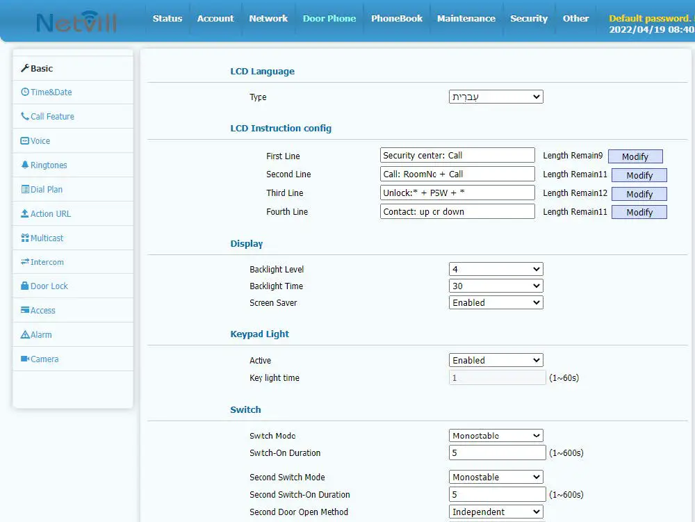
Netvill DP88A SIP Door Phone
Packing List
| DP88A Device | Installation diagram | Accessories | RFID Card |
|  |  |  |
Material Specification
DP88A Device Dimension 285*120*38mm
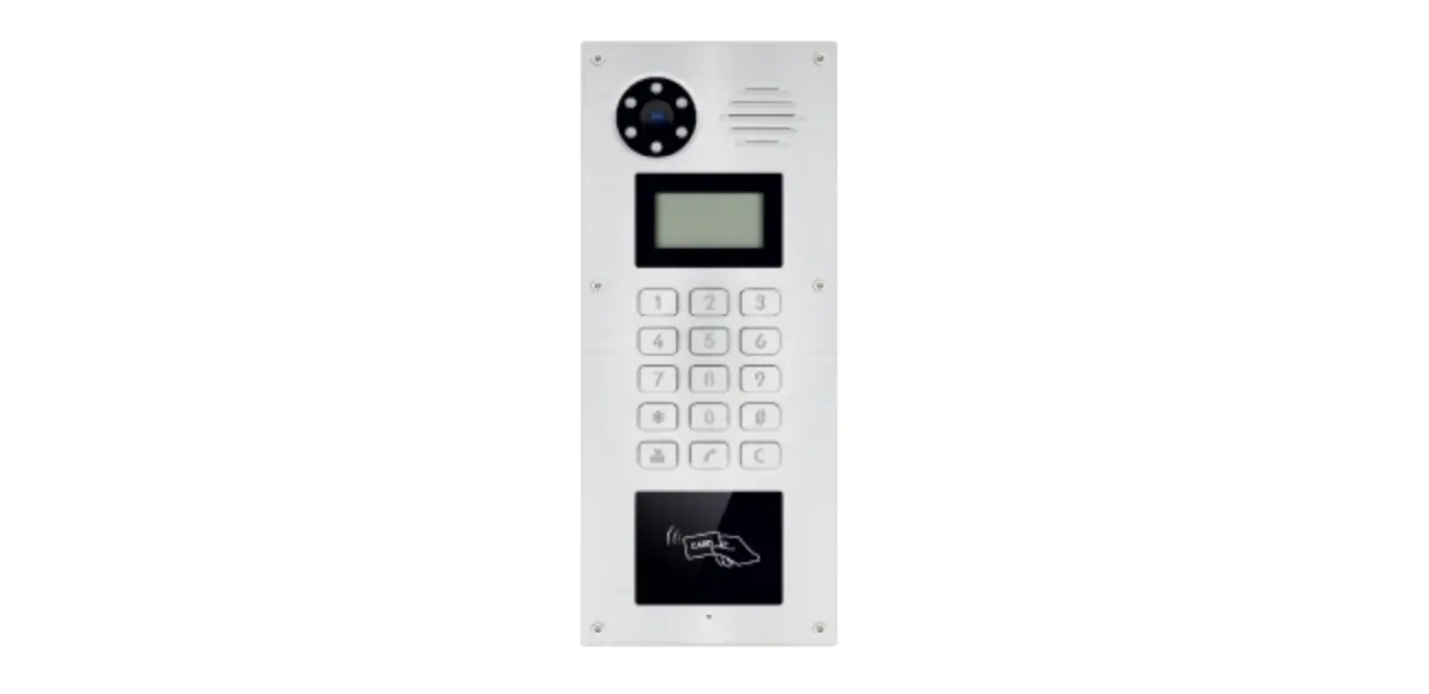
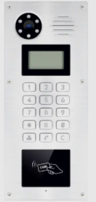
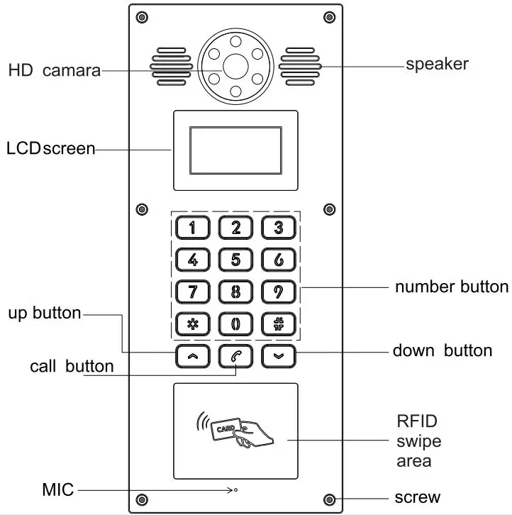
Front Panel
Wiring Port Specification
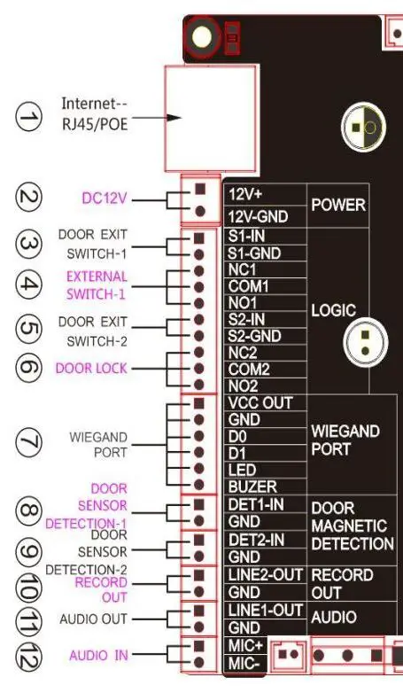
(Picture III)
| Item | Description |
| 1 | Internet Port: Standard RJ45 port,10/100M Adaptive, suggest use CAT5 or CAT5E line. |
| 2 | Power Adaptor:12V/1A input, left port is “+”,right port is “-” |
| 3,5 | Door Exit Switch: To connect indoor exit button |
| 4,6 | External Switch/Door Lock: To connect door lock, alarm etc. |
| 7 | Wiegand Port: To connect Wiegand card reader. |
| 8,9 | Door sensor detection: to detect the door open/close status. |
| 10 | To mix device voice & remote call voice, then release them together. 1 port is for record, another port is for GND. |
| 12 | Audio Input: To connect a external audio signal. |
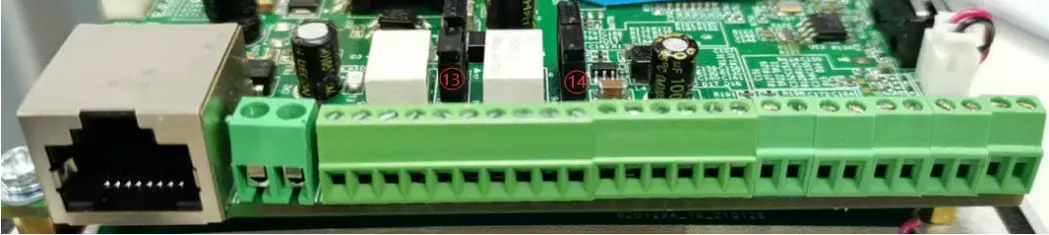
| 13 | JP1 jumper(Picture II) |
| 14 | JP6 jumper (Picture II) |
JP1, JP6 Jumper
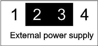
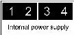
Door lock control include 2 models (default is internal power supply), see as below,
Internal power supply: If electric lock starting current less than 500mA/12V, can use internal drive model, electric lock port is 12V DC output.
(Picture IV) 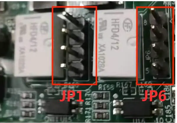
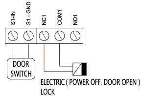
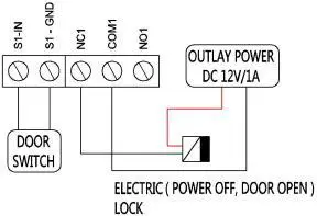
Wiring Description
- NO: Normal Open, working status electric lock is open;
- COM: Common port;

Normal Closed, working status electric lock is closed;
| Power Supply Type | Electric Lock type | JP1 Jumper | Wiring Diagram | ||
| Internal | External | Power off, door open | Power on, door open | ||
| √ | √ |  |  | ||
| √ | √ |
| | ||
| √ | √ |
|  | ||
| √ | √ |
| | ||
| Power Supply Type | Electric Lock type | JP6 Jumper | Wiring Diagram | ||
| Internal | External | Power off, door open | Power on, door open | ||
| √ | √ |
| | ||
| √ | √ |
| | ||
| √ | √ |
| | ||
| √ | √ |
| | ||
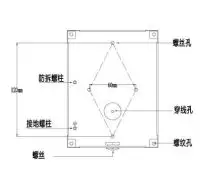
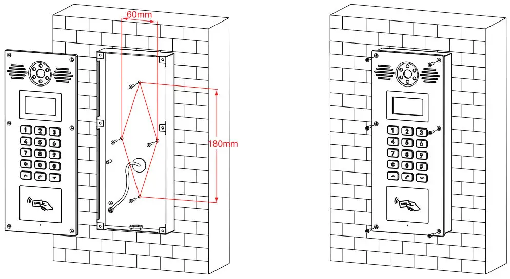
Installation
- Drill 4 holes on the wall, space is 60*120mm(DP88 space is 60*180mm), insert Plastic expansion tube, use KA4*30 screws to fix back panel on the wall. (see Picture V)
- Use 4 pcs M3*8 screws from the front panel to fix back panel(DP88 use 6 pcs screws).(Picture VI)
Get the device IP address
After device connect to the power supply, default way to get IP address is DHCP. Press “963 + call button”, the device voice will read IP address, then also device LCD will display IP address.
Door Access Configuration
Log in the Device Web GUI
To input the device IP on the web browser. (for example: input http://172.28.4.131 ), and then entry the log in interface, default account: admin, default password: admin ) 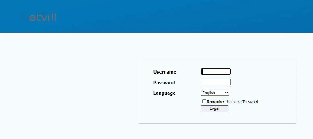
Configure SIP Account
To configure SIP account, Active, register name, username password , SIP server address & port, then submit. 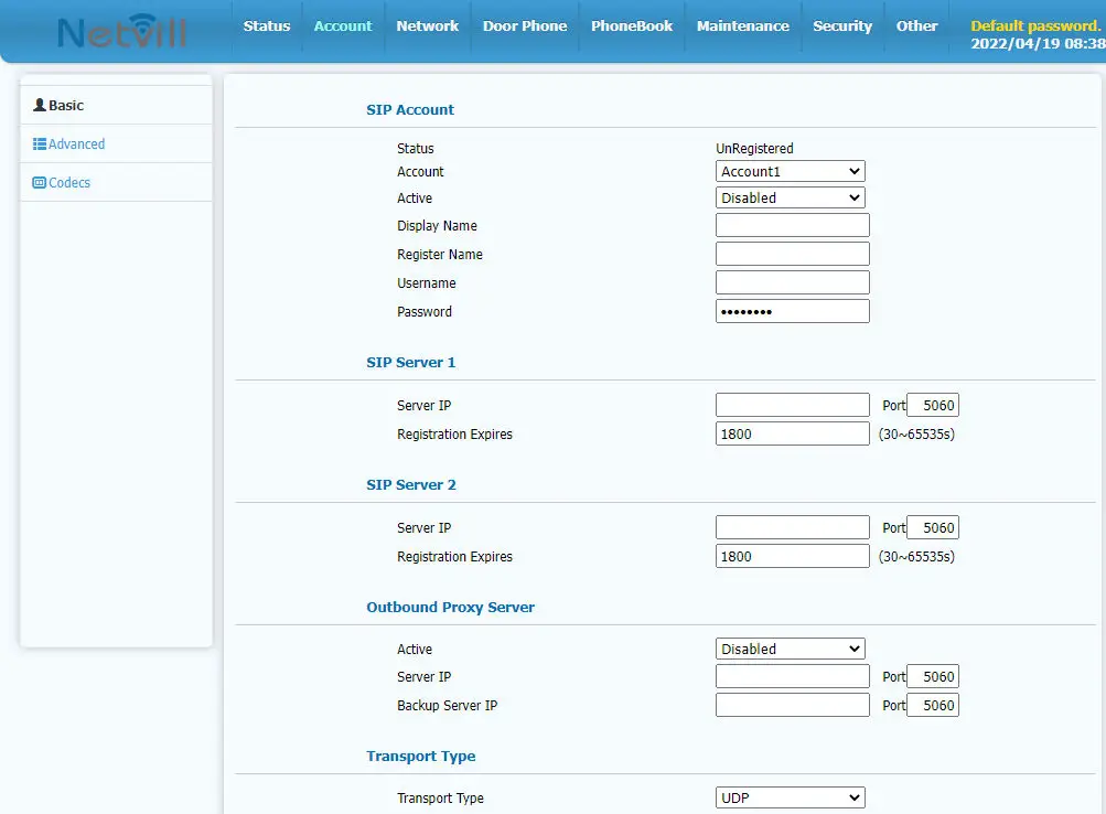
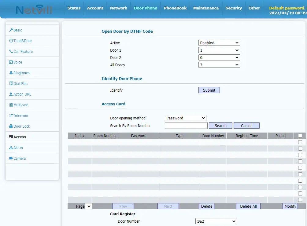
To configure Door Access Parameter
- In “Access- Open Door by DTMF Code” to configure DTMF code of indoor station.
- In “Access- Access Card” to add RFID card & password.
- In “Access- Open Door By HTTP” to configure username & password of HTTP door open.
Door Open Configuration
In “Door Phone- Basic” to configure Switch Model, and Card Reader Model.