
HELLA GUTMANN MT-HV Solutions
About these Operating Instructions
The operating instructions comprise the most important information in a clearly visible form to facilitate the start with the MT-HV.
Notes about the Use of these Operating Instructions
These operating instructions contain important information relevant to operator safety.
Go to www.hella-gutmann.com/manuals to find all the manuals, instructions, references and lists about our diagnostic devices, tools and much more.
Please also visit our Hella Academy under www.hella-academy.com and expand your knowledge with various online tutorials and other training courses.
Please read the operating instructions entirely. Pay special attention to the first pages containing the safety instructions. They are provided solely to assure your safety when working with the product.
When working with the product, it is recommended to read the individual work steps in the manual again to prevent hazard of persons and equipment or operating errors.
The product shall be used exclusively by a qualified person. Information and knowledge included in this training is not explained in these operating instructions.
The manufacturer reserves the right to modify these instructions and the product itself without prior notice. We therefore recommend checking it for any updates. These operating instructions must accompany the product in case of sale or any other transfer.
These operating instructions shall be kept for the entire service life of the product and shall be accessible at any time.
Symbols Used
Marking of Text Parts
| DANGER Text parts marked in this way indicate an imminent dangerous situation, which will lead to death or severe injuries if not avoided. |
| WARNING Text parts marked in this way indicate a possibly dangerous situation, which may lead to death or severe injuries if not avoided. |
| WARNING Text parts marked in this way indicate a possibly dangerous situation, which may lead to death or severe injuries if not avoided. |
| This symbol indicates dangerous electric voltage/high voltage. |
| |
These symbols indicate rotating parts. |
| This symbol indicates the risk of crushing limbs. |
| This symbol indicates a potential injury of the hand. |
| This symbol indicates a potential chemical burn. |
| NOTICE All texts labeled IMPORTANT refer to a hazard in the device or environment. The advices or rather instructions stated here must therefore be observed by all means. |
| NOTICE Texts marked with NOTICE contain important and helpful information. It is recommended to observe these texts. |
| Crossed out waste bin This symbol indicates that the product must not be discarded as domestic waste. The bar underneath the waste bin symbol indicates that the product has been put on the market after 13 August 2005. |
| Refer to manual This marking indicates that the user manual must always be read and always be available. |
Symbols on the Product
Symbols on the Product
DANGER
Text parts marked in this way indicate an imminent dangerous situation, which will lead to death or severe injuries if not avoided.
WARNING
Text parts marked in this way indicate a possibly dangerous situation, which may lead to death or severe injuries if not avoided.
CAUTION
Text parts marked in this way indicate a possibly dangerous situation, which may lead to minor or slight injuries if not avoided.
Refer to manual
This marking indicates that the user manual/the operating instructions must always be read and
always be available.
Direct current voltage
This symbol indicates direct current voltage.
Direct current voltage means that the electrical voltage does not change throughout a longer period of time.
Polarity
This symbol indicates a plus connection of a voltage source.
Ground connection
This symbol indicates a ground connection of a voltage source.
User Information
Safety precautions
General Safety Precautions
|
| All notes apply which are given in the individual sections of
the MT-HV operating instructions and in the user documentation of the mega macs X. All the symbols on the MT-HV and the following measures and safety precautions shall also be observed.
|
Safety Precautions for the MT-HV
|
| Observe the following to avoid incorrect handling and injury to the user or destruction of the MT- HV arising from this:
|
Safety Precautions for High Voltage/Line Voltage
|
| It is a precondition for performing high-voltage measurements that the user has knowledge of automotive technology and is therefore aware of the sources of danger and risks in the workshop and on motor vehicles. An additional country-specific qualification is mandatory. Very high voltages occur in electrical systems. Due to voltage flashover on damaged components, such as marten damage or touching live components, the risk of electric shock is likely. Voltage flashover can occur e.g. on the primary and secondary side of the ignition system, the connection to the vehicle, the lighting systems or the wiring harness with plug connections. Therefore regard the following:
• Do not touch live components when the ignition is on. |
Safety Precautions – Chemical Burns
|
| In case of improper use electrolyte may escape from the battery and may cause chemical burn of eyes, respiratory system and skin. Therefore regard the following:
|
Safety Precautions – Risk of Injury
|
| When working on the vehicle, there is a risk of injury through rotating parts or rolling of the vehicle. Therefore regard the following:
|
Safety Precautions for Hybrid/Electric Vehicles
|
| Any work on high-voltage systems is allowed only when wearing the corresponding personal protective equipment. Very high tensions occur on hybrid and electric vehicles. Due to voltage flashover on damaged components, such as marten damage or touching live components, the risk of electric shock is likely. High voltage at or in the vehicle can lead to death in case of inattention. Therefore regard the following:
Skilled electrician for predetermined operations – Hybrid or rather electric vehicles
g. with insulating cloth, hoses or plastic coverings. Voltage higher than 1000 V: Cover the parts with insulating plates/protective panels specially developed for this purpose so that sufficient protection against contact to adjacent parts is ensured.
|
Non-Liability
Burden of Proof on the User
The burden of proof is on the user of the product, that he has paid attention to technical explanations, notes on operation, equipment care as well as maintenance and safety without exception.
Documentation
The information given describes the most common fault causes. However, there are often further causes of existing faults which cannot be listed here, or there are further sources of error which as yet are unknown. The Hella Gutmann Solutions GmbH does not accept any liability for failed, unnecessary or incorrectly performed repair work.
Hella Gutmann Solutions GmbH does not accept any liability for the use of data and information that is found to be incorrect or that was incorrectly displayed, or for errors that occurred inadvertently during the compilation of the data.
The Hella Gutmann Solutions GmbH will not take any liability arising from the errors and misuse mentioned before and further losses of profit or company value thereof.
The Hella Gutmann Solutions GmbH does not accept any liability for damages or operational disruptions resulting from failure to observe the operating instructions and the special safety precautions.
The burden of proof is on the user of the product, that he has paid attention to technical explanations, notes on operation, equipment care as well as maintenance and safety without exception.
Device Description
Delivery contents
Basic
| Pieces | Name | |
|
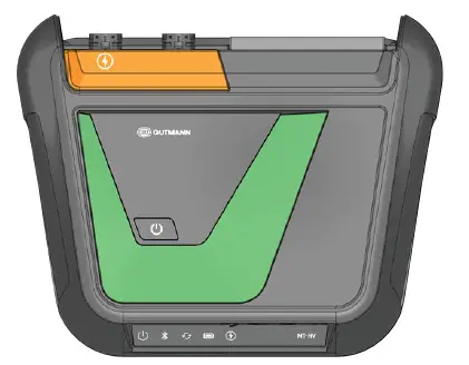
1 |
MT-HV |   |
|
1 |
Power adapter and power cord | 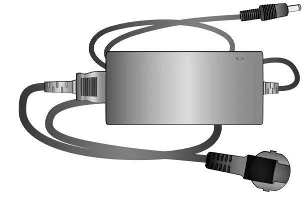 |
| 1 | USB cable (type C – type C) | 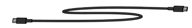 |
| 1 | Operating instructions | 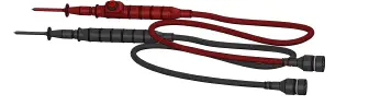 |
Positive
| Pieces | Name | |
|
1 |
MT-HV | |
|
1 |
Power adapter and power cord | |
| 1 | USB cable (type C – type C) | |
| 1 | High-voltage test leads black/red | |
| 1 | Operating instructions | |
Pro
| Pieces | Name | |
|
1 |
MT-HV | |
|
1 |
Power adapter and power cord | |
| 1 | USB cable (type C – type C) | |
| 1 | High-voltage test leads black/red | |
|
1 |
MT 77 | 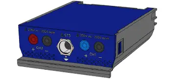 |
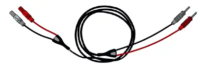
| 1 | Black/blue test lead | |
| 1 | Red/black test lead |
|
| 1 | Operating instructions | |
Checking Delivery Contents
Please check the delivery contents upon receiving your device so that complaints can be issued immediately regarding any potential damage.
Proceed as follows to check the delivery contents:
- Open the package supplied and check for completeness based on the delivery slip.
Should you identify any damage to the package, then open the package in the presence of the delivery service and check the MT-HV for hidden damage. Any transport damage to the package supplied and damage to the MT-HV shall be registered in a damage report by the delivery service. - . Take the MT-HV out of the packaging.
CAUTION
Danger of short circuit due to loose parts in or at the MT-HV
Danger of destruction of the MT-HV and/or the automotive electronics
Never put the MT-HV into operation if you suspect that there are loose parts in or at the module. In this case please contact the Hella Gutmann repair service or a Hella Gutmann trading partner immediately. - Check the MT-HV for mechanical damage and shake slightly to ensure that there are no loose parts inside.
Intended Use
The MT-HV is a mobile measurement module with which you can measure voltage, current, resistance and pressure.
You can use the MT-HV both for measuring high voltages and low voltages. Use the installed high-voltage measurement module for high-voltage measurements. You can insert another measurement module into the MT-HV for low-voltage measurements.
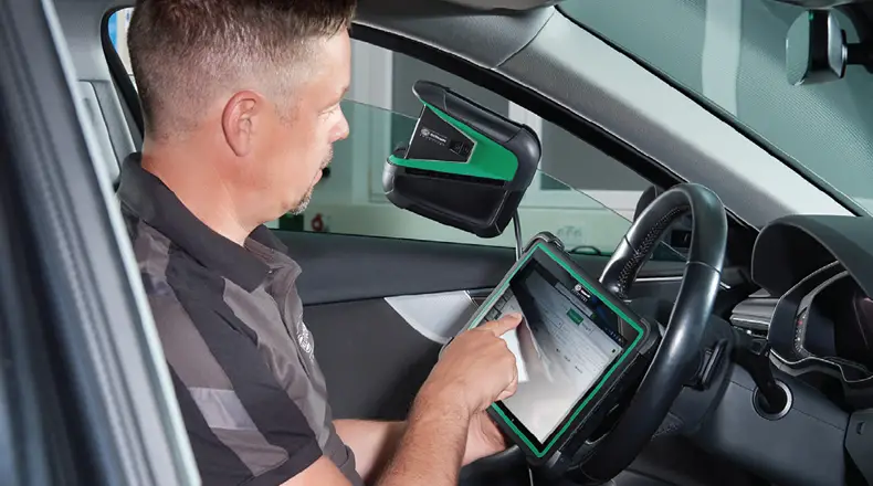
The MT-HV can be operated only in connection with the mega macs X of Hella Gutmann. The communication between the mega macs X and the MT-HV is realized via Bluetooth®. Diagnostic devices from other manufacturers will not be supported. The MT-HV is not suitable for the following repair work/voltage measurements:
- Electric appliances and devices
- Home electrics
- Power supply systems/line voltage
If the MT-HV is used in a way not authorized by Hella Gutmann, the protection of the MT-HV and the mega macs X may be influenced.
Using the Bluetooth® Function
NOTICE
Alternatively, you can also operate the MT-HV with USB cable connected to the mega macs X.
The terms of use of the Bluetooth® function may be restricted or prohibited through law or corresponding legal regulations in certain countries.
Pay attention to the provisions in force in the respective country before using the Bluetooth® function.
MT-HV
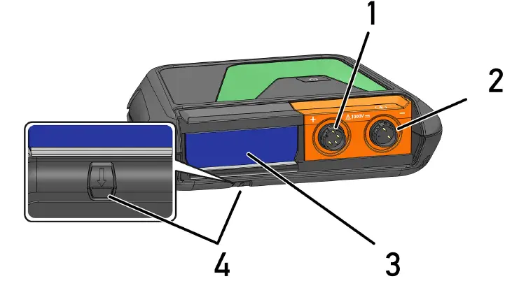
| Name | |
| 1 | Connection of HV test lead Connect the red high-voltage test lead here. |
| 2 | Connection of HV test lead Connect the black high-voltage test lead here. |
| 3 | Module slot Insert another module (e.g. MT 77) into the module slot. |
| 4 | Unlocking button
|
MT-HV
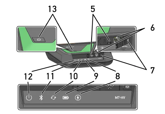
| Name | |
| 5 | USB-C interface |
| 6 | Ethernet interface |
| 7 | Power supply socket Connect a power adapter to the power supply socket to supply the MT-HV with voltage and to charge the internal battery. |
|
8 | High-voltage This LED indicates if e.g. a high-voltage measurement process is active or if high voltage is applied to the test prods (e.g. in case of insulation resistance measurement). The different status indications are explained in the section User Communication |
|
9 | Battery status display This LED indicates the various battery charging states. The different battery status display are explained in the section User Communication |
| 10 | Update This LED indicates that an update is in progress. |
| 11 | Bluetooth® This LED indicates that the MT-HV is connected via Bluetooth®. |
|
12 | MT-HV status This LED indicates e.g. if the MT-HV is active or ready for operation. The different status indications are explained in the section User Communication |
| 13 | ON/OFF button Switch the MT-HV on and off with the ON/OFF button. |
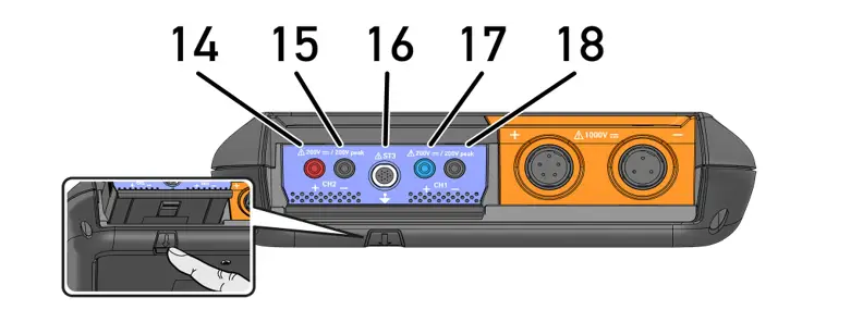
| Name | |
|
14 / 15 | Ports Scope 2 (CH2) Connect the test leads to Scope 2 (CH2) here. • red = signal + • black = signal – |
| 16 | ST3 connector Connect the blue and the green clamp meter here. |
|
17 / 18 | Ports Scope 1 (CH1) Connect the test leads to Scope 1 (CH1) here. • blue = signal + • black = signal – |
Device Description High-
Voltage Test Leads
High-Voltage Test Leads
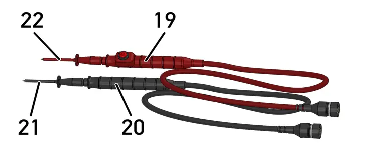
| Name | |
| 19 | High-voltage test lead (red) • 4-mm-test connection (safety connector) for manufacturer-specific test adapters • incl. function button to start or to confirm measurements |
| 20 | High-voltage test lead (black) 4-mm-test connection (safety connector) for manufacturer-specific test adapters |
| 21 | Attachable test prod (black) |
| 22 | Attachable test prod (red) |
User Communication
Meaning of the LEDs with different interactions
| Interaction | LED |
| When the MT-HV is switched off and you briefly push ON/OFF, the yellow LED will light up until the start procedure is completed. | |
| • After the start procedure is completed, the LED is permanently green and the MT-HV is ready for operation. • When the MT-HV is switched on and you briefly push ON/OFF, the green LED will flash several times until the MT-HV is shut down entirely. | |
| If the connection is inactive or if there is no connection in battery mode, the MT- HV will switch off after 2 minutes. Before that the red LED will light red for 60 seconds. | |
| If an update is in progress, the LED will flash several times green until the update is finished. | |
| The green LED is permanently on if the high-voltage measurement is active. | |
| The yellow LED is permanently on if high voltage is switched to the test prods. | |
| The blue LED is permanently on if the MT-HV has Bluetooth® connection. | |
| Explanation of the battery status display:
more than 40 % of entire charge • The battery status indicator flashes green if the battery is being charged. • The status indicator is permanently green if the battery is fully charged.
20 % to 40 % of entire charge
20 % or less (charging required!) • The battery status indicator flashes red if battery charge is less than 10 %. |
|
Putting Into Operation
This section describes how to connect the MT-HV with the mega macs X.
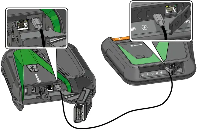
Connecting the MT-HV with the mega macs X
Initial setup:
Proceed as follows to connect the MT-HV with the mega macs X for the first time:
- Connect the MT-HV with the supplied USB-C cable to the mega macs X.The mega macs X is recognizing the MT-HV automatically and is starting the pairing process.

- Remove the USB-C
Now the MT-HV is connected with the mega macs X.NOTICE Continuous operation:
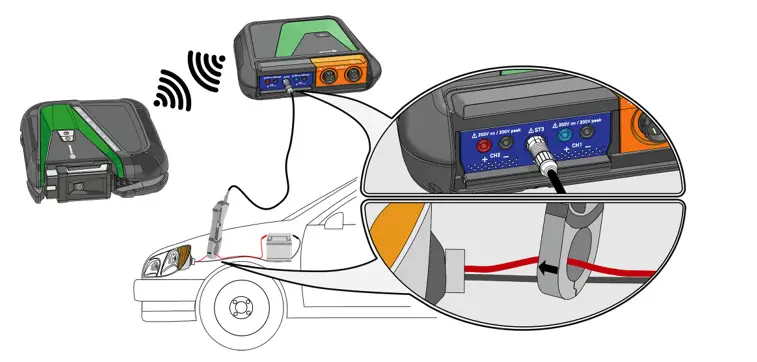
• The MT-HV is connected via Bluetooth® with the mega macs X.
• There is a Wi-Fi connection between the displaying device (tablet etc.) and the mega macs X.
Low-Voltage Measurement
| NOTICE You can alternatively use the measurement module MT 56 for measuring voltage, current and resistance. |
This section describes how to perform a low-voltage measurement in connection with the MT 77 measurement
module. The following pictures illustrate the exact proceeding.
Inserting the MT 77 into the MT-HV
Proceed as follows to insert the MT 77 into the MT-HV:
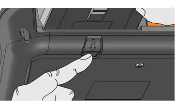
- Press the unlocking button of the MT-HV.
The module releases from the module slot.
- Insert the MT 77 into the free module slot, pay attention that it locks into place
- Draw the module out of the module
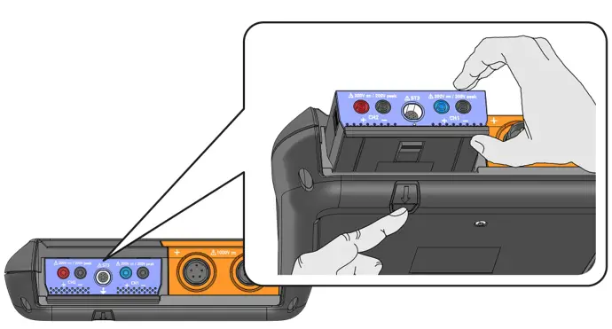
Now the MT 77 is instered in the module slot of the MT-HV.
Connecting the Test Lead to the MT 77
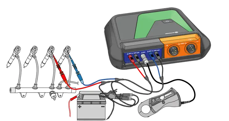
Connecting the Current Clamp to Vehicle and MT 77
High-Voltage Measurement
This section describes how to perform a high-voltage measurement. The following pictures illustrate the exact proceeding.
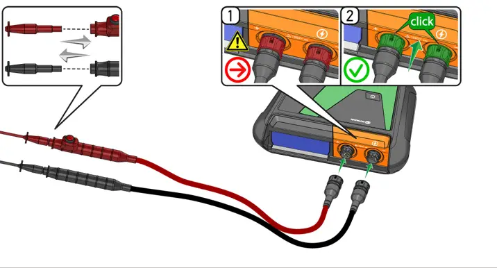
Connecting High-Voltage Test Leads to the MT-HV
| Danger Danger to life due to electric voltage It is a precondition for performing high-voltage measurements that the user has knowledge of automotive technology and is therefore aware of the sources of danger and risks in the workshop and on motor vehicles. An additional country-specific qualification is mandatory. |
| | CAUTION Danger of destruction of the MT-HV and/or the automotive electronics • Only used certified test prods and high-voltage test leads. • Check the test prods and the high-voltage test leads for damage prior to every application (visual inspection). |
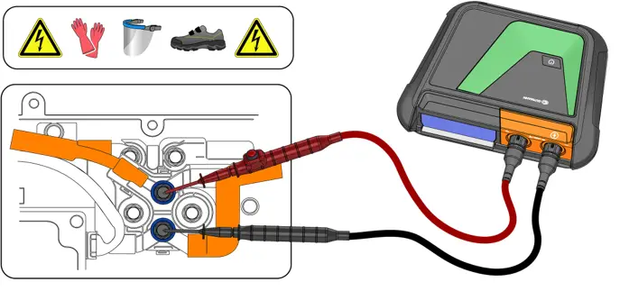
Performing High-Voltage Measurements
|
| DANGER Danger to life due to electric voltage on vehicles with high-voltage systems • It is a precondition for performing high-voltage measurements that the user has knowledge of automotive technology and is therefore aware of the sources of danger and risks in the workshop and on motor vehicles. An additional country-specific qualification is mandatory. • Ensure, that the component to be evaluated is de-energized. • Pay attention not to touch connections and connecting cables of the high-voltage battery module. • Pay attention not to touch energized components. |
| NOTICE The following image is an example. |
General information
Care and Maintenance
- Do not use cleaning agents.
- Only use a dry cloth.
- Replace damaged cables/accessories immediately.
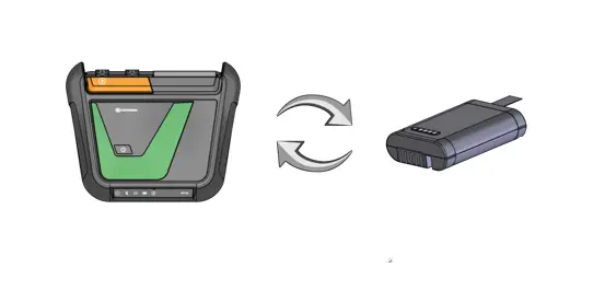
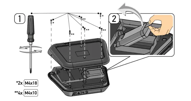
- Only use original spare parts. You can order these parts via the Order Center of the Hella Gutmann GmbH. Note: The battery is available separately. Unscrew and remove the back cover of the housing to be able to exchange the battery:
DANGER
Danger to life due to electric voltage on vehicles with high-voltage systems.
Ensure that the test prods and the high-voltage test leads are not connected to any component during that.
CAUTION
Danger of destruction of the MT-HV and/or the automotive electronics Disconnect the MT-HV from the voltage supply during that.
Disposal
| NOTICE The guidelines listed here are exclusively valid within the European Union. |
In compliance with Directive 2012/19/EU of the European Parliament and Council of 4 July 2012 relating to Waste Electrical and Electronic Equipment (WEEE), and the German national statute governing the distribution, return and environmental disposal of electrical and electronic equipment (Electrical and Electronic Equipment Act – ElektroG) of 20 October 2015 in its current version, we are obliged to take back this device, distributed by us after 13 August 2005, at the end of its service life free of charge and to dispose of it in accordance with the above-mentioned directives.
Since, in the case of the present tool, this relates to exclusively commercially used equipment (B2B), it must not be handed over to a public disposal facility.
The device can be disposed of at the following address (specifying the date of purchase and the device numbers): Hella Gutmann Solutions GmbH
Am Krebsbach 2
79241 Ihringen
GERMANY
WEEE reg. no.: DE 25419042
Phone: +49 7668 9900-0
Fax: +49 7668 9900-3999
E-mail: info@hella-gutmann.com
Technical data of the MT-HV
| Supply voltage | 12 to 32 V |
| Power input | max. 10 W |
| Current draw | max. 1 A |
| Ambient temperature | Recommended: 10 to 35 °C Working range: 0 to 45 °C Storage temperature: -10 to 60 °C |
| Suitable for humid environment? | No |
| Use at high altitude | max. 2000 m above NHN (normal height null) |
| Relative air humidity | approx. 10 to 90 % (not condensating) |
| Continuous operation | Yes |
| Weight | approx. 1.7 kg |
| Dimensions | 300 x 360 x 80 mm (L x W x H) |
| IP degree of protection | IP20 |
| Overload protection | max. 1 kV |
| Measuring channels | 1 (galvanically isolated) |
|
Measured variables of the HV modules | • High-voltage measurement up to 1 kV • Potential equalization measurement • Insulation resistance measurement • Resistance measurement (service disconnect plug) |
| Interfaces | • USB-C • Bluetooth® • RJ45 |
| Ranges | |
| Voltage | • Measuring range: ± 1000 V DC • Resolution: 0.1 V • Precision: ± (1 % of reading + 2 digits) |
|
Insulation resistance measurement | • Measuring range: 10k to 10GΩ • Test voltage: variably adjustable to 1000 V DC in steps of 10 V • Resolution: 0.1 • Precision: ± (3 % of reading + 3 digits) |
|
Resistance (service disconnect plug) | • Measuring range: 0 to 10 Ω • Resolution: 0.01 Ω • Measuring current: 200 mA • Precision: ± (2.5 % of reading + 4 digits) |
|
Potential equalization measurement | • Measuring range: 0 to 10 Ω • Resolution: 0.01 Ω • Measuring current: 200 mA • Precision: ± (2.5 % of reading + 4 digits) |
| High-Voltage Test Leads | |
|
Red | • Length: 1500 mm • Handpiece with function button • With 4 mm test connection for manufacturer-specific test adapters • incl. plug-on measuring probe |
|
black | • Length: 1500 mm • Handpiece • With 4 mm test connection for manufacturer-specific test adapters • incl. plug-on measuring probe |
Technical Data of the MT 77
| Supply voltage | 5 V (through module interface) |
| Power input | 10 W |
| Current draw | max. 2 A |
| Ambient temperature | Recommended: 10 to 35 °C Working range: 0 to 45 °C Storage temperature: -10 to 60 °C |
| Suitable for humid environment? | No |
| Use at high altitude | max. 2000 m above NHN (normal height null) |
| Relative air humidity | approx. 10 to 90 % |
| Continuous operation | Yes |
| Weight | approx. 270 g |
| Dimensions | 43 x 110 x 136 mm (H x W x D) |
| IP degree of protection | IP20 |
| Bandwidth | max. 10 MHz |
| Sampling rate | 64 MSa/s |
| Memory depth | 64 kB |
| Amplitude resolution | 14 bit |
| Overload protection | max. 200 V |
| Measuring channels | 2 (galvanically isolated) |
|
Measured variables | • Voltage • Current (external clamp meter) • Resistance • Pressure (external LPD kit) |
| Measuring accuracy | +/- 2.5 % |
|
Interfaces | • 4x safety socket 4 mm (2 per measuring channel) • 1x ST3 (12-pin) • 1x module interface (USB) ST3 connections • 6x communication • 1x voltage inlet 10-15 V • 1x voltage outlet +17 V • 2x scope (+/-) • 1x hardware detection (coding) • 1x ground |
| Range | |
|
Voltage | • Range 10 positions, 0.01 to 20 V/Div • Measurable voltage max. 200 V |
|
Current |
|
| Resistance |
|
| Pressure (with LPD kit) |
|


