![]()
TECHNOLOGY WSME200 Digital IGBT Inverter AC-DC TIG-MMA-Pulse
User Manual
PLEASE READ FIRST
Thank you for purchasing our equipment!
For your safety, please read this user’s manual before installation and operation.
Thanks for your support!
INTRODUCTION
WSME series welder is developed with advanced inverter technology, with digital control through microprocessor, it transfers 50/60HZ industrial frequency power to 30KHZ high-frequency power through the inverter part combined with IGBT and so on. Then voltage reducing- rectifying-wave filtering, as well as pulse-width modulation (PWM) and closed-loop back circuit control technology to output stable DC current for welding. Thus this unit has the following characteristics: high efficiency, energy-saving, portability, good dynamic characteristics, stable arc, continuous adjustable current, and so on. Also, it’s with protection function against overvoltage, overcurrent, and overheating to ensure the safety and durability of the welder. Especially the twice-inverter technology and the pure square wave output feature the excellent welding characteristics of good arc stiffness, concentrated heat, strong reverse clearing ability, and wide clear range, and the arc is not easy to break with low current.
WSME series welder is AC/DC welder with wide application, which can realize MMA welding, DC CC TIG welding, DC PULSE TIG welding, AC CC TIG welding, AC PULSE TIG welding, applied to various materials welding inlcuding carbon steel, copper, titanium, aluminum, aluminum-magnesium alloy, etc.
Thanks for purchasing our product and giving us more valuable advice. And we will commit to perfect products and services to create the top brand in the welding industry.
 Earth leakage protection device should be installed when you use the machine.
- Within an indoor environment, the machine may produce radio waves, so the user should make full of preventive measures.
- Please make sure the power supply is off before any connecting operation.
- If the distance between the workpiece and machine is too far (50m), and welding cables are too long, please select the cable with a bigger section to reduce the voltage dropping.
SECURITY CAUTION
![]() Please make good protection as there will be the possibility of harm during the arc welding process. For more details please refer to the Operator Safety Guide, which complies with the preventive requirements of the manufacturer.
Please make good protection as there will be the possibility of harm during the arc welding process. For more details please refer to the Operator Safety Guide, which complies with the preventive requirements of the manufacturer.
Electric shock—–may be fatal![]() Install the earth cable according to the standard. No touching electric parts with bare or wet hands or wet clothes. Make sure that the working piece and you are in insulation circumstances. Make sure that your work is in a safe condition.
Install the earth cable according to the standard. No touching electric parts with bare or wet hands or wet clothes. Make sure that the working piece and you are in insulation circumstances. Make sure that your work is in a safe condition.
Smoke—–may be harmful![]() Keep your head out of the smoke Make sure the air is flowing to avoid breathing the smoke during the welding process.
Keep your head out of the smoke Make sure the air is flowing to avoid breathing the smoke during the welding process.
Arc radiation—–may be harmful to your eyes and skin![]() Wear a suitable welding mask and clothes to protect your eyes and skin. Use a suitable screen or curtain to keep the onlookers away from the emission
Wear a suitable welding mask and clothes to protect your eyes and skin. Use a suitable screen or curtain to keep the onlookers away from the emission
Fire![]() Welding sparks may cause fire, make sure that welder is close to non-flammable material
Welding sparks may cause fire, make sure that welder is close to non-flammable material
Noise—-Excessive noise may be harmful to your hearing![]() Please wear something to protect your ears from the noises Warn the onlooker’s latent harm may be caused by the noise
Please wear something to protect your ears from the noises Warn the onlooker’s latent harm may be caused by the noise
Break-down: ask the professional for help
Any problems in setting up or operating please turn to this manual first. If you still can not understand after reading this manual, please contact your supplier or manufacturer to get professional assistance.
MAIN PARAMETER
Model→ | WSME200 | WSME315 | WSME350 | WSME500 | ||||
| Input power voltage(V) | AC220V±15% | AC380V±15% | AC380V±15% | AC380V±15% | ||||
| Input voltage frequency (HZ) | 50/60 | 50/60 | 50/60 | 50/60 | ||||
| Rated input power capacity (KVA) | TIG | MMA | TIG | MMA | TIG | MMA | TIG | MMA |
| 4.6 | 7 | 9 | 13 | 10.6 | 15.1 | 19 | 25.3 | |
| Rated input current (A) | 20.7 | 32.2 | 13.7 | 19.7 | 16.1 | 22.9 | 28.9 | 38.4 |
| Output current range (A) | 5-200 | 40-200 | 5-315 | 40-315 | 5-350 | 40-350 | 5-500 | 40-500 |
| No-load voltage (V) | 59 | 67 | 77 | 77 | ||||
| Duty cycle (%) | 60 | 60 | 60 | 60 | ||||
| No-load consumption(W) | 60 | 60 | 60 | 60 | ||||
| Efficiency(%) | 85 | 85 | 85 | 85 | ||||
| Power factor | 0.93 | 0.93 | 0.93 | 0.93 | ||||
| Insulation class | F | F | F | F | ||||
| Protection class | IP21S | IP21S | IP21S | IP21S | ||||
| Weight (KG) | 20 | 26 | 39 | 47 | ||||
| Dimension (mm) | 480*201*295 | 500*280*435 | 622×280×480 | 622×280×480 | ||||
PANEL DESCRIPTION
Front panel: 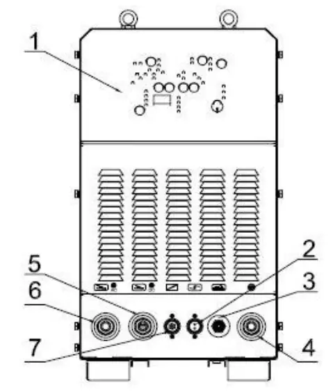
Rear panel: 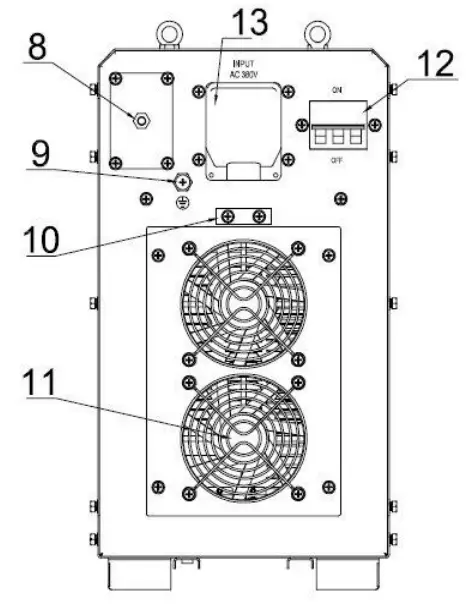
| No. | Name | No. | Name |
| 1 | Control Panel | 8 | Gas Interface |
| 2 | Torch Connector | 9 | Ground Screw |
| 3 | Gas-electric Integration | 10 | Power cable fixing groove |
| 4 | Torch Switch Connector | 11 | Fan |
| 5 | DC positive output terminal | 12 | ON/OFF Switch |
| 6 | AC positive output terminal | 13 | Power cable box |
| 7 | Remote Control |
Pls, note: AC and DC 2 in 1 for WSME200/315, WSME200 is without a remote control connector.
PANEL DETAILS
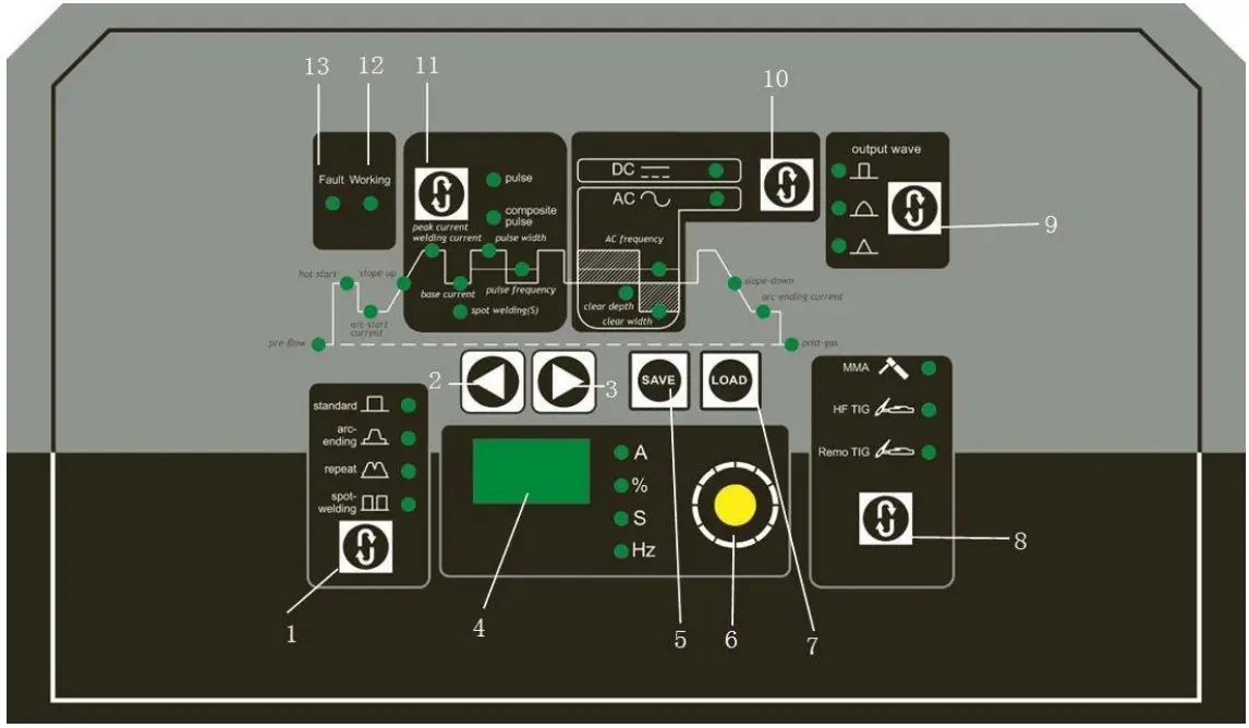
- Control panel
Control panel according to the below drawing for the function selection and parameter setting.
The Control panel includes a digital display, adjustable knob, selection knob, and indicator led.
- Panel description
No. Name Description 1 Welding function selection used for welding mode selection under different functions, the standard model is the “no arc ending” function, the gradient is “with arc ending”
2 Parameter selection Shift the indicator light leftwards 3 Parameter selection Shift the indicator light rightwards 4 Display To display the value of each parameter 5 Save key Used for saving set welding data, 10sets of different welding data are available 6 Parameter adjustment knob To adjust the value of the set parameter 7 Load key To load the different welding parameter which has been saved 8 Welding mode selection Press 3S under TIG situation then can switch to MMA by releasing 9 Waveform selection key Three different welding output waveforms can be selected, such as square wave, sine wave, and triangular wave
10 AC DC selection Function selection for AC DC 11 Pulse selection Selection for pulse and composite pulse, composite pulse only can be used under AC status 12 High voltage indicator No-load voltage output indicator 13 Warning indicator Warning indicator for overheat, overcurrent
Parameter setting(Eg.WSME315)
| Short name | Full name | Description | Adjust range | Default value |
| Pre-gas | Gas feeding in advance | Gas feeding time before welding | 0~10 S | 0.1 S |
| Hot start | Arc striking current | The current during arc striking | 10~315A | 100A |
| Arc start | Arc starting current | With the arc-ending mode to adjust the preset current value of arc striking | 5~315A | 40 A |
| Slope-up | Slope-up time | With the arc-ending mode to adjust the current slope-up time from the arc striking to welding | 0~10 S | 5 S |
| Spot time | Spot time | The welding time in the spot welding status | 0~10 S | 3 S |
| Base value | Base current | With the pulse method to adjust the low current | 5~315A | 10 A |
| Welding | Welding current | Adjusting the welding current or pulse peak current | 5~315A | 150 A |
| % | pulse width | With the pulse method to adjust the ratio between peak current and pulse cycle | 10~90 % | 50 % |
| Pulse frequency | Pulse frequency | With the pulse method to adjust the pulse frequency value | 0.1~20HZ | 5HZ |
| Clear width | Clear width | Adjust the clear width when welding with the AC method | 10~90 % | 30 % |
| Clear depth | Clear depth | Adjust the clear depth when welding with the AC method | -50~+50 % | 0% |
| AC frequency | AC frequency | Adjust the exchange current frequency when welding with the AC method | 20~200HZ | 80HZ |
| Slope- down | Slope-down time | With the arc-ending mode to adjust the current slope-down time from welding to arc-ending | 0~10 S | 5 S |
| Arc ending | Arc ending current | With the arc-ending mode to adjust the preset current value of arc ending | 5~315A | 20 A |
| Post-gas | Post gas time | Post gas time after welding | 0~10 S | 5 S |
INSTALLMENT
The welding machine is equipped with a power voltage compensation device. When power voltage fluctuates within ±10% of rated voltage, it can still work normally. In order to reduce the voltage drop when using long cables, cable of the bigger section is suggested. If the cable is too long, it may affect the performance of the power system as well as other properties, so we suggest you use the recommended length.
- Be sure the vents are not blocked, lest the cooling system will not work.
- Use inducting cable with the section not less than 6 mm² to connect the housing to the ground. The way is from the ground-connecting screw at the rear to the earth device.
- Connect the power cable to the power supply box which is equipped with an earth leakage protection device. Make sure the input power is of the proper voltage and meanwhile please ensure the voltage fluctuation is within the applicable range.
- In actual use, maybe the power cable and welding cable length are not enough, please refer to the below form to choose a suitable cable.
List 1
The section and the length of the welding cable
| Rated current I/A | Section (mm2) | ||||||||
| L=20m | L=30m | L=40m | L=50m | L=60m | L=70m | L=80m | L=90m | L=100m | |
| 100 | 25 | 25 | 25 | 25 | 25 | 25 | 25 | 28 | 35 |
| 150 | 35 | 35 | 35 | 35 | 50 | 50 | 60 | 70 | 70 |
| 200 | 35 | 35 | 35 | 50 | 60 | 70 | 70 | 70 | 70 |
| 300 | 35 | 50 | 60 | 60 | 70 | 70 | 70 | 85 | 85 |
| 400 | 35 | 50 | 60 | 70 | 85 | 85 | 85 | 95 | 95 |
| 500 | 50 | 60 | 70 | 85 | 95 | 95 | 95 | 120 | 120 |
| 600 | 60 | 70 | 85 | 85 | 95 | 95 | 95 | 120 | 120 |
List 2
The rated current and the diameter of the output cable (Max. temperature of conductor 60℃)
| Rated section of the copper conductor (mm2) | Rated current of the max duty cycle (A) | ||||
| 100% | 85% | 60% | 30% | 20% | |
| 16 | 105 | 115 | 135 | 190 | 235 |
| 25 | 135 | 145 | 175 | 245 | 300 |
| 35 | 170 | 185 | 220 | 310 | 380 |
| 50 | 220 | 240 | 285 | 400 | 490 |
| 70 | 270 | 195 | 350 | 495 | 600 |
| 95 | 330 | 360 | 425 | 600 | 740 |
| 120 | 380 | 410 | 490 | 690 | 850 |
| 185 | 500 | 540 | 650 | 910 | 1120 |
Warnings:
- Please don’t connect or disconnect the cables during working, it will terribly damage the machine.
- When the machine is powered by the generator, please don’t connect the powerful sensitive load to the generator(such as the power motor, air compressor, and so on), otherwise, the big power machine will damage the cutting machine.
INSTALLMENT & OPERATION
MMA
- Open the cable connecting box at the rear of the machine and connect the power cable to the terminal screw then fasten it. After that please unscrew the screw of the cable fixing groove, remove the groove cover, fix the cable into the groove then install the cover and fasten the screw.
- Put the cable connector of the electrode holder to the negative terminal “-“ of the front panel, and fasten it clockwise.
- Please connect the earth clamp to the positive terminal “+”, and fasten it clockwise.
- Please pay attention to the connecting polarity and there are two connecting methods for DC welding machines: positive connection and negative connection.
4.1 Positive connection: holder connects with “-“polarity, work-piece with the “+” polarity.
4.2 Negative connection: work-piece to the “-“polarity, electrode holder to the “+” polarity.
4.3 Choose a suitable method according to the welding requirement. If the unsuitable method is selected, it will cause an unstable arc, more spatters, and sticking. If so, please change the polarity of the welding cables. Normally choose a positive connection. - Switch to “MMA”.
- Switch on the power switch, meanwhile, the digital display will be on, then the cooling fan will start working immediately.
- Please select the appropriate welding current and rod according to the thickness of the workpiece.
(Taking notice of distinction for the positive connection terminal between AC and DC welding)
Electrode standard
| Electrode Diameter (mm) | 1.6 | 2.0 | 2.5 | 3.2 | 4.0 | 5.0 | 6.0 |
| Welding Current (A) | 25-40 | 40-65 | 50-80 | 100-130 | 160-210 | 200-270 | 260-500 |
MMA installation instruction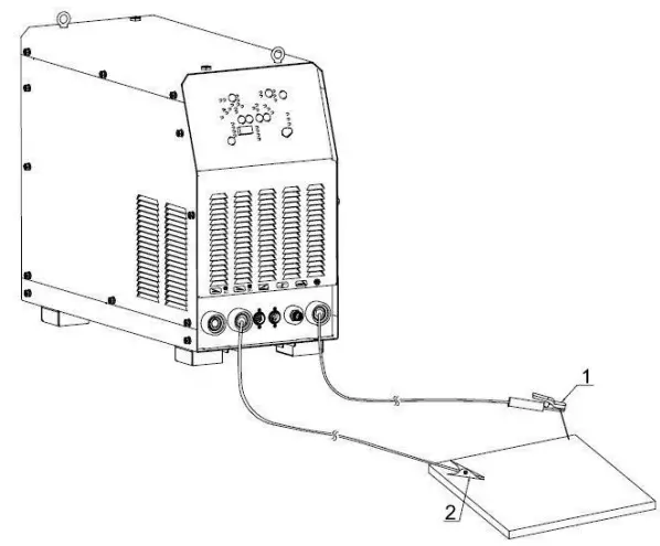
| No. | Name |
| 1 | Electrode holder |
| 2 | Earth clamp |
TIG
- Connect gas cylinder with copper connection on the rear panel of the machine then fasten the connector with a hose clamp to prevent from gas leaking, the gas access includes cylinder, argon gas regulator, and gas hose.
- Correctly install the TIG torch according to the sketch diagram, connect the gas-electricity integration connector of another head of the torch, air socket to the torch connector, and torch switch of the panel, and then fasten it clockwise.
- Please connect the plug of the earth clamp to the positive terminal “+”, fasten it clockwise, and use the earth clamp to hold the workpiece.
(Taking notice of distinction for the positive connection terminal between AC and DC welding)
Remote control (Foot Pedal) function
The setting current of the machine is the max. current of foot pedal when you connect remote foo pedal. For example, if the current of the machine is 200A, the adjustment current range of the foot pedal is 5-200A under the switch on when you press the torch after the machine working.
TIG installation instruction
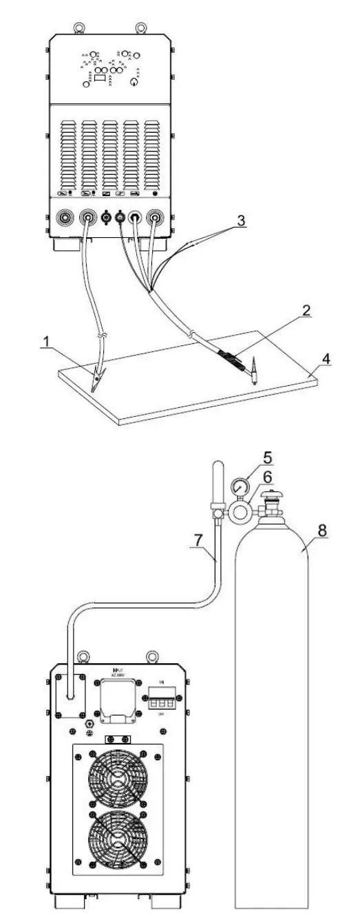
| No. | Name |
| 1 | Earth clamp |
| 2 | TIG torch |
| 3 | The water inlet/outlet torch connector |
| 4 | Workpiece |
| 5 | Pressure meter |
| 6 | Gas regulator |
| 7 | Gas hose |
| 8 | Gas cylinder |
(1) Tig welding operation
- DC TIG welding operation
a. Please make sure the connection is correct with each part, then power on the machine, the panel indicator will come on, and the fan will start work.
b. Press the button ⑧ “gas check” on the panel to release the air valve, adjust the gas follow to the specified value according to the craft standard, then once again press the button to shut the gas valve.
c. Select the welding method according to welding process requirement, press button ⑩ to select AC/DC, press button ⑪ to select pulse or no pulse, and press button ① to select “standard” or “arc-ending”.
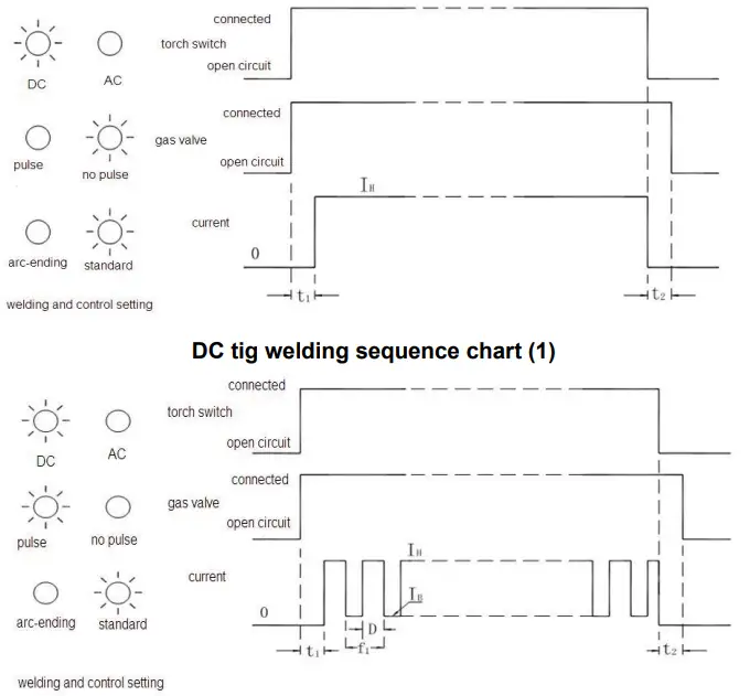
d. DC TIG welding sequence chart as below: DC tig welding sequence chart (2)
- AC TIG welding operation:
a. Ensure the correct connection of each part, then shut the power switch, the panel indicator is on, and the fan is working.
b. Press the button gas check ⑧ to release the gas valve, adjust gas flow to the argon regulator, then press the button and close the gas valve.
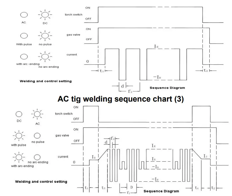
c. Select the welding mode according to the technique requirement, press button ⑩to select“AC/DC”.press button ⑪to select pulse/no pulse, press button ①to select control mode with/without arc-ending.
d. AC TIG welding Sequence Diagram(Refer to below):
 AC tig welding sequence chart (4)
 IH-welding current t₁- pre-flow time D- pulse width IB-base current t₂- post-gas time d-clear width IQ-arc start current t₃-slope-uptime f₁-pulse frequency IS-arc-ending current t₄-slope-down time f₂-AC frequency - clear width:
It’s necessary to do arc clearance when you use AC TIG aluminum welding, you have to adjust the strength according to the clear width. The setting of clear width and welding effect, also, electrode consumption is as follows:Meter(%) 10 33(standard) 50 Electrode consumption Less Normal More Molten depth Deep Normal Shallow Clear width Narrow Normal Wide - AC waveform:
Setting Result Soft Square wave Easier to control the puddle Sine wave Soft sounding arc Triangular wave Reducing heat input on the thinner materials also provides better cleaning in the anodic oxidation application.
 DC tig welding sequence chart (2)
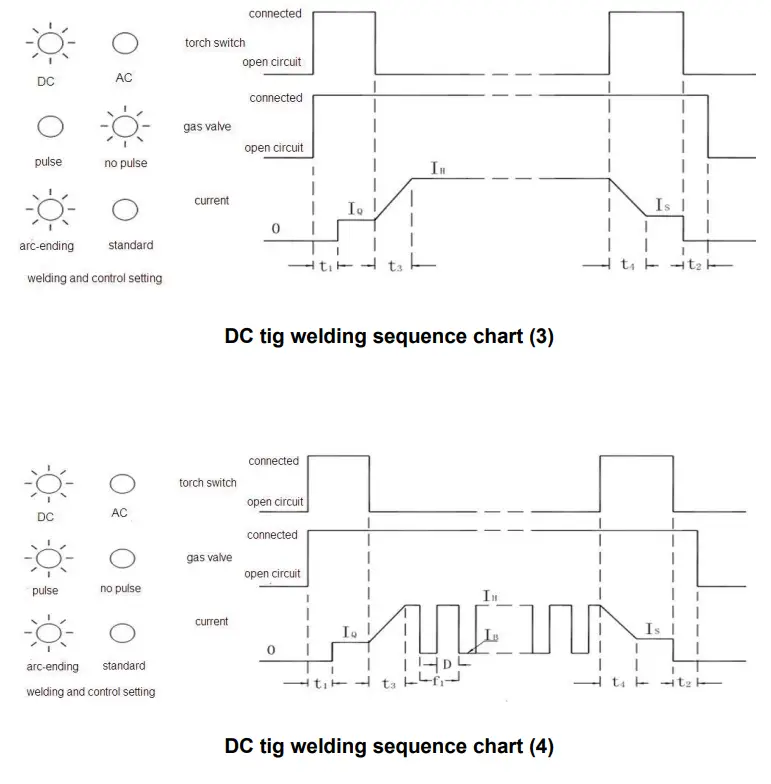

 AC tig welding sequence chart (4)
 ATTENTION
- Environment
1.1 The machine can perform in an environment with dry air with a dampness proportion of max 90%.
1.2 Ambient temperature should be between -10ºC to 40ºC.
1.3 Avoid welding in sunshine or drippings.
1.4 Please do not use the machine in the air which is polluted with conductive dust or corrosive gas. - Safety points
The welding machine has adopted a protection circuit to avoid broken under over voltage, over current, and overheating. When the voltage, output current, and temperature of the machine exceed the standard level, the unit will stop working automatically. In order to avoid damage to the unit, the operator must pay attention to the following:
2.1 Please make sure the working area is adequately ventilated!
The machine adopts air cooling, so be sure the intake is not in a block or covered. It should be more than 0.3 meters from the welding machine to the surroundings. And good ventilation is important for better performance and the longevity of the unit.
2.2 No overload!
Please avoid working overload as it will shorten the machine’s life. Normally it’s overloaded if the current display shows abnormal code during welding, namely, its overrated duty cycle. So please stop welding immediately and resume working after the display is on normally. (Rated duty cycle 60% means: take 10 mins as a circle, the machine works for 6mins and stops for 4mins under the rated output current).
2.3 No overvoltage
An automatic compensation circuit of voltage will assure that the welding current is kept in the allowable arrangement. If the power voltage exceeds the limitation, it will damage the welder. In that case, please take relevant preventive measures.
2.4 Assure the ground screw is well connected
There is a ground screw with the symbol at the rear panel of the unit. Choose a section of inducting cable over 6mm 2 and reliably grounding to prevent static electricity and leaking.
TROUBLESHOOTING
Below failures are related to fittings, welding materials, environment factor, and supply power, please try to improve the welding environment.
- Welding spot become black
It means the welding spot is oxygenated without good protection, and please check the followings:
1.1 Make sure the argon cylinder is open and has enough pressure which should be above 0.5 MPa.
1.2 Make sure the pressure valve is open and has enough flow. In order to save gas, you can choose different flows according to the different welding currents, but it may result in the protective gas can’t cover the welding spot entirely. Argon flow should be not less than 3L/min.
1.3 The simple method to check whether the argon flows out or not is to feel the gas through a nozzle with your finger.
1.4 Gas flow is not well sealed or argon is not pure.
1.5 If the airflow is too strong, it may low down the welding quality. - Arc-striking is difficult and easily pauses
2.1 Make sure the rod or tungsten is of good quality otherwise it is difficult to meet the request of the high-quality welding.
2.2 It will be hard to strike an arc if the rod is not dry enough or the tungsten is not sharpened. It will also cause unstable arc and the welding quality will be influenced by
increased defect. - Output current not up to the rated value
Current will not match the setting value when power voltage departs from the rated value. While voltage is lower than the rated value, the max output may be lower than the rated value. - Current is unstable during the welding process and it may be caused by the followings:
4.1 Electric network voltage changes.
4.2 Harmful interferences from the electric network or other equipment.
4.3 Undersize the external input cable. - Too much spatter under MMA welding
5.1 High current with a rod of small diameter.
5.2 The output terminal polarity is reversed. For normal use, you can adopt a positive connection which means the holder connects to the “-” polarity and the work-piece to the “+” polarity, so please exchange.
REPAIR AND MAINTENANCE
Repair and maintenance should be done by a professional person and please make sure the power supply is cut off before any operation. When you meet any insoluble problem please get in touch with us.
Repair and maintenance
- Check the internal and external circuits of the welding machine regularly and make sure the connections are correct and tight.
- Avoid water or steam infiltrating the internal machine. If it occurs please dry the machine then check carefully before welding.
- If the welder will not be used for a long time, please pack it and store it in the dry air.
- Blowing away the dust with dry clean pressed air regularly, if the welder is used under conditions of dense smoke or polluted air, please clean the machine every day.
Attention: The highest voltage of the machine is above 1000V, please don’t open the machine optionally, electric shock proof should be done during the repair.
Common fault and elimination method
| Fault | Solution measures |
| Nothing happened after turning on the machine | 1. Check if the power supply is normal 2. Check if the power switch is broken down 3. Check the auxiliary power circuit 4. Check if the connecting wire is loose |
| No output current with high-frequency discharge | 1. Check if the connecting wire of the torch and earth clamp open circuit 2. Check if the earth clamp is connecting with the workpiece well |
| With output current, but unadjustable | 1. Check and adjust the potentiometer 2. Check the control module |
| The abnormal indicator is on | 1. Environment temperature too high or cooling system has a problem 2. Long time welding 3. Torch switch is broken 4. Inside control circuit is broken |
| the oxide film is unopened during aluminum welding | 1. Check if choose AC 2. Increase duty ratio or clear workpiece’s oxide film 3. Check the middle board |
USER’S RECORD
| Purchase Date: |
| Serial No. (Rear Panel of the Machine): |
| Dealer’s Name: |
| Dealer’s Address: |
| Dealer’s Tel / Fax: |
| Notes: |
Please attach the proof of purchase
![]() YJG-ESED-E000001
YJG-ESED-E000001


