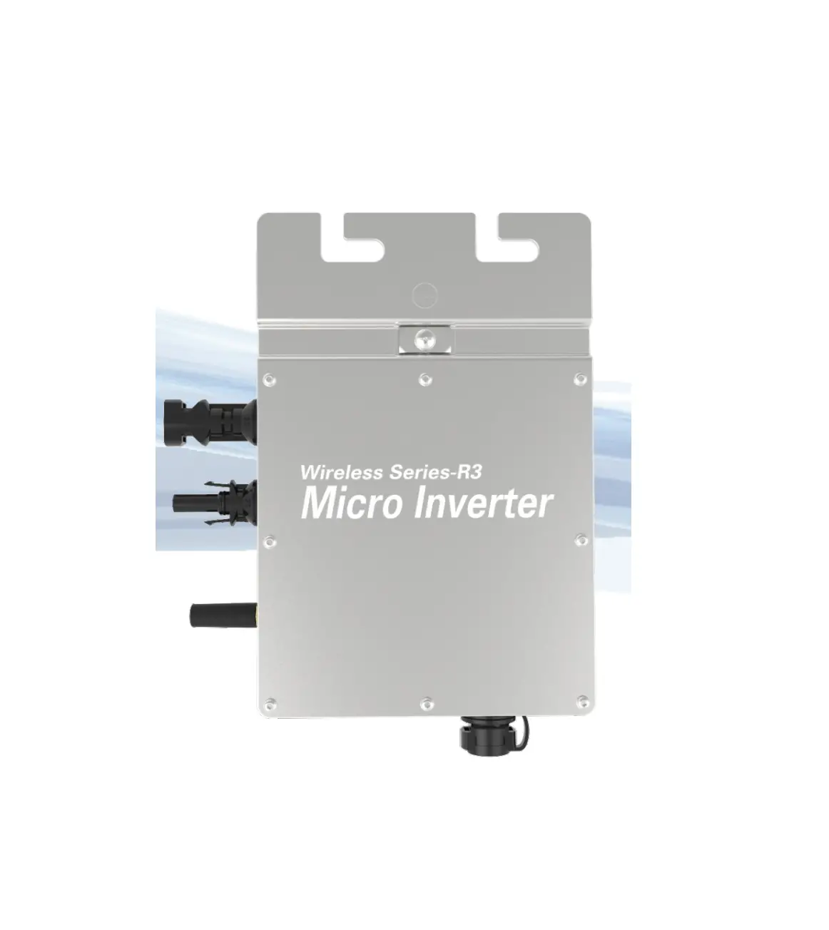
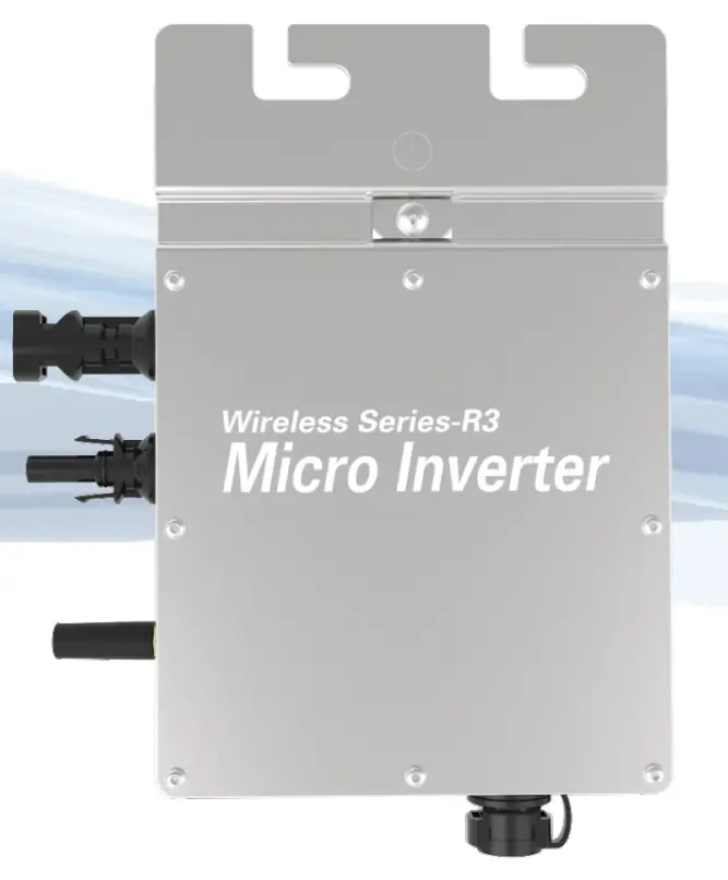
Dongguan Kaideng Energy Technology Co Ltd WVC-295 Micro Inverter
 Green Energy
Smart InverterExpert
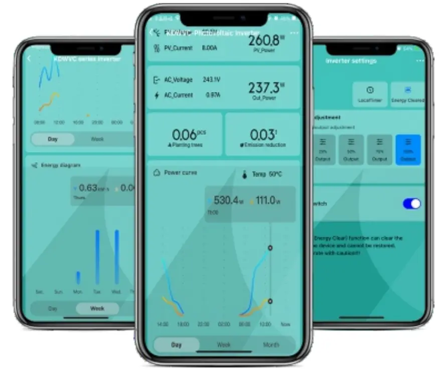
IoT Monitoring Platform
Smart mobile “core” life
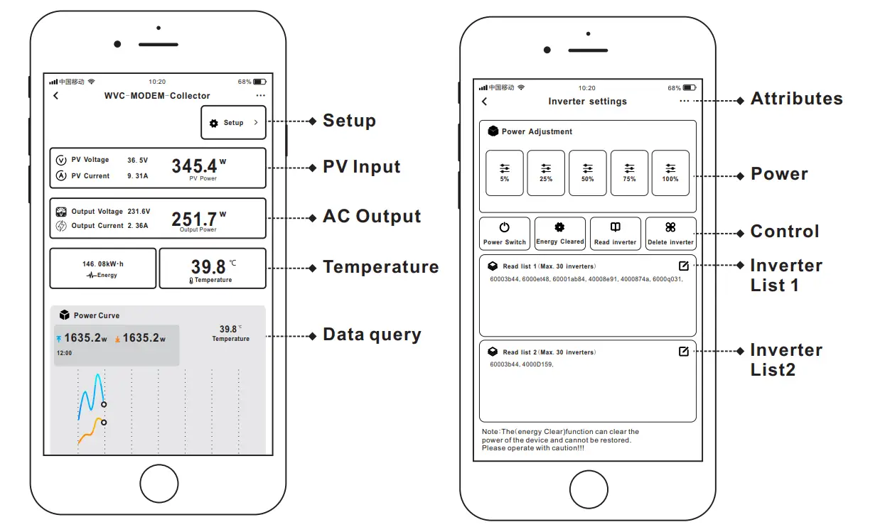
- CO-2 induced environmental analysis
- Daily and total energy generation in kWh
- Actual DC input voltage, current and power
- Actual AC output voltage, current and power
- Inverter temperature
- Historical (daily, weekly, monthly) power curve
- Power losses due to weather induced effects
- Optional limitation of power output
- Online switch for the inverter start stop
 | |
 |  |
![]() CO-2 induced environmental analysis
CO-2 induced environmental analysis![]() Daily and total energy generation in kWh
Daily and total energy generation in kWh![]() Actual DC input voltage, current and power
Actual DC input voltage, current and power![]() Actual AC output voltage, current and power
Actual AC output voltage, current and power![]() Inverter temperature
Inverter temperature![]() Optional limitation of power output
Optional limitation of power output![]() Online switch for the inverter start stop
Online switch for the inverter start stop![]() Historical (daily, weekly, monthly) power curve
Historical (daily, weekly, monthly) power curve
| model | WVC-295 | |
| Recommend use panels | 1*300Watt | |
| Output voltage mode | 120/230V Auto switch | |
| PV Open circuit voltage | 30-60VDC | |
| Operating voltage range | 22-60V | |
| Starting voltage range | 22-60V | |
| short-circuit current | 14.5A | |
| Maximum working current | 12.8A | |
| Output parameters | @120V | @230V |
| Output peak power | 300Watt | 300Watt |
| Rated output power | 295Watt | 295Watt |
| Output current | 2.45A | 1.28A |
| AC voltage range | 80-160VAC | 180-280VAC |
| AC frequency range | 48-51Hz/58-61Hz | 48-51Hz/58-61Hz |
| Power factor | >95% | >95% |
| Number of branch connections. | 15PCS(Single) | 30PCS(Single) |
| Output efficiency | @120V | @230V |
| Static MPPT efficiency | 99.5% | 99.5% |
| Max output efficiency | 95% | 95% |
| Loss of power at night | <0.5W | <0.5W |
| Total current harmonics | <5% | <5% |
| Appearance and technical features | |
| Temperature range | -40°C to +65°C |
| Size(L×W×H) | 213mm×167mm×32mm |
| Net amount | 0.82kg |
| Waterproof grade | Ip67 |
| Heat dissipation mode | Self-cooling |
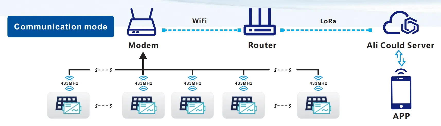
| Communication mode | 433MHz |
| Power transmission mode | Reverse transmission,Load priority |
| monitoring system | APP |
| Electromagnetic Detection | EN61000-6-1:2007 EN6100-6-3:2007+A1:2011+AC:2012 |
| Power Grid standard | EN50549-1、EN 50549-2、NBR 16149:2013、UL1741 |
| Power grid detection | IEC/EN 62109-1、 IEC/EN 62109-2、 IEC 62116、IEEE 1547 |
| Certificate | CE,Patented technology |
| Packing weight | ||
| Specifications | Each(Packing) | Box(16PCS) |
| weight | 1KG | 15.5KG |
| Size | 245×202×60mm | 430×400×270mm |
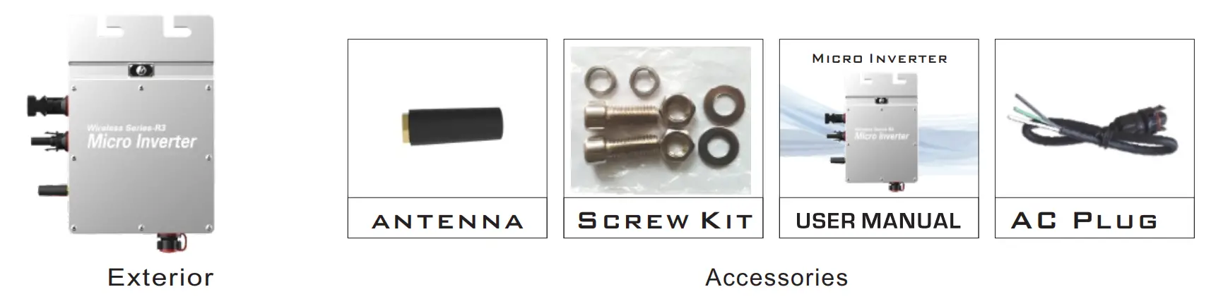
Detailed
System diagram
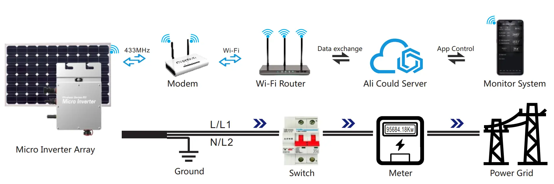
Note: You can purchase a professionally customized AC bus with a T-type connector.
Use this AC bus as the AC bus for each branch. Connect it hand in hand to form a modular micro-inverter branch wiring system.
LED indicator function of micro inverter
- Red light keeps on ——————————–The equipment enters the preparatory working state;
- Red light flashes ———————————- The device enters the delayed start-up state;
- Blue light flashes quickly ————————MPPT maximum power point search status;
- Blue light keeps on——————————–MPPT maximum power point locked state;
- Blue light turns to red light for a long time—-a) Island protection; b)Frequency protection; c) Fault; d) Software shutdown;
e) AC voltage over-voltage protection;
f) DC voltage over-voltage protection;
Normal working indicator flashing process
Connect the micro-inverter correctly to the AC and DC terminals and then power on:
The red light keeps on for 3 seconds → the red light flashes for 30 seconds → the blue light flashes quickly (MPPT maximum power point search) → the blue light keeps on, (MPPT lock).
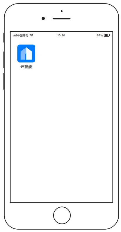 | DOWNLOAD Cloud Intelligence APPPlease use the QR code to scan and install the “Cloud Intelligence” client application,System version: Android 5.0, IOS 9 and above |
| |
 | |
 note
note
 note
notea) Connect the two communication antennas on the collector (Modem) as required;
b) Place the collector in an appropriate location to ensure that the wifi signal source can be received normally and Form a good communication distance with the inverter;
c) The connected Wi-Fi network needs to be in 2.4G communication mode;
d) Please reset the collector for the first use;
 Reset
Reset
 Reset
ResetPress and hold the reset button for more than 5 seconds, and Reday will go out and light up again after 5 seconds.
Release the button at this time, and the device will complete the reset.
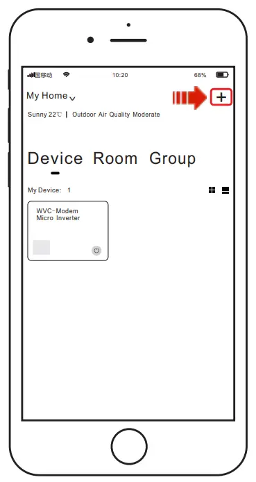
- Add device
Open the intelligent monitoring software “Cloud Intelligence” APP to log in Account, click the “+” icon in the upper right corner to start adding.
*If a device has been created under the current account,(You can click on the device icon below to enter the details page for query or operation)
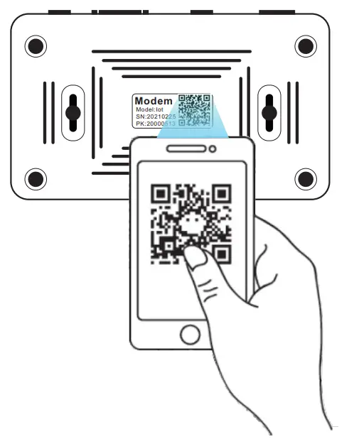
- Entry equipment
When the smart APP changes to the QR code scanning state, scan the QR code label at the bottom of the Modem. At this time, the APP will automatically collect the body code of the Modem,and automatically jump to the Wi-Fi connection page, and enter the current Wi-Fi Click Next after the password;
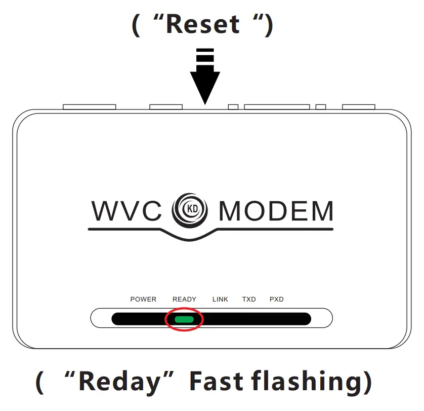
- Distribution network
Connect the Modem to the power supply as required, and quickly press the “Reset” button.
When the “Reday” indicator turns from a long on state to a fast flashing state, the Modem will enter the network distribution state;
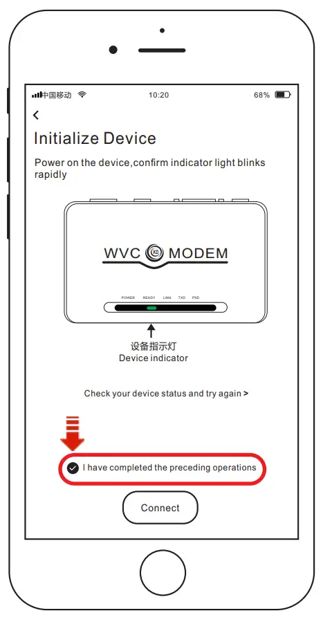
- Initialization
After completing the network configuration of the modem, return to the phone initialization device operation page,check the “I have completed the above operations” below and click the “start connection” button, then the page will jump to the signal search page and the Link on the modem The indicator light will become a fast flashing state.
When a WiFi signal is found,the indicator light will flash slowly until the network configuration is completed, and the indicator light will return to a steady state.The page jumps to the completion page, please click “Finish”
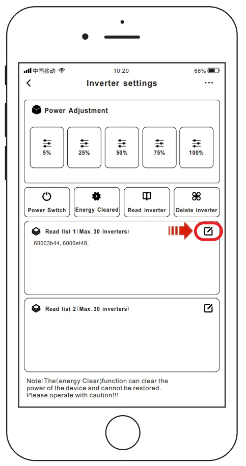
- Add inverter
When the initialization is completed, please click the “Settings” menu in the upper right corner, find the inverter list item on the setting page, click the “Edit” button, and fill in the 8-digit code on the inverter to complete the inverter Add to.
Remarks- When multiple inverters need to be added, theIn the English state, “,” comma separated and ended. Such as: 60001234, 6000E312,
- Each Modem can monitor 60 inverters at the same time;3. A total of 2 lists, each list can be filled with 30 inverter codes;

Features
Smart APP can realize real-time data transmission with the cooperation of Alibaba Cloud IoT Through graphs and graphic displays in time, users can understand the operation of the power station. The user can monitor the operation and adjust the output power function of the system.
Cloud Intelligence APP
INTELLIGENT Iot MONITORING MODEM Number of data collectors per Modem Built-in WiFi IoT data terminal Can be used on any smart device (Android/iOS)
| |
| |
- CO-2 induced environmental analysis
- Daily and total energy generation in kWh
- Actual DC input voltage, current and power
- Actual AC output voltage, current and power
- Inverter temperature
- Historical (daily, weekly, monthly) power curve
- Power losses due to weather induced effects
- Optional limitation of power output
- Online switch for the inverter start stop


